1996 CHRYSLER VOYAGER bulb
[x] Cancel search: bulbPage 556 of 1938

COMPASS MINI-TRIP COMPUTER (CMTC)
MODULE
REMOVAL
(1) Disconnect battery negative cable.
(2) Remove overhead console.
(3) Remove the six screws holding CMTC module
to overhead console (Fig. 6).
(4) Remove CMTC module from console.
INSTALLATION
For installation, reverse the above procedures.
COMPASS MINI-TRIP COMPUTER (CMTC) LAMP
BULBS
REMOVAL
(1) Remove overhead console.
(2) Rotate bulb socket counterclockwise one quar-
ter turn (Fig. 7).(3) Pull bulb socket from CMTC module.
INSTALLATION
For installation, reverse the above procedures.
FRONT HEADER READING/COURTESY LAMP
REMOVAL
(1) Place a small flat tool in the slot at the forward
edge of the lamp lens and twist (Fig. 8).
(2) Remove lens.
(3) Insert the tip of the tool under the inside, rear
edge of the reflector/light shield. Carefully pry reflec-
tor/light shield out.
(4) Remove the lamp by pressing forward the brass
terminal and rotating the lamp clockwise to remove.
INSTALLATION
For installation, reverse the above procedures.
When installing the lamp lens, first guide the switch
contact tab on the lens between the lamp switch
plunger and the lamp bezel. Then snap lens onto the
two lens pivots on the bezel.
OVERHEAD CONSOLE
REMOVAL
(1) Open the transmitter bin door (Fig. 9).
(2) Remove screw holding the overhead console to
the headliner. With the screw removed the console is
retained by one engagement tab located inside the
eyeglass storage bin.
(3) Open the eyeglass bin door.
(4) Press the retaining tab which is located
directly above the door latch.
(5) Lower rear of console away from headliner.
(6) Pull console rearward to disengage clips hold-
ing front of console to roof armature and lower con-
sole.
(7) Disconnect wire connectors from back of CMTC
and reading lamps. Ensure the connectors lock tabs
are fully depressed before disconnecting.
(8) Remove overhead console.
INSTALLATION
For installation, reverse the above procedures.
READING/COURTESY LAMP
Removal
(1) Using a trim stick, lightly pry outward the for-
ward end of reading lamp lens (Fig. 10).
(2) Rotate reading/courtesy lamp socket one quar-
ter turn counterclockwise.
(3) Pull socket out of lamp (Fig. 11).
(4) Pull lamp from socket.
Fig. 6 Compass Mini-Trip Computer
Fig. 7 CMTC Lamp Bulbs
8V - 6 OVERHEAD CONSOLENS
REMOVAL AND INSTALLATION (Continued)
Page 1340 of 1938
Shutdown (ASD) RelayÐPCM Output in this section
for relay operation.
TORQUE CONVERTER CLUTCH SOLENOIDÐPCM
OUTPUT
Three-speed automatic transaxles use a torque con-
verter clutch solenoid. The PCM controls the engage-
ment of the torque converter clutch through the
solenoid. The torque converter clutch is engaged only
in direct drive mode. Refer to Group 21 for transaxle
information.
MALFUNCTION INDICATOR (CHECK ENGINE)
LAMPÐPCM OUTPUT
The PCM supplies the malfunction indicator (check
engine) lamp on/off signal to the instrument panel
through the CCD Bus. The CCD Bus is a communi-
cations port. Various modules use the CCD Bus to
exchange information.
The Check Engine lamp comes on each time the
ignition key is turned ON and stays on for 3 seconds
as a bulb test.
The Malfunction Indicator Lamp (MIL) stays on
continuously, when the PCM has entered a Limp-In
mode or identified a failed emission component. Dur-
ing Limp-in Mode, the PCM attempts to keep the
system operational. The MIL signals the need for
immediate service. In limp-in mode, the PCM com-
pensates for the failure of certain components that
send incorrect signals. The PCM substitutes for the
incorrect signals with inputs from other sensors.
If the PCM detects active engine misfire severe
enough to cause catalyst damage, it flashes the MIL.
At the same time the PCM also sets a Diagnostic
Trouble Code (DTC).
For signals that can trigger the MIL (Check
Engine Lamp) refer to Group 25, On-Board
Dianostics.
SOLID STATE FAN RELAYÐPCM OUTPUT
The radiator fan runs at a variable speed depend-
ing on coolant temperature and A/C system pressure.
The radiator fan circuit contains a Solid State Fan
Relay (SSFR). Refer to the Group 8W for a circuit
schematic.
A 5 volt signal is supplied to the SSFR. The PCM
provides a pulsed ground for the SSFR. Depending
upon the amount of pulse on time, the SSFR puts out
a proportional voltage to the fan motor at the lower
speed. For instance, if the on time is 30 percent, then
the voltage to the fan motor will be 3.6 volts.
When engine coolant reaches approximately 102ÉC
(215ÉF) the PCM grounds the SSFR relay. If engine
coolant reaches 207ÉC (225ÉF) the PCM grounds the
high speed ground relay and high speed fan relay. If
the fan operates at high speed, the PCM de-energizes
the high speed relay and high speed ground relay
when coolant temperature drops to approximately
101ÉC (214ÉF). When coolant temperature drops to
101ÉC (214ÉF) the fan operates at low speed. The
PCM de-energizes the low speed relay when coolant
temperature drops to approximately 93ÉC (199ÉF).
Also, when the air conditioning pressure switch
closes, the fan operates at high speed. The air condi-
tioning switch closes at 285 psi610 psi. When air
conditioning pressure drops approximately 40 psi, the
pressure switch opens and the fan operates at low
speed.
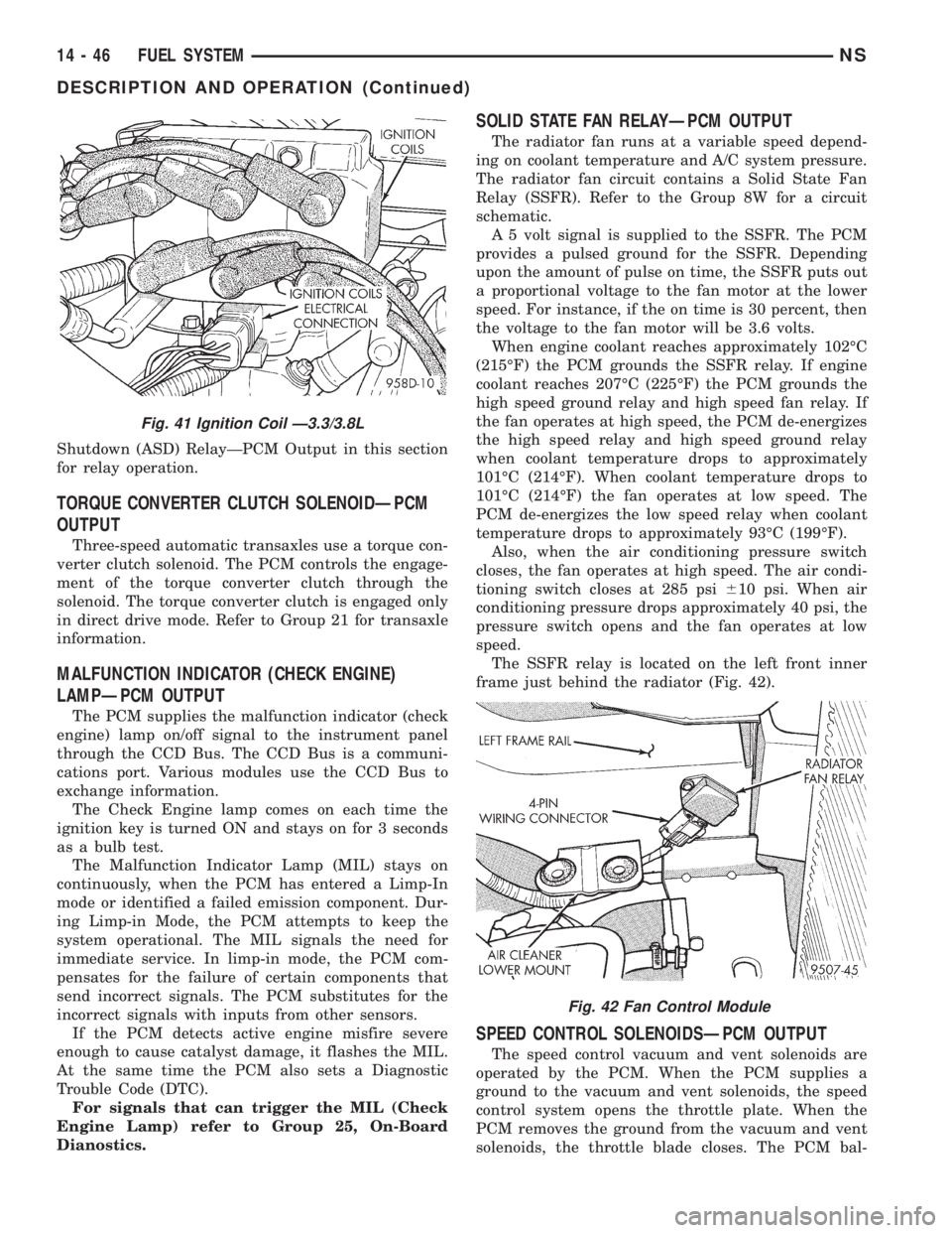
The SSFR relay is located on the left front inner
frame just behind the radiator (Fig. 42).
SPEED CONTROL SOLENOIDSÐPCM OUTPUT
The speed control vacuum and vent solenoids are
operated by the PCM. When the PCM supplies a
ground to the vacuum and vent solenoids, the speed
control system opens the throttle plate. When the
PCM removes the ground from the vacuum and vent
solenoids, the throttle blade closes. The PCM bal-
Fig. 41 Ignition Coil Ð3.3/3.8L
Fig. 42 Fan Control Module
14 - 46 FUEL SYSTEMNS
DESCRIPTION AND OPERATION (Continued)
Page 1384 of 1938
REMOVAL AND INSTALLATION
ACCELERATOR PEDAL
CAUTION: Be careful not to damage or kink the
cable core wire (within the cable sheathing) while
servicing the accelerator pedal or throttle cable.
REMOVAL
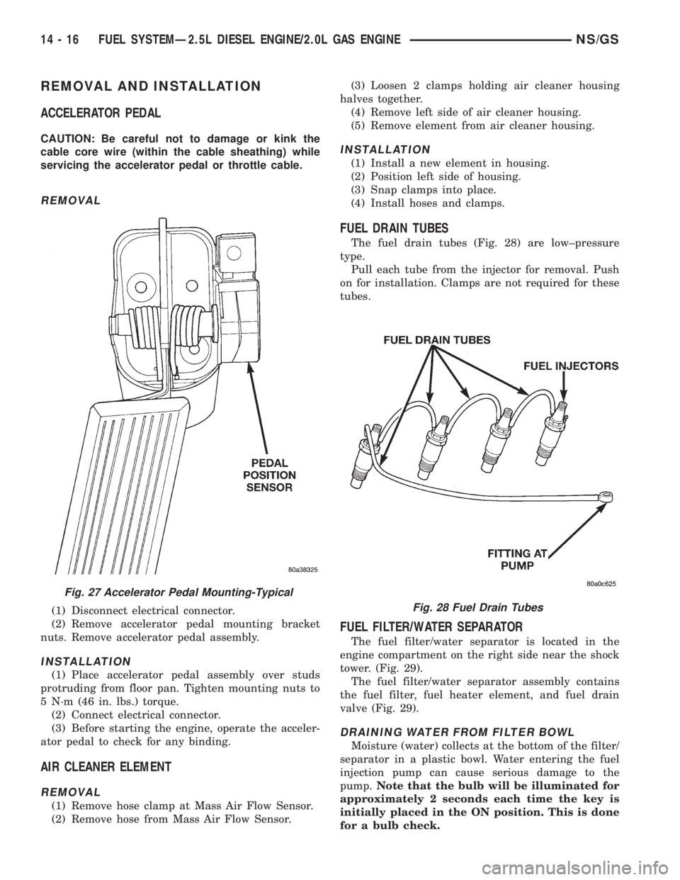
(1) Disconnect electrical connector.
(2) Remove accelerator pedal mounting bracket
nuts. Remove accelerator pedal assembly.
INSTALLATION
(1) Place accelerator pedal assembly over studs
protruding from floor pan. Tighten mounting nuts to
5 N´m (46 in. lbs.) torque.
(2) Connect electrical connector.
(3) Before starting the engine, operate the acceler-
ator pedal to check for any binding.
AIR CLEANER ELEMENT
REMOVAL
(1) Remove hose clamp at Mass Air Flow Sensor.
(2) Remove hose from Mass Air Flow Sensor.(3) Loosen 2 clamps holding air cleaner housing
halves together.
(4) Remove left side of air cleaner housing.
(5) Remove element from air cleaner housing.
INSTALLATION
(1) Install a new element in housing.
(2) Position left side of housing.
(3) Snap clamps into place.
(4) Install hoses and clamps.
FUEL DRAIN TUBES
The fuel drain tubes (Fig. 28) are low±pressure
type.
Pull each tube from the injector for removal. Push
on for installation. Clamps are not required for these
tubes.
FUEL FILTER/WATER SEPARATOR
The fuel filter/water separator is located in the
engine compartment on the right side near the shock
tower. (Fig. 29).
The fuel filter/water separator assembly contains
the fuel filter, fuel heater element, and fuel drain
valve (Fig. 29).
DRAINING WATER FROM FILTER BOWL
Moisture (water) collects at the bottom of the filter/
separator in a plastic bowl. Water entering the fuel
injection pump can cause serious damage to the
pump.Note that the bulb will be illuminated for
approximately 2 seconds each time the key is
initially placed in the ON position. This is done
for a bulb check.
Fig. 27 Accelerator Pedal Mounting-Typical
Fig. 28 Fuel Drain Tubes
14 - 16 FUEL SYSTEMÐ2.5L DIESEL ENGINE/2.0L GAS ENGINENS/GS
Page 1416 of 1938
The speed sensor generates 8 pulses per sensor
revolution. These signals, in conjunction with a
closed throttle signal from the throttle position sen-
sor, indicate a closed throttle deceleration to the
PCM. When the vehicle is stopped at idle, a closed
throttle signal is received by the PCM (but a speed
sensor signal is not received).
In addition to determining distance and vehicle
speed, the output from the sensor is used to control
speed control operation.
SPEED CONTROLÐPCM INPUTS
The speed control system provides five separate
inputs to the PCM; On/Off, Set, Resume/Accel, Cancel,
and Decel.. The On/Off input informs the PCM that
the speed control system has been activated. The Set
input informs the PCM that a fixed vehicle speed has
been selected. The Resume input indicates to the PCM
that the previous fixed speed is requested.
Speed control operation will start at 50 km/h±142
km/h (35±85 mph). The upper range of operation is
not restricted by vehicle speed. Inputs that affect
speed control operation are vehicle speed sensor and
throttle position sensor.
Refer to Group 8H for further speed control infor-
mation.
DIESEL PCM RELAYÐPCM INPUT
A 12 volt signal at this input indicates to the PCM
that the Diesel relay has been activated. The Diesel
relay is located in the PDC. The PDC is located next
to the battery in the engine compartment. For the
location of the relay within the PDC, refer to label on
PDC cover.
This input is used only to sense that the Diesel
relay is energized. If the PCM does not see 12 volts +
at this input when the Diesel relay should be acti-
vated, it will set a Diagnostic Trouble Code (DTC).
FIVE VOLT POWERÐPCM OUTPUT
This circuit supplies approximately 5 volts to
power the Accelerator Pedal Postion Sensor, Mass Air
Flow Sensor, and A/C Pressure Sensor.
ENGINE COOLANT GAUGEÐPCM OUTPUT
Refer to the Instrument Panel and Gauges group
for additional information.
ENGINE OIL PRESSURE GAUGEÐPCM OUTPUT
Refer to the Instrument Panel and Gauges group
for additional information.
GLOW PLUG LAMPÐPCM OUTPUT
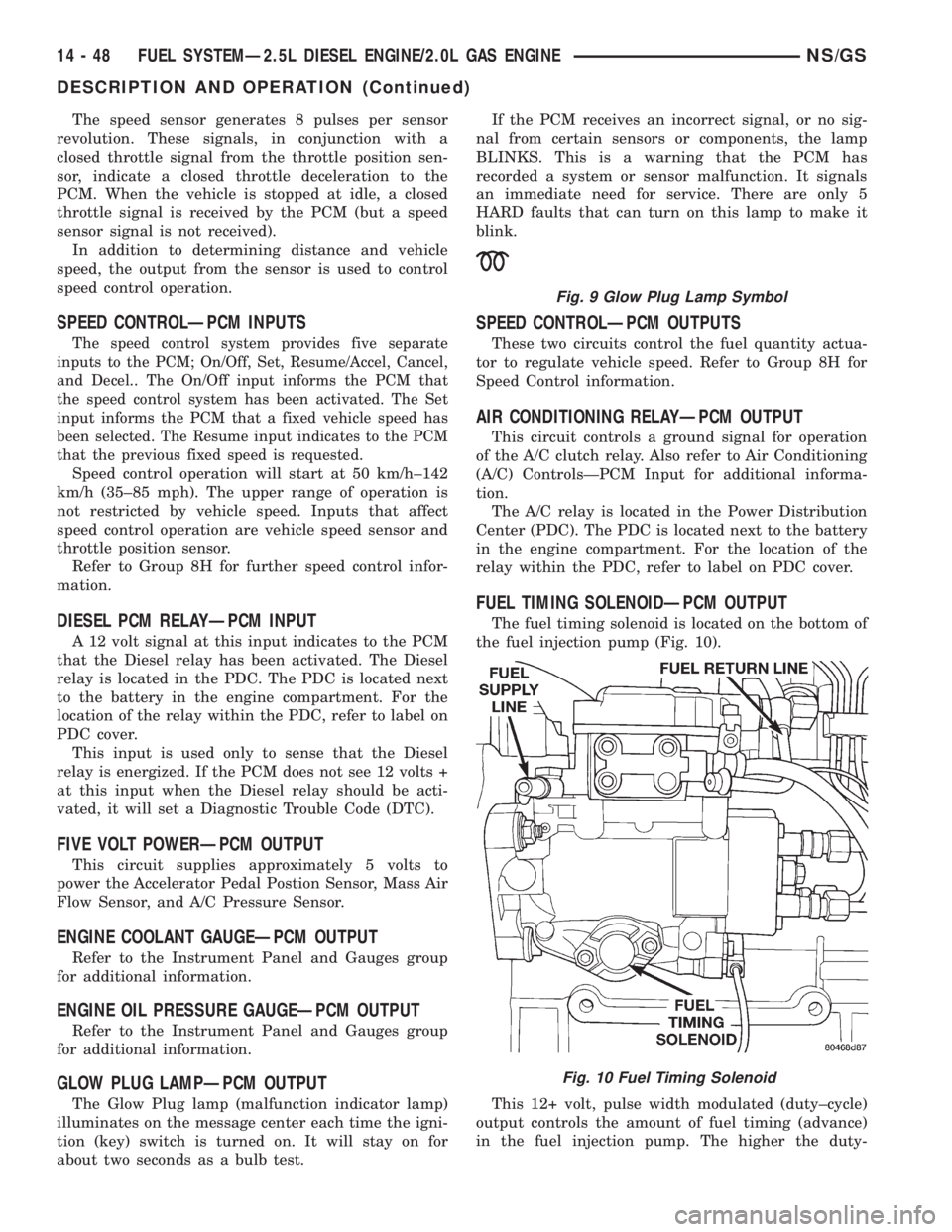
The Glow Plug lamp (malfunction indicator lamp)
illuminates on the message center each time the igni-
tion (key) switch is turned on. It will stay on for
about two seconds as a bulb test.If the PCM receives an incorrect signal, or no sig-
nal from certain sensors or components, the lamp
BLINKS. This is a warning that the PCM has
recorded a system or sensor malfunction. It signals
an immediate need for service. There are only 5
HARD faults that can turn on this lamp to make it
blink.
SPEED CONTROLÐPCM OUTPUTS
These two circuits control the fuel quantity actua-
tor to regulate vehicle speed. Refer to Group 8H for
Speed Control information.
AIR CONDITIONING RELAYÐPCM OUTPUT
This circuit controls a ground signal for operation
of the A/C clutch relay. Also refer to Air Conditioning
(A/C) ControlsÐPCM Input for additional informa-
tion.
The A/C relay is located in the Power Distribution
Center (PDC). The PDC is located next to the battery
in the engine compartment. For the location of the
relay within the PDC, refer to label on PDC cover.
FUEL TIMING SOLENOIDÐPCM OUTPUT
The fuel timing solenoid is located on the bottom of
the fuel injection pump (Fig. 10).
This 12+ volt, pulse width modulated (duty±cycle)
output controls the amount of fuel timing (advance)
in the fuel injection pump. The higher the duty-
Fig. 9 Glow Plug Lamp Symbol
Fig. 10 Fuel Timing Solenoid
14 - 48 FUEL SYSTEMÐ2.5L DIESEL ENGINE/2.0L GAS ENGINENS/GS
DESCRIPTION AND OPERATION (Continued)
Page 1857 of 1938
REAR HEATING AND AIR CONDITIONING SYSTEM
INDEX
page page
GENERAL INFORMATION
INTRODUCTION......................... 41
DESCRIPTION AND OPERATION
REAR BLOWER RESISTOR BLOCK.......... 41
REAR HEATER AND A/C LINES............. 41
SYSTEM OPERATION.................... 41
DIAGNOSIS AND TESTING
DIAGNOSTIC PROCEDURES............... 43
REMOVAL AND INSTALLATION
AIR DISTRIBUTION DUCT-A/C.............. 43
AIR DISTRIBUTION DUCT-HEATER.......... 43
EVAPORATOR AND EXPANSION VALVE...... 44MODE DOOR ACTUATOR................. 49
MODE DOOR........................... 49
REAR AIR CONDITIONING LINES........... 45
REAR HEATER A/C AIR OUTLETS........... 45
REAR HEATER A/C BLOWER MOTOR........ 46
REAR HEATER A/C UNIT.................. 46
REAR HEATER CORE.................... 48
REAR HEATER LINES.................... 49
REAR HEATER-A/C AUXILIARY CONDENSER . . 45
REAR HEATER-A/C CONTROL ILLUMINATION
BULB............................... 46
GENERAL INFORMATION
INTRODUCTION
For proper operation of the rear heating A/C sys-
tem, refer to Owner's Manual supplied with the vehi-
cle.
DESCRIPTION AND OPERATION
REAR BLOWER RESISTOR BLOCK
The rear blower motor resistor is not serviceable
separately. The resistor is integral to the blower
motor. If resistor is faulty, it is necessary to replace
the complete blower motor.
REAR HEATER AND A/C LINES
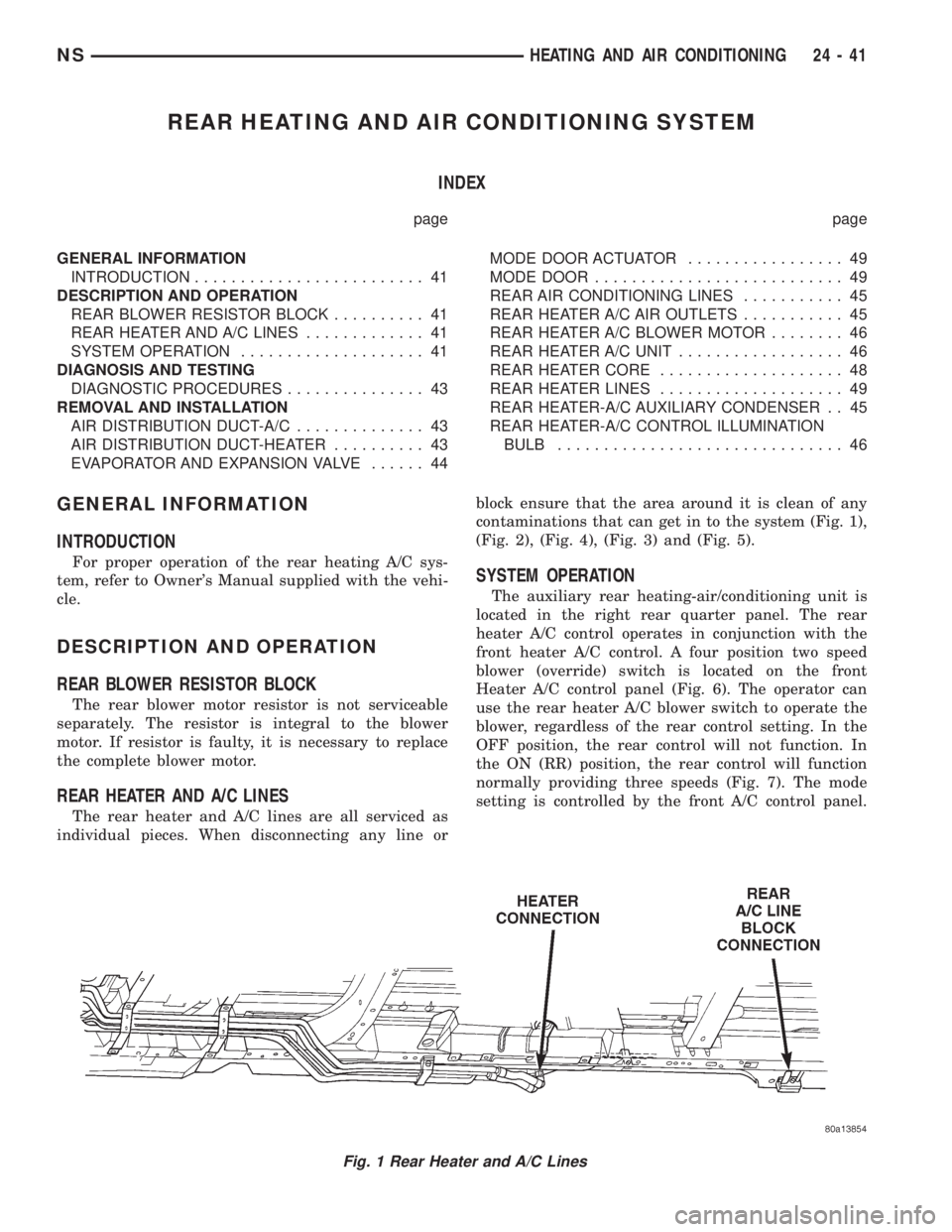
The rear heater and A/C lines are all serviced as
individual pieces. When disconnecting any line orblock ensure that the area around it is clean of any
contaminations that can get in to the system (Fig. 1),
(Fig. 2), (Fig. 4), (Fig. 3) and (Fig. 5).
SYSTEM OPERATION
The auxiliary rear heating-air/conditioning unit is
located in the right rear quarter panel. The rear
heater A/C control operates in conjunction with the
front heater A/C control. A four position two speed
blower (override) switch is located on the front
Heater A/C control panel (Fig. 6). The operator can
use the rear heater A/C blower switch to operate the
blower, regardless of the rear control setting. In the
OFF position, the rear control will not function. In
the ON (RR) position, the rear control will function
normally providing three speeds (Fig. 7). The mode
setting is controlled by the front A/C control panel.
Fig. 1 Rear Heater and A/C Lines
NSHEATING AND AIR CONDITIONING 24 - 41
Page 1862 of 1938
REAR HEATER A/C BLOWER MOTOR
REMOVAL
(1) Remove the right quarter trim panel and D-pil-
lar trim. Refer to Group 23, Body for service proce-
dures.
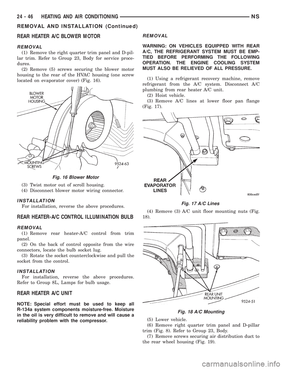
(2) Remove (5) screws securing the blower motor
housing to the rear of the HVAC housing (one screw
located on evaporator cover) (Fig. 16).
(3) Twist motor out of scroll housing.
(4) Disconnect blower motor wiring connector.
INSTALLATION
For installation, reverse the above procedures.
REAR HEATER-A/C CONTROL ILLUMINATION BULB
REMOVAL
(1) Remove rear heater-A/C control from trim
panel.
(2) On the back of control opposite from the wire
connectors, locate the bulb socket lug.
(3) Rotate the socket counterclockwise and pull the
socket from the control.
INSTALLATION
For installation, reverse the above procedures.
Refer to Group 8L, Lamps for bulb usage.
REAR HEATER A/C UNIT
NOTE: Special effort must be used to keep all
R-134a system components moisture-free. Moisture
in the oil is very difficult to remove and will cause a
reliability problem with the compressor.
REMOVAL
WARNING: ON VEHICLES EQUIPPED WITH REAR
A/C, THE REFRIGERANT SYSTEM MUST BE EMP-
TIED BEFORE PERFORMING THE FOLLOWING
OPERATION. THE ENGINE COOLING SYSTEM
MUST ALSO BE RELIEVED OF ALL PRESSURE.
(1) Using a refrigerant recovery machine, remove
refrigerant from the A/C system. Disconnect A/C
plumbing from rear heater A/C unit.
(2) Hoist vehicle.
(3) Remove A/C lines at lower floor pan flange
(Fig. 17).
(4) Remove (3) A/C unit floor mounting nuts (Fig.
18).
(5) Lower vehicle.
(6) Remove right quarter trim panel and D-pillar
trim (Fig. 8). Refer to Group 23, Body.
(7) Remove screws securing air distribution duct to
the rear wheel housing (Fig. 19).
Fig. 16 Blower Motor
Fig. 17 A/C Lines
Fig. 18 A/C Mounting
24 - 46 HEATING AND AIR CONDITIONINGNS
REMOVAL AND INSTALLATION (Continued)
Page 1907 of 1938
Adaptive Fuel Factor
Barometric Pressure
Engine Speed
Module Spark Advance
Speed Control Target
Intake Air Temp Degrees
Intake Air Temp Volts
Charging System Goal
Theft Alarm Status
Map Sensor Voltage
Vehicle Speed
Throttle Opening (percentage)
TPS Calculated
Cam Timing Position
Target Idle
Time From Start To Run
Run Time At Stall
Injector Pulse-width
Upstream O2S Volts
Downstream O2S Volts
Closed Loop Timer
Short Term Adaptive
Current Adaptive Cell
Adaptive Memory Cell 0
Adaptive Memory Cell 1
Adaptive Memory Cell 2
Adaptive Memory Cell 3
Adaptive Memory Cell 4
Adaptive Memory Cell 5
Adaptive Memory Cell 6
Adaptive Memory Cell 7
Adaptive Memory Cell 8
Adaptive Memory Cell 9
Adaptive Memory Cell 10
Adaptive Memory Cell 11
Adaptive Memory Cell 12
Adaptive Memory Cell 13
Adaptive Memory Cell 14
Adaptive Memory Cell 15
Purge Free Idle Cell
Purge Free Cell 2 (corresponds to memory cell 2)
Purge Free Cell 3 (corresponds to memory cell 5)
Target IAC Steps
Retard Cylinder (1)
Retard Cylinder (2)
Retard Cylinder (3)
Retard Cylinder (4)
Retard Cylinder (5)
Retard Cylinder (6)CIRCUIT ACTUATION TEST MODE
The Circuit Actuation Test Mode checks for proper
operation of output circuits or devices the Powertrain
Control Module (PCM) may not internally recognize.
The PCM attempts to activate these outputs and
allow an observer to verify proper operation. Most of
the tests provide an audible or visual indication of
device operation (click of relay contacts, fuel spray,
etc.). Except for intermittent conditions, if a device
functions properly during testing, assume the device,
its associated wiring, and driver circuit work cor-
rectly.
DIAGNOSTIC TROUBLE CODES
A Diagnostic Trouble Code (DTC) indicates the
PCM has recognized an abnormal condition in the
system.
The preferred and most accurate method of retriev-
ing a DTC is by using the DRB scan tool. The scan
tool supplies detailed diagnostic information which
can be used to more accurately diagnose causes for a
DTC.
Remember that DTC's are the results of a sys-
tem or circuit failure, but do not directly iden-
tify the failed component or components.
NOTE: For a list of DTC's, refer to the charts in this
section.
BULB CHECK
Each time the ignition key is turned to the ON
position, the malfunction indicator (check engine)
lamp on the instrument panel should illuminate for
approximately 2 seconds then go out. This is done for
a bulb check.
OBTAINING DTC'S USING DRB SCAN TOOL
(1) Connect the DRB scan tool to the data link
(diagnostic) connector. This connector is located in
the passenger compartment; at the lower edge of
instrument panel; near the steering column.
(2) Turn the ignition switch on and access the
ªRead Faultº screen.
(3) Record all the DTC's and ªfreeze frameº infor-
mation shown on the DRB scan tool.
(4) To erase DTC's, use the ªErase Trouble Codeº
data screen on the DRB scan tool.Do not erase any
DTC's until problems have been investigated
and repairs have been performed.
NSEMISSION CONTROL SYSTEMS 25 - 3
DESCRIPTION AND OPERATION (Continued)