1996 CHRYSLER VOYAGER Fuel tank
[x] Cancel search: Fuel tankPage 1374 of 1938
Actual electric fuel timing (amount of advance) is
accomplished by the fuel timing solenoid mounted to
the bottom of the injection pump (Fig. 5). Fuel timing
will be adjusted by the PCM, which controls the fuel
timing solenoid.
An overflow valve is attached into the fuel return
line at the rear of the fuel injection pump (Fig. 4).
This valve serves two purposes. One is to ensure that
a certain amount of residual pressure is maintained
within the pump when the engine is switched off.
This will prevent the fuel timing mechanism within
the injection pump from returning to its zero posi-
tion. The other purpose is to allow excess fuel to be
returned to the fuel tank through the fuel return
line. The pressure values within this valve are preset
and can not be adjusted.
The fuel injection pump supplies high±pressure
fuel of approximately 45,000 kPa (6526 psi) to each
injector in precise metered amounts at the correct
time.
For mechanical injection pump timing, refer to
Fuel Injection Pump Timing in the Service Proce-
dures section of this group.
FUEL INJECTORS
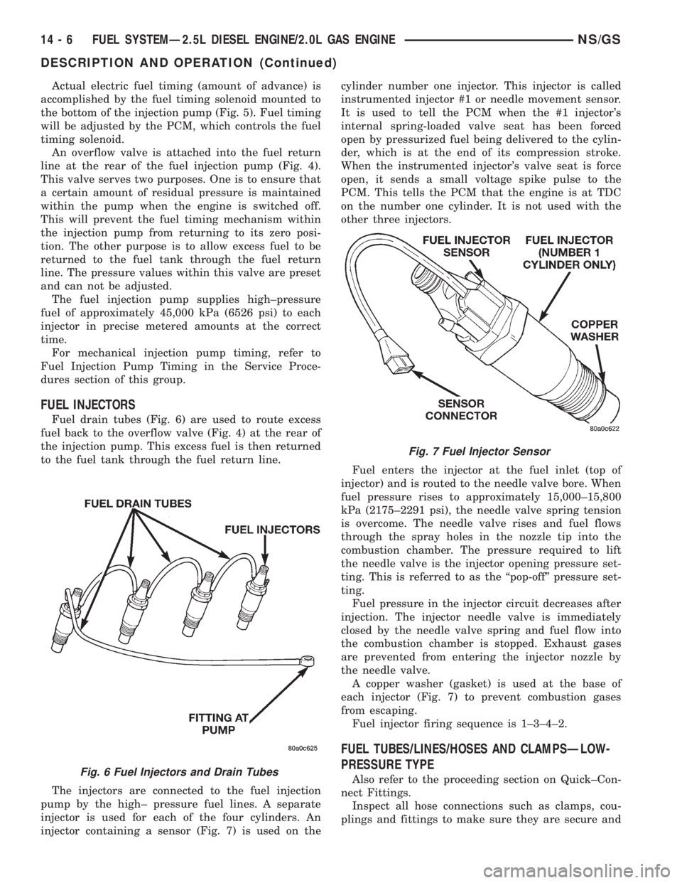
Fuel drain tubes (Fig. 6) are used to route excess
fuel back to the overflow valve (Fig. 4) at the rear of
the injection pump. This excess fuel is then returned
to the fuel tank through the fuel return line.
The injectors are connected to the fuel injection
pump by the high± pressure fuel lines. A separate
injector is used for each of the four cylinders. An
injector containing a sensor (Fig. 7) is used on thecylinder number one injector. This injector is called
instrumented injector #1 or needle movement sensor.
It is used to tell the PCM when the #1 injector's
internal spring-loaded valve seat has been forced
open by pressurized fuel being delivered to the cylin-
der, which is at the end of its compression stroke.
When the instrumented injector's valve seat is force
open, it sends a small voltage spike pulse to the
PCM. This tells the PCM that the engine is at TDC
on the number one cylinder. It is not used with the
other three injectors.
Fuel enters the injector at the fuel inlet (top of
injector) and is routed to the needle valve bore. When
fuel pressure rises to approximately 15,000±15,800
kPa (2175±2291 psi), the needle valve spring tension
is overcome. The needle valve rises and fuel flows
through the spray holes in the nozzle tip into the
combustion chamber. The pressure required to lift
the needle valve is the injector opening pressure set-
ting. This is referred to as the ªpop-offº pressure set-
ting.
Fuel pressure in the injector circuit decreases after
injection. The injector needle valve is immediately
closed by the needle valve spring and fuel flow into
the combustion chamber is stopped. Exhaust gases
are prevented from entering the injector nozzle by
the needle valve.
A copper washer (gasket) is used at the base of
each injector (Fig. 7) to prevent combustion gases
from escaping.
Fuel injector firing sequence is 1±3±4±2.
FUEL TUBES/LINES/HOSES AND CLAMPSÐLOW-
PRESSURE TYPE
Also refer to the proceeding section on Quick±Con-
nect Fittings.
Inspect all hose connections such as clamps, cou-
plings and fittings to make sure they are secure andFig. 6 Fuel Injectors and Drain Tubes
Fig. 7 Fuel Injector Sensor
14 - 6 FUEL SYSTEMÐ2.5L DIESEL ENGINE/2.0L GAS ENGINENS/GS
DESCRIPTION AND OPERATION (Continued)
Page 1375 of 1938
leaks are not present. The component should be
replaced immediately if there is any evidence of deg-
radation that could result in failure.
Never attempt to repair a plastic fuel line/tube or a
quick±connect fitting. Replace complete line/tube as
necessary.
Avoid contact of any fuel tubes/hoses with other
vehicle components that could cause abrasions or
scuffing. Be sure that the fuel lines/tubes are prop-
erly routed to prevent pinching and to avoid heat
sources.
The lines/tubes/hoses are of a special construction.
If it is necessary to replace these lines/tubes/hoses,
use only original equipment type.
The hose clamps used to secure the rubber hoses
are of a special rolled edge construction. This con-
struction is used to prevent the edge of the clamp
from cutting into the hose. Only these rolled edge
type clamps may be used in this system. All other
types of clamps may cut into the hoses and cause
fuel leaks.
Where a rubber hose is joined to a metal tube
(staked), do not attempt to repair. Replace entire
line/tube assembly.
Use new original equipment type hose clamps.
Tighten hose clamps to 2 N´m (20 in. lbs.) torque.
QUICK-CONNECT FITTINGSÐLOW PRESSURE
TYPE
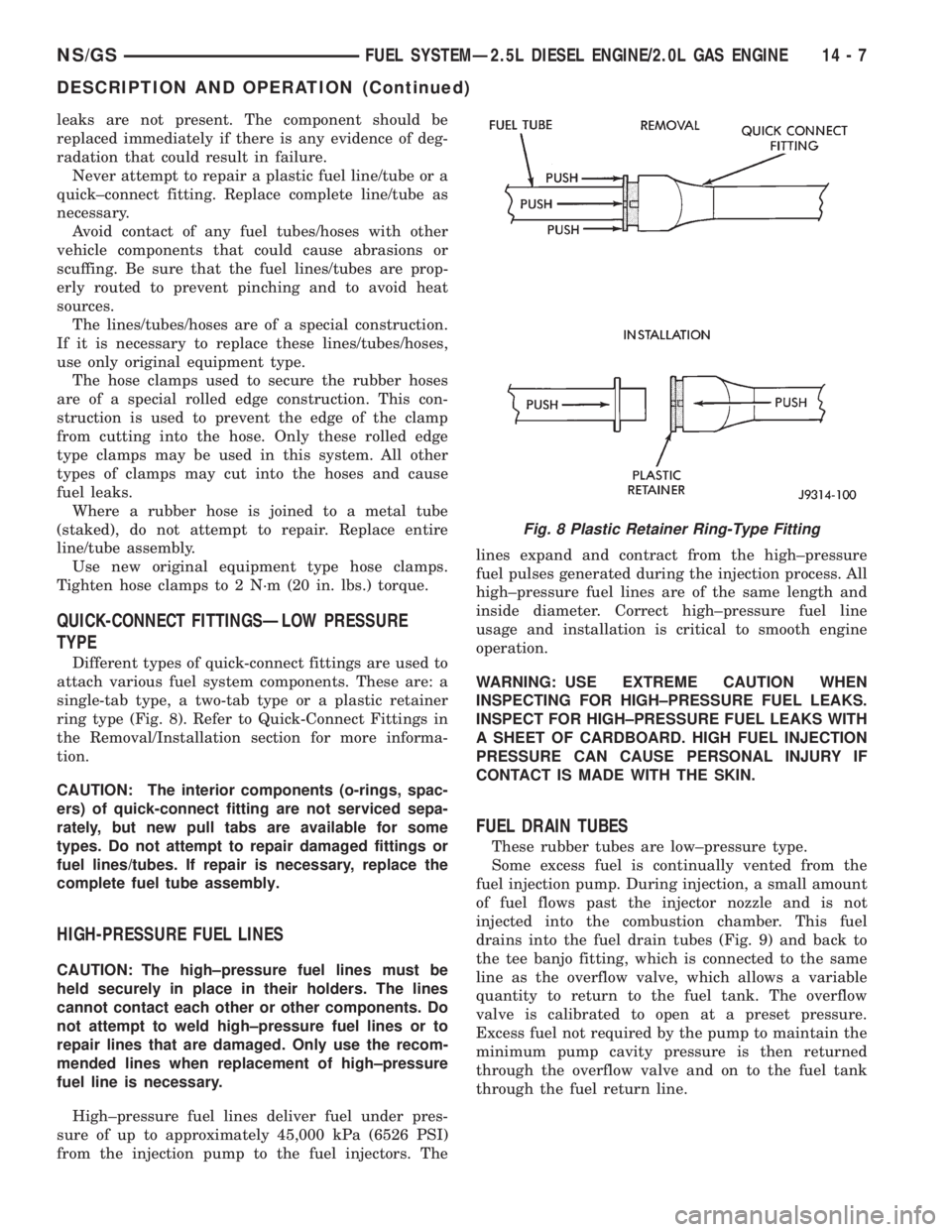
Different types of quick-connect fittings are used to
attach various fuel system components. These are: a
single-tab type, a two-tab type or a plastic retainer
ring type (Fig. 8). Refer to Quick-Connect Fittings in
the Removal/Installation section for more informa-
tion.
CAUTION: The interior components (o-rings, spac-
ers) of quick-connect fitting are not serviced sepa-
rately, but new pull tabs are available for some
types. Do not attempt to repair damaged fittings or
fuel lines/tubes. If repair is necessary, replace the
complete fuel tube assembly.
HIGH-PRESSURE FUEL LINES
CAUTION: The high±pressure fuel lines must be
held securely in place in their holders. The lines
cannot contact each other or other components. Do
not attempt to weld high±pressure fuel lines or to
repair lines that are damaged. Only use the recom-
mended lines when replacement of high±pressure
fuel line is necessary.
High±pressure fuel lines deliver fuel under pres-
sure of up to approximately 45,000 kPa (6526 PSI)
from the injection pump to the fuel injectors. Thelines expand and contract from the high±pressure
fuel pulses generated during the injection process. All
high±pressure fuel lines are of the same length and
inside diameter. Correct high±pressure fuel line
usage and installation is critical to smooth engine
operation.
WARNING: USE EXTREME CAUTION WHEN
INSPECTING FOR HIGH±PRESSURE FUEL LEAKS.
INSPECT FOR HIGH±PRESSURE FUEL LEAKS WITH
A SHEET OF CARDBOARD. HIGH FUEL INJECTION
PRESSURE CAN CAUSE PERSONAL INJURY IF
CONTACT IS MADE WITH THE SKIN.
FUEL DRAIN TUBES
These rubber tubes are low±pressure type.
Some excess fuel is continually vented from the
fuel injection pump. During injection, a small amount
of fuel flows past the injector nozzle and is not
injected into the combustion chamber. This fuel
drains into the fuel drain tubes (Fig. 9) and back to
the tee banjo fitting, which is connected to the same
line as the overflow valve, which allows a variable
quantity to return to the fuel tank. The overflow
valve is calibrated to open at a preset pressure.
Excess fuel not required by the pump to maintain the
minimum pump cavity pressure is then returned
through the overflow valve and on to the fuel tank
through the fuel return line.
Fig. 8 Plastic Retainer Ring-Type Fitting
NS/GSFUEL SYSTEMÐ2.5L DIESEL ENGINE/2.0L GAS ENGINE 14 - 7
DESCRIPTION AND OPERATION (Continued)
Page 1379 of 1938
the intake manifold. Refer to Group 11, Exhaust Sys-
tem and Intake Manifold for information.
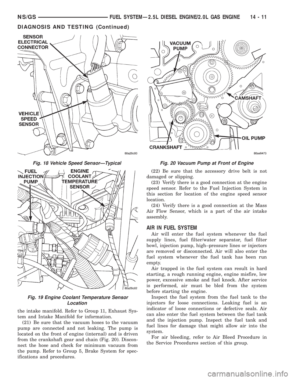
(21) Be sure that the vacuum hoses to the vacuum
pump are connected and not leaking. The pump is
located on the front of engine (internal) and is driven
from the crankshaft gear and chain (Fig. 20). Discon-
nect the hose and check for minimum vacuum from
the pump. Refer to Group 5, Brake System for spec-
ifications and procedures.(22) Be sure that the accessory drive belt is not
damaged or slipping.
(23) Verify there is a good connection at the engine
speed sensor. Refer to the Fuel Injection System in
this section for location of the engine speed sensor
location.
(24) Verify there is a good connection at the Mass
Air Flow Sensor, which is a part of the air intake
assembly.
AIR IN FUEL SYSTEM
Air will enter the fuel system whenever the fuel
supply lines, fuel filter/water separator, fuel filter
bowl, injection pump, high±pressure lines or injectors
are removed or disconnected. Air will also enter the
fuel system whenever the fuel tank has been run
empty.
Air trapped in the fuel system can result in hard
starting, a rough running engine, engine misfire, low
power, excessive smoke and fuel knock. After service
is performed, air must be bled from the system
before starting the engine.
Inspect the fuel system from the fuel tank to the
injectors for loose connections. Leaking fuel is an
indicator of loose connections or defective seals. Air
can also enter the fuel system between the fuel tank
and the injection pump. Inspect the fuel tank and
fuel lines for damage that might allow air into the
system.
For air bleeding, refer to Air Bleed Procedure in
the Service Procedures section of this group.
Fig. 18 Vehicle Speed SensorÐTypical
Fig. 19 Engine Coolant Temperature Sensor
Location
Fig. 20 Vacuum Pump at Front of Engine
NS/GSFUEL SYSTEMÐ2.5L DIESEL ENGINE/2.0L GAS ENGINE 14 - 11
DIAGNOSIS AND TESTING (Continued)
Page 1383 of 1938
²High±pressure fuel line connections are loosened
or lines replaced
²Initial engine start±up or start±up after an
extended period of no engine operation
²Running fuel tank empty
FUEL INJECTION PUMP BLEEDING
(1) If the fuel injection pump has been replaced,
air should be bled at the overflow valve before
attempting to start engine.
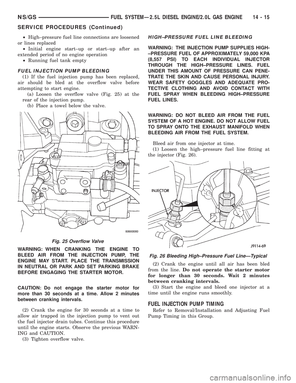
(a) Loosen the overflow valve (Fig. 25) at the
rear of the injection pump.
(b) Place a towel below the valve.
WARNING: WHEN CRANKING THE ENGINE TO
BLEED AIR FROM THE INJECTION PUMP, THE
ENGINE MAY START. PLACE THE TRANSMISSION
IN NEUTRAL OR PARK AND SET PARKING BRAKE
BEFORE ENGAGING THE STARTER MOTOR.
CAUTION: Do not engage the starter motor for
more than 30 seconds at a time. Allow 2 minutes
between cranking intervals.
(2) Crank the engine for 30 seconds at a time to
allow air trapped in the injection pump to vent out
the fuel injector drain tubes. Continue this procedure
until the engine starts. Observe the previous WARN-
ING and CAUTION.
(3) Tighten overflow valve.
HIGH±PRESSURE FUEL LINE BLEEDING
WARNING: THE INJECTION PUMP SUPPLIES HIGH-
±PRESSURE FUEL OF APPROXIMATELY 59,000 KPA
(8,557 PSI) TO EACH INDIVIDUAL INJECTOR
THROUGH THE HIGH±PRESSURE LINES. FUEL
UNDER THIS AMOUNT OF PRESSURE CAN PENE-
TRATE THE SKIN AND CAUSE PERSONAL INJURY.
WEAR SAFETY GOGGLES AND ADEQUATE PRO-
TECTIVE CLOTHING AND AVOID CONTACT WITH
FUEL SPRAY WHEN BLEEDING HIGH±PRESSURE
FUEL LINES.
WARNING: DO NOT BLEED AIR FROM THE FUEL
SYSTEM OF A HOT ENGINE. DO NOT ALLOW FUEL
TO SPRAY ONTO THE EXHAUST MANIFOLD WHEN
BLEEDING AIR FROM THE FUEL SYSTEM.
Bleed air from one injector at time.
(1) Loosen the high±pressure fuel line fitting at
the injector (Fig. 26).
(2) Crank the engine until all air has been bled
from the line.Do not operate the starter motor
for longer than 30 seconds. Wait 2 minutes
between cranking intervals.
(3) Start the engine and bleed one injector at a
time until the engine runs smoothly.
FUEL INJECTION PUMP TIMING
Refer to Removal/Installation and Adjusting Fuel
Pump Timing in this Group.
Fig. 25 Overflow Valve
Fig. 26 Bleeding High±Pressure Fuel LineÐTypical
NS/GSFUEL SYSTEMÐ2.5L DIESEL ENGINE/2.0L GAS ENGINE 14 - 15
SERVICE PROCEDURES (Continued)
Page 1391 of 1938
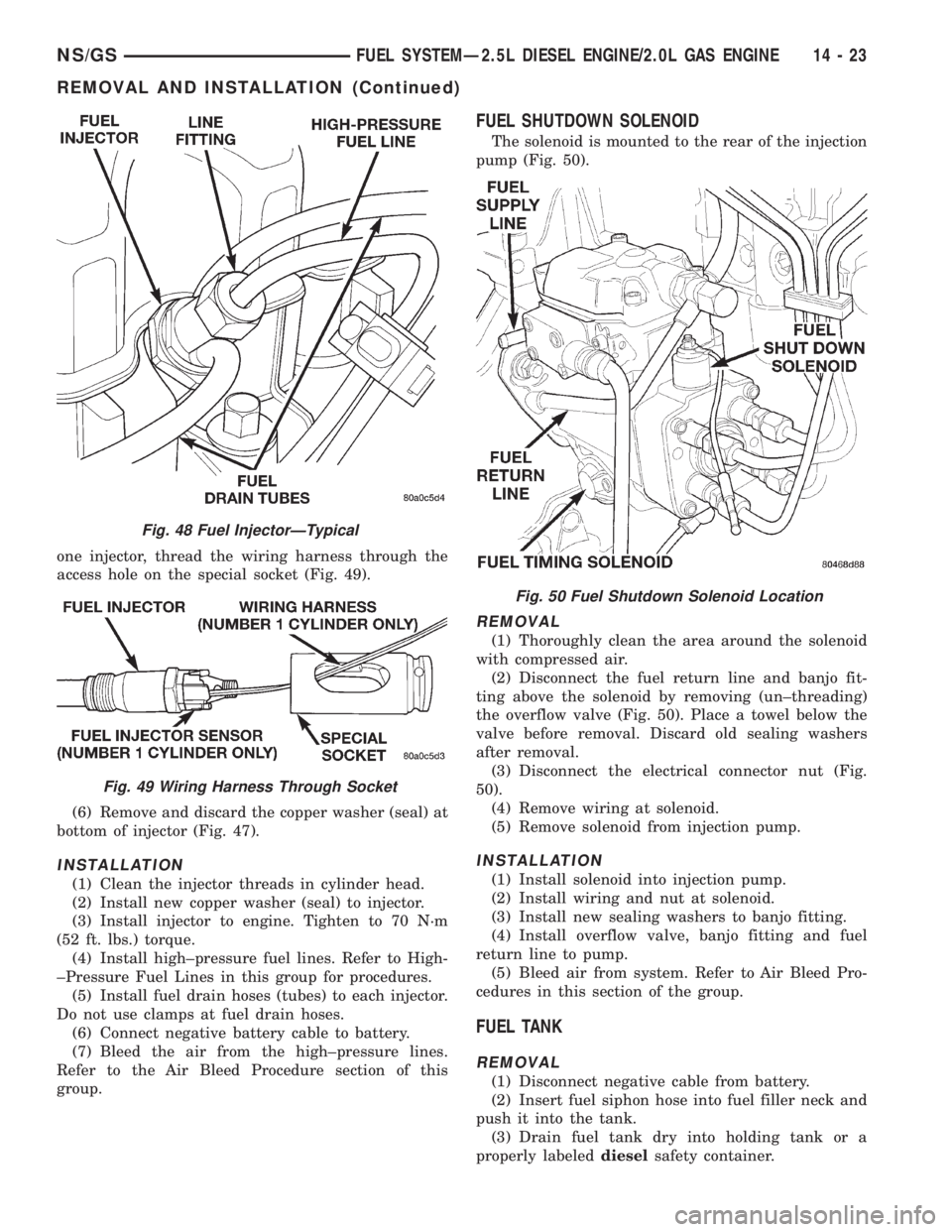
one injector, thread the wiring harness through the
access hole on the special socket (Fig. 49).
(6) Remove and discard the copper washer (seal) at
bottom of injector (Fig. 47).
INSTALLATION
(1) Clean the injector threads in cylinder head.
(2) Install new copper washer (seal) to injector.
(3) Install injector to engine. Tighten to 70 N´m
(52 ft. lbs.) torque.
(4) Install high±pressure fuel lines. Refer to High-
±Pressure Fuel Lines in this group for procedures.
(5) Install fuel drain hoses (tubes) to each injector.
Do not use clamps at fuel drain hoses.
(6) Connect negative battery cable to battery.
(7) Bleed the air from the high±pressure lines.
Refer to the Air Bleed Procedure section of this
group.
FUEL SHUTDOWN SOLENOID
The solenoid is mounted to the rear of the injection
pump (Fig. 50).
REMOVAL
(1) Thoroughly clean the area around the solenoid
with compressed air.
(2) Disconnect the fuel return line and banjo fit-
ting above the solenoid by removing (un±threading)
the overflow valve (Fig. 50). Place a towel below the
valve before removal. Discard old sealing washers
after removal.
(3) Disconnect the electrical connector nut (Fig.
50).
(4) Remove wiring at solenoid.
(5) Remove solenoid from injection pump.
INSTALLATION
(1) Install solenoid into injection pump.
(2) Install wiring and nut at solenoid.
(3) Install new sealing washers to banjo fitting.
(4) Install overflow valve, banjo fitting and fuel
return line to pump.
(5) Bleed air from system. Refer to Air Bleed Pro-
cedures in this section of the group.
FUEL TANK
REMOVAL
(1) Disconnect negative cable from battery.
(2) Insert fuel siphon hose into fuel filler neck and
push it into the tank.
(3) Drain fuel tank dry into holding tank or a
properly labeleddieselsafety container.
Fig. 48 Fuel InjectorÐTypical
Fig. 49 Wiring Harness Through Socket
Fig. 50 Fuel Shutdown Solenoid Location
NS/GSFUEL SYSTEMÐ2.5L DIESEL ENGINE/2.0L GAS ENGINE 14 - 23
REMOVAL AND INSTALLATION (Continued)
Page 1392 of 1938
(4) Raise vehicle on hoist.
(5) Disconnect both the fuel fill and fuel vent rub-
ber hoses at the fuel tank.
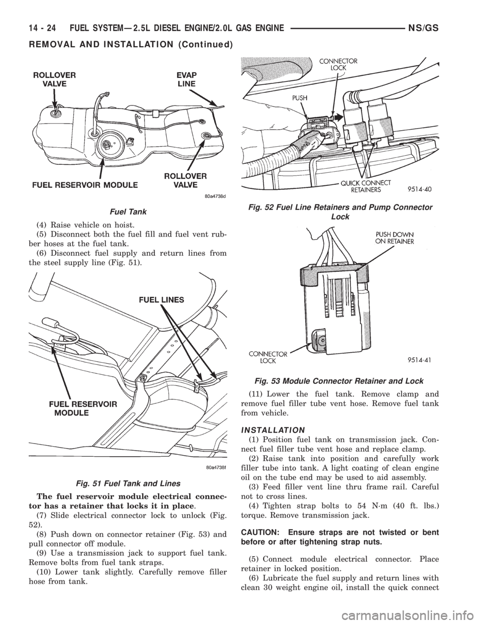
(6) Disconnect fuel supply and return lines from
the steel supply line (Fig. 51).
The fuel reservoir module electrical connec-
tor has a retainer that locks it in place.
(7) Slide electrical connector lock to unlock (Fig.
52).
(8) Push down on connector retainer (Fig. 53) and
pull connector off module.
(9) Use a transmission jack to support fuel tank.
Remove bolts from fuel tank straps.
(10) Lower tank slightly. Carefully remove filler
hose from tank.(11) Lower the fuel tank. Remove clamp and
remove fuel filler tube vent hose. Remove fuel tank
from vehicle.
INSTALLATION
(1) Position fuel tank on transmission jack. Con-
nect fuel filler tube vent hose and replace clamp.
(2) Raise tank into position and carefully work
filler tube into tank. A light coating of clean engine
oil on the tube end may be used to aid assembly.
(3) Feed filler vent line thru frame rail. Careful
not to cross lines.
(4) Tighten strap bolts to 54 N´m (40 ft. lbs.)
torque. Remove transmission jack.
CAUTION: Ensure straps are not twisted or bent
before or after tightening strap nuts.
(5) Connect module electrical connector. Place
retainer in locked position.
(6) Lubricate the fuel supply and return lines with
clean 30 weight engine oil, install the quick connect
Fuel Tank
Fig. 51 Fuel Tank and Lines
Fig. 52 Fuel Line Retainers and Pump Connector
Lock
Fig. 53 Module Connector Retainer and Lock
14 - 24 FUEL SYSTEMÐ2.5L DIESEL ENGINE/2.0L GAS ENGINENS/GS
REMOVAL AND INSTALLATION (Continued)
Page 1393 of 1938
fuel fitting. Refer to Tube/Fitting Assembly in the
Fuel Delivery section of this Group.
(7) Attach filler line to filler tube. Pull on connec-
tor to make sure of connection.
(8) Fill fuel tank, replace cap, and connect battery
negative cable.
FUEL RESERVOIR MODULE
REMOVAL
WARNING: THE FUEL RESERVOIR OF THE FUEL
MODULE DOES NOT EMPTY OUT WHEN THE TANK
IS DRAINED. THE FUEL IN THE RESERVOIR WILL
SPILL OUT WHEN THE MODULE IS REMOVED.
(1) Disconnect negative cable from battery.
(2) Insert fuel siphon hose into fuel filler neck and
push it into the tank.
(3) Drain fuel tank dry into holding tank or a
properly labeleddieselsafety container.
(4) Raise vehicle on hoist.
(5) Use a transmission jack to support the fuel
tank. Remove bolts from fuel tank straps. Lower
tank slightly.
(6) Clean area around fuel reservoir module and
tank to keep dirt and foreign material out of tank.
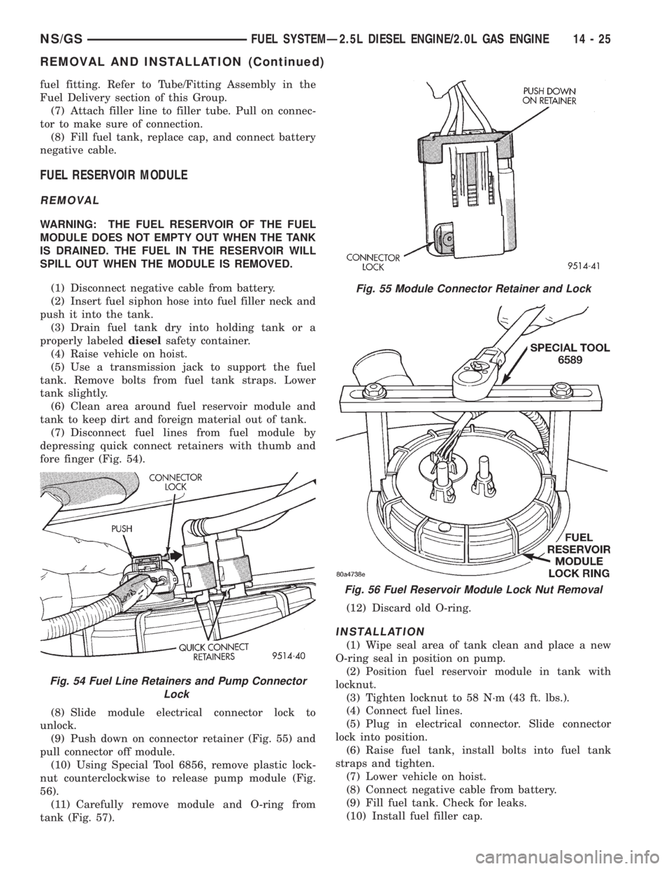
(7) Disconnect fuel lines from fuel module by
depressing quick connect retainers with thumb and
fore finger (Fig. 54).
(8) Slide module electrical connector lock to
unlock.
(9) Push down on connector retainer (Fig. 55) and
pull connector off module.
(10) Using Special Tool 6856, remove plastic lock-
nut counterclockwise to release pump module (Fig.
56).
(11) Carefully remove module and O-ring from
tank (Fig. 57).(12) Discard old O-ring.
INSTALLATION
(1) Wipe seal area of tank clean and place a new
O-ring seal in position on pump.
(2) Position fuel reservoir module in tank with
locknut.
(3) Tighten locknut to 58 N´m (43 ft. lbs.).
(4) Connect fuel lines.
(5) Plug in electrical connector. Slide connector
lock into position.
(6) Raise fuel tank, install bolts into fuel tank
straps and tighten.
(7) Lower vehicle on hoist.
(8) Connect negative cable from battery.
(9) Fill fuel tank. Check for leaks.
(10) Install fuel filler cap.
Fig. 54 Fuel Line Retainers and Pump Connector
Lock
Fig. 55 Module Connector Retainer and Lock
Fig. 56 Fuel Reservoir Module Lock Nut Removal
NS/GSFUEL SYSTEMÐ2.5L DIESEL ENGINE/2.0L GAS ENGINE 14 - 25
REMOVAL AND INSTALLATION (Continued)
Page 1395 of 1938
Be sure the lines are not contacting each
other or any other component.
(5) Tighten the clamp bracket bolts to 24 N´m (18
ft. lbs.) torque.
(6) Bleed air from the fuel system. Refer to the Air
Bleed Procedure section of this group.
SPECIFICATIONS
FUEL TANK CAPACITY
75 Liters (20.0 Gals.)
Nominal refill capacities are shown. A variation
may be observed from vehicle to vehicle due to man-
ufacturing tolerances, ambient temperatures and
refill procedures.
IDLE SPEED
900 rpm625 rpmwith engine at normal operat-
ing temperature.
FUEL INJECTOR FIRING SEQUENCE
1±3±4±2
FUEL SYSTEM PRESSURE
Peak Injection Pressure/Fuel Injection Pump
Operating Pressure:40,000±45,000 kPa (5801±
6526 psi).
Opening Pressure of Fuel Injector:
15,000±15,800 kPa (2175±2291 psi).
NS/GSFUEL SYSTEMÐ2.5L DIESEL ENGINE/2.0L GAS ENGINE 14 - 27
REMOVAL AND INSTALLATION (Continued)