1996 CHRYSLER VOYAGER Fuel tank
[x] Cancel search: Fuel tankPage 966 of 1938

Component/
GroundColor Location Fig.
Camshaft
Position Sensor
3.3L, 3.8LBK RT Side of
Engine9
Center Dome
LampBK At Lamp N/S
CHMSL RD Rear of CHMSL 21
Cigar Lighter BK Rear of Lighter 9
Clockspring C1 YL Rear of
Clockspring11
Clockspring C2 NAT Rear of
Clockspring11
Clutch Interlock
SwitchBK Top of Clutch
Pedal13
Controller
Anti-Lock BrakeBK RT Side of
Engine
CompartmentN/S
Crankcase Vent
HeaterAt Heater N/S
Crankshaft
Position SensorBK Rear of Engine 5, 6, 7,
9
D01 BK On Kick Panel 18
D02 BK On Kick Panel 18
Data Link
ConnectorBK LT of Steering
Column12
Downstream
Heated Oxygen
SensorBK Front Center of
Floor Pan16
Driver Airbag YL Rear of Airbag 11
E36 BK LT Frame Rail 2
E40 BK At Radiator Fan
ModuleN/S
E43 LT/GY LT Frame Rail 2
E69 BK LT Side of
Intake6, 7
E78 BK Near Throttle
Body9
EC1 Above RT
Vanity Mirror17
EGR Solenoid BK LT Rear of
Engine6, 9
Electric Wiper
De-Icer C1BK At Left Base of
Windshield11
Electric Wiper
De-Icer C2BK At Right Base
of Windshield11Component/
GroundColor Location Fig.
Engine Coolant
Temp Sensor
2.4LBK On Cylinder
BlockN/S
Engine Coolant
Temp Sensor
2.5BK On Cylinder
Head8
Engine Coolant
Temp Sensor
3.3L, 3.8LBK On Cylinder
BlockN/S
Engine Oil
Pressure SwitchGN On Cylinder
Block5, 6, 7,
8, 9
Engine Starter
MotorRear of Starter 5, 6, 7,
8, 9
EVAP/Purge
SolenoidBK RT Motor
Mount3
Evaporator
Temperature
SensorBK RT Side of
HVACN/S
F02 BK Near Throttle
Body9
F09 BK LT Side of
Intake6, 7
Front Blower
MotorBK At Motor 10
Front Blower
Motor Resistor
BlockBK RT Side Cowl 4
Front Cigar
LighterBK Rear of Lighter 9
Front Reading
Lamps/SwitchRD At Lamp 15
Front Washer
MotorBK Bottom of
Reservior4
Fuel Injection
PumpBK Near Pump 8
Fuel Injector #1 BK At Injector N/S
Fuel Injector #2 BK At Injector N/S
Fuel Injector #3 BK At Injector N/S
Fuel Injector #4 BK At Injector N/S
Fuel Injector #5 BK At injector N/S
Fuel Injector #6 BK At Injector N/S
Fuel Injectors
(2.0L)BK At Injectors 5
Fuel Pump
HeaterBK At Heater N/S
Fuel Pump
ModuleLT/GY Side of Fuel
Tank20
8W - 90 - 2 8W - 90 CONNECTOR/GROUND LOCATIONSNS/GS
DESCRIPTION AND OPERATION (Continued)
Page 995 of 1938

CONNECTOR/GROUND LOCATIONS
For items not shown in this section a N/S is placed
in the Fig. column.
Component/
GroundColor Location Fig.
A/C
Compressor
ClutchBK Top of A/C
Compressor5, 6, 7,
8, 9
A/C-Heater
Control Module
C1NAT Rear of Control 11
A/C-Heater
Control Module
C2BK Rear of Control 11
A/C Pressure
TransducerGY RT Side Cowl 3
A/C Zone Door
ActuatorNAT LT Side of
HVAC15
Airbag Control
Module C1YL Rear of I.P.
Center Stack12
Airbag Contol
Module C2BK Rear of I.P.
Center Stack12
All Wheel Drive
SolenoidBK Near Fuel Tank 20
Ambient
Temperature
SensorGY On Radiator
Closure Panel4
Ash Receiver
LampRD At Lamp 10
Automatic
Day/Night MirrorBK At Mirror 17
B01 BK RT Kick Panel 18
B02 BK RT Kick Panel 18
B03 BK LT Kick Panel 18
B09 BK Under Seat 16
B17 BK LT Quarter
Panel21
B23 BK RT of Steering
Column13
B33 BK LT Frame Rail 2
B56 BK Under Seat 16
B70 LT/GY LT Frame Rail 2
B75 BL Bottom of RT
B-Pillar14
B98 BK Rear of RT Tail
LampN/SComponent/
GroundColor Location Fig.
B99 BK Rear of LT Tail
LampN/S
B120 BK LT Kick Panel N/S
Backup Lamp
Switch (M/T)BK On
Transmission5, 6, 8
Blend Door
ActuatorNAT LT Side of
HVAC15
Body Control
Module C1NAT On Junction
Block12
Body Control
Module C2NAT On Junction
Block12
Brake Pressure
SwitchBK On Master
Cylinder2
C19 At Top Center
of Windshield17
C20 Bottom of RT
B-PillarN/S
Camshaft
Position Sensor
2.4LBK Rear of
Cylinder Head6, 7
Camshaft
Position Sensor
3.3L, 3.8LBK RT Side of
Engine9
Center Dome
LampBK At Lamp N/S
CHMSL RD Rear of CHMSL 23
Clockspring C1 YL Rear of
Clockspring11
Clockspring C2 NAT Rear of
Clockspring11
Clutch Switch BK Top of Clutch
Pedal13
Controller
Anti-Lock BrakeBK LT Side of
Engine
CompartmentN/S
Crankshaft
Position SensorBK Rear of Engine 5, 6, 7,
9
D01 BK On Kick Panel 19
D02 BK On Kick Panel 19
Data Link
ConnectorBK LT of Steering
Column12
NS/GS8W - 90 CONNECTOR/GROUND LOCATIONS 8W - 90 - 31
DESCRIPTION AND OPERATION (Continued)
Page 996 of 1938

Component/
GroundColor Location Fig.
Downstream
Heated Oxygen
SensorBK Front Center of
Floor Pan16
Driver Airbag YL Rear of Airbag 11
E36 BK LT Frame Rail 2
E40 BK At Radiator Fan
ModuleN/S
E43 LT/GY LT Frame Rail 2
E69 BK LT Side of
Intake6, 7
E78 BK Near Throttle
Body9
EC1 At Top Center
of Windshield17
EGR Solenoid BK LT Rear of
Engine6, 9
Electric Wiper
De-Icer C1BK At Right Base
of Windshield11
Electric Wiper
De-Icer C2BK At Left Base of
Windshield11
Engine Coolant
Temp Sensor
2.4LBK On Cylinder
BlockN/S
Engine Coolant
Temp Sensor
3.3L, 3.8LBK On Cylinder
BlockN/S
Engine Oil
Pressure SwitchGN On Cylinder
Block5, 6, 7,
8, 9
Engine Starter
MotorRear of Starter 5, 6, 7,
8, 9
EVAP/Purge
SolenoidBK RT Motor
Mount3
Evaporator
Temperature
SensorBK RT Side of
HVACN/S
F02 BK Near Throttle
Body9
F09 BK LT Side of
Intake6, 7
Front Blower
MotorBK At Motor 10
Front Blower
Motor Resistor
BlockBK LT Side of
Engine2
Front Cigar
LighterBK Rear of Lighter 11Component/
GroundColor Location Fig.
Front Reading
Lamps/SwitchBL At Lamp 17
Front Washer
MotorBK Bottom of
Reservior4
Fuel Injector #1 BK At Injector N/S
Fuel Injector #2 BK At Injector N/S
Fuel Injector #3 BK At Injector N/S
Fuel Injector #4 BK At Injector N/S
Fuel Injector #5 BK At Injector N/S
Fuel Injector #6 BK At Injector N/S
Fuel Pump
ModuleGY Side of Fuel
Tank20
G100 LT Frame Rail 3
G101 2.4L Rear of
Cylinder Head6, 7
G101 3.3L, 3.8L Rear of
Cylinder Block9
G102 LT Frame Rail 3
G103 2.4L Rear of
Cylinder Head6, 7
G103 3.3L, 3.8L Rear of
Cylinder Block9
G104 Near T/O for
RT HeadlampN/S
G200 Left of I.P.
Center Stack10
G201 I.P. Center
Support10
G202 I.P. Center
Support10
G204 I.P. Center
Support10
G300 BK LT Kick Panel 13
G301 RT Kick Panel 13, 14
G302 BK LT Quarter
Panel21
G400 BK In Liftgate 23
Generator BK Rear of
Generator5, 6, 7,
8, 9
Glove Box
LampBL Rear of Glove
Box11
Headlamp
Dimmer SwitchBK Part of
Multifunction
Switch11
8W - 90 - 32 8W - 90 CONNECTOR/GROUND LOCATIONSNS/GS
DESCRIPTION AND OPERATION (Continued)
Page 1025 of 1938
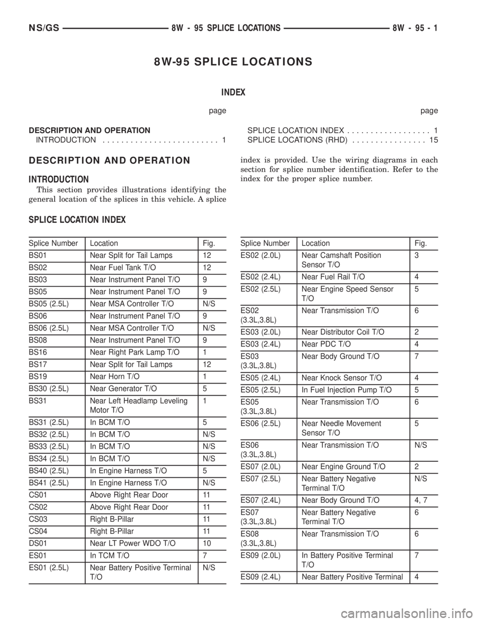
8W-95 SPLICE LOCATIONS
INDEX
page page
DESCRIPTION AND OPERATION
INTRODUCTION......................... 1SPLICE LOCATION INDEX.................. 1
SPLICE LOCATIONS (RHD)................ 15
DESCRIPTION AND OPERATION
INTRODUCTION
This section provides illustrations identifying the
general location of the splices in this vehicle. A spliceindex is provided. Use the wiring diagrams in each
section for splice number identification. Refer to the
index for the proper splice number.
SPLICE LOCATION INDEX
Splice Number Location Fig.
BS01 Near Split for Tail Lamps 12
BS02 Near Fuel Tank T/O 12
BS03 Near Instrument Panel T/O 9
BS05 Near Instrument Panel T/O 9
BS05 (2.5L) Near MSA Controller T/O N/S
BS06 Near Instrument Panel T/O 9
BS06 (2.5L) Near MSA Controller T/O N/S
BS08 Near Instrument Panel T/O 9
BS16 Near Right Park Lamp T/O 1
BS17 Near Split for Tail Lamps 12
BS19 Near Horn T/O 1
BS30 (2.5L) Near Generator T/O 5
BS31 Near Left Headlamp Leveling
Motor T/O1
BS31 (2.5L) In BCM T/O 5
BS32 (2.5L) In BCM T/O N/S
BS33 (2.5L) In BCM T/O N/S
BS34 (2.5L) In BCM T/O N/S
BS40 (2.5L) In Engine Harness T/O 5
BS41 (2.5L) In Engine Harness T/O N/S
CS01 Above Right Rear Door 11
CS02 Above Right Rear Door 11
CS03 Right B-Pillar 11
CS04 Right B-Pillar 11
DS01 Near LT Power WDO T/O 10
ES01 In TCM T/O 7
ES01 (2.5L) Near Battery Positive Terminal
T/ON/SSplice Number Location Fig.
ES02 (2.0L) Near Camshaft Position
Sensor T/O3
ES02 (2.4L) Near Fuel Rail T/O 4
ES02 (2.5L) Near Engine Speed Sensor
T/O5
ES02
(3.3L,3.8L)Near Transmission T/O 6
ES03 (2.0L) Near Distributor Coil T/O 2
ES03 (2.4L) Near PDC T/O 4
ES03
(3.3L,3.8L)Near Body Ground T/O 7
ES05 (2.4L) Near Knock Sensor T/O 4
ES05 (2.5L) In Fuel Injection Pump T/O 5
ES05
(3.3L,3.8L)Near Transmission T/O 6
ES06 (2.5L) Near Needle Movement
Sensor T/O5
ES06
(3.3L,3.8L)Near Transmission T/O N/S
ES07 (2.0L) Near Engine Ground T/O 2
ES07 (2.5L) Near Battery Negative
Terminal T/ON/S
ES07 (2.4L) Near Body Ground T/O 4, 7
ES07
(3.3L,3.8L)Near Battery Negative
Terminal T/O6
ES08
(3.3L,3.8L)Near Transmission T/O 6
ES09 (2.0L) In Battery Positive Terminal
T/O7
ES09 (2.4L) Near Battery Positive Terminal 4
NS/GS8W - 95 SPLICE LOCATIONS 8W - 95 - 1
Page 1039 of 1938
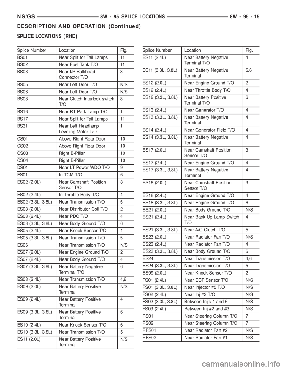
SPLICE LOCATIONS (RHD)
Splice Number Location Fig.
BS01 Near Split for Tail Lamps 11
BS02 Near Fuel Tank T/O 11
BS03 Near I/P Bulkhead
Connector T/O8
BS05 Near Left Door T/O N/S
BS06 Near Left Door T/O N/S
BS08 Near Clutch Interlock switch
T/O8
BS16 Near RT Park Lamp T/O 1
BS17 Near Split for Tail Lamps 11
BS31 Near Left Headlamp
Leveling Motor T/O1
CS01 Above Right Rear Door 10
CS02 Above Right Rear Door 10
CS03 Right B-Pillar 10
CS04 Right B-Pillar 10
DS01 Near LT Power WDO T/O 9
ES01 In TCM T/O 6
ES02 (2.0L) Near Camshaft Position
Sensor T/O3
ES02 (2.4L) In Throttle Body T/O 4
ES02 (3.3L, 3.8L) Near Transmission T/O 5
ES03 (2.0L) Near Distributor Coil T/O 2
ES03 (2.4L) Near PDC T/O 4
ES03 (3.3L, 3.8L) Near Body Ground T/O 6
ES05 (2.4L) Near Knock Sensor T/O 4
ES05 (3.3L, 3.8L) Near Transmission T/O 5
ES06 Near Transmission T/O N/S
ES07 (2.0L) Near Engine Ground T/O 2
ES07 (2.4L) Near Body Ground T/O 4
ES07 (3.3L, 3.8L) Near Battery Negative
Terminal T/O6
ES08 (2.4L) Near Transmission T/O 4,6
ES09 (2.0L) Near Battery Positive
TerminalN/S
ES09 (2.4L) Near Battery Positive
Terminal4
ES09 (3.3L, 3.8L) Near Battery Positive
Terminal6
ES10 (2.4L) Near Knock Sensor T/O 6
ES10 (3.3L, 3.8L) Near Transmission T/O 5
ES11 (2.0L) Near Battery Positive
TerminalN/SSplice Number Location Fig.
ES11 (2.4L) Near Battery Negative
Terminal T/O4
ES11 (3.3L, 3.8L) Near Battery Negative
Terminal5,6
ES12 (2.0L) Near Engine Ground T/O 2
ES12 (2.4L) Near Throttle Body T/O 4
ES12 (3.3L, 3.8L) Near Battery Positive
Terminal T/O6
ES13 (2.4L) Near Generator T/O 4
ES13 (3.3L, 3.8L) Near Battery Negative
Terminal4
ES14 (2.4L) Near Generator Field T/O 4
ES14 (3.3L, 3.8L) Near Battery Negative
Terminal4
ES17 (2.0L) Near Camshaft Position
Sensor T/O3
ES17 (2.4L) Near Engine Ground T/O 4
ES17 (3.3L, 3,8L) Near Battery Negative
Terminal4
ES18 (2.0L) Near Camshaft Position
Sensor T/O3
ES18 (2.4L) Near Engine Ground T/O 4
ES18 (3.3L, 3.8L) Near Engine Ground T/O 6
ES21 (2.0L) Near Body Ground T/O N/S
ES21 (2.4L) Near Back Up Lamp Switch
T/O4
ES21 (3.3L, 3.8L) Near A/C Clutch T/O 5
ES23 (2.0L) Near Radiator Fan T/O N/S
ES23 (2.4L) Near Radiator Fan T/O 4
ES23 (3.3L, 3.8L) Near Body Ground T/O 6
ES24 Near Transmission T/O 4,6
ES24 (3.3L, 3.8L) Near Transmission T/O 5
ES99 (2.0L) Near Knock Sensor T/O 2
FS01 (2.4L) Near ECT Sensor T/O N/S
FS01 (3.3L, 3.8L) Near Injector #5 T/O N/S
FS02 (2.4L) Near Inj #2 T/O N/S
FS02 (3.3L, 3.8L) Between Inj's 4 and 6 N/S
FS03 (2.4L) Between Inj #2 and #3 N/S
PS01 Near Steering Column T/O 7
PS02 Near Steering Column T/O 7
RFS01 Near Radiator Fan #2 N/S
RFS02 Near Radiator Fan #1 N/S
NS/GS8W - 95 SPLICE LOCATIONS 8W - 95 - 15
DESCRIPTION AND OPERATION (Continued)
Page 1221 of 1938
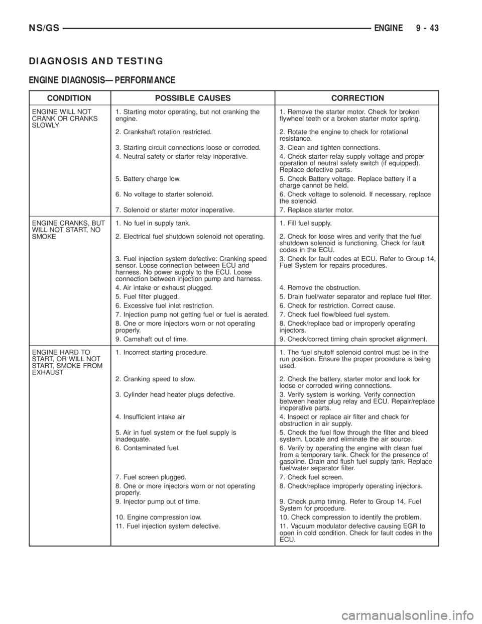
DIAGNOSIS AND TESTING
ENGINE DIAGNOSISÐPERFORMANCE
CONDITION POSSIBLE CAUSES CORRECTION
ENGINE WILL NOT
CRANK OR CRANKS
SLOWLY1. Starting motor operating, but not cranking the
engine.1. Remove the starter motor. Check for broken
flywheel teeth or a broken starter motor spring.
2. Crankshaft rotation restricted. 2. Rotate the engine to check for rotational
resistance.
3. Starting circuit connections loose or corroded. 3. Clean and tighten connections.
4. Neutral safety or starter relay inoperative. 4. Check starter relay supply voltage and proper
operation of neutral safety switch (if equipped).
Replace defective parts.
5. Battery charge low. 5. Check Battery voltage. Replace battery if a
charge cannot be held.
6. No voltage to starter solenoid. 6. Check voltage to solenoid. If necessary, replace
the solenoid.
7. Solenoid or starter motor inoperative. 7. Replace starter motor.
ENGINE CRANKS, BUT
WILL NOT START, NO
SMOKE1. No fuel in supply tank. 1. Fill fuel supply.
2. Electrical fuel shutdown solenoid not operating. 2. Check for loose wires and verify that the fuel
shutdown solenoid is functioning. Check for fault
codes in the ECU.
3. Fuel injection system defective: Cranking speed
sensor. Loose connection between ECU and
harness. No power supply to the ECU. Loose
connection between injection pump and harness.3. Check for fault codes at ECU. Refer to Group 14,
Fuel System for repairs procedures.
4. Air intake or exhaust plugged. 4. Remove the obstruction.
5. Fuel filter plugged. 5. Drain fuel/water separator and replace fuel filter.
6. Excessive fuel inlet restriction. 6. Check for restriction. Correct cause.
7. Injection pump not getting fuel or fuel is aerated. 7. Check fuel flow/bleed fuel system.
8. One or more injectors worn or not operating
properly.8. Check/replace bad or improperly operating
injectors.
9. Camshaft out of time. 9. Check/correct timing chain sprocket alignment.
ENGINE HARD TO
START, OR WILL NOT
START, SMOKE FROM
EXHAUST1. Incorrect starting procedure. 1. The fuel shutoff solenoid control must be in the
run position. Ensure the proper procedure is being
used.
2. Cranking speed to slow. 2. Check the battery, starter motor and look for
loose or corroded wiring connections.
3. Cylinder head heater plugs defective. 3. Verify system is working. Verify connection
between heater plug relay and ECU. Repair/replace
inoperative parts.
4. Insufficient intake air 4. Inspect or replace air filter and check for
obstruction in air supply.
5. Air in fuel system or the fuel supply is
inadequate.5. Check the fuel flow through the filter and bleed
system. Locate and eliminate the air source.
6. Contaminated fuel. 6. Verify by operating the engine with clean fuel
from a temporary tank. Check for the presence of
gasoline. Drain and flush fuel supply tank. Replace
fuel/water separator filter.
7. Fuel screen plugged. 7. Check fuel screen.
8. One or more injectors worn or not operating
properly.8. Check/replace improperly operating injectors.
9. Injector pump out of time. 9. Check pump timing. Refer to Group 14, Fuel
System for procedure.
10. Engine compression low. 10. Check compression to identify the problem.
11. Fuel injection system defective. 11. Vacuum modulator defective causing EGR to
open in cold condition. Check for fault codes in the
ECU.
NS/GSENGINE 9 - 43
Page 1223 of 1938
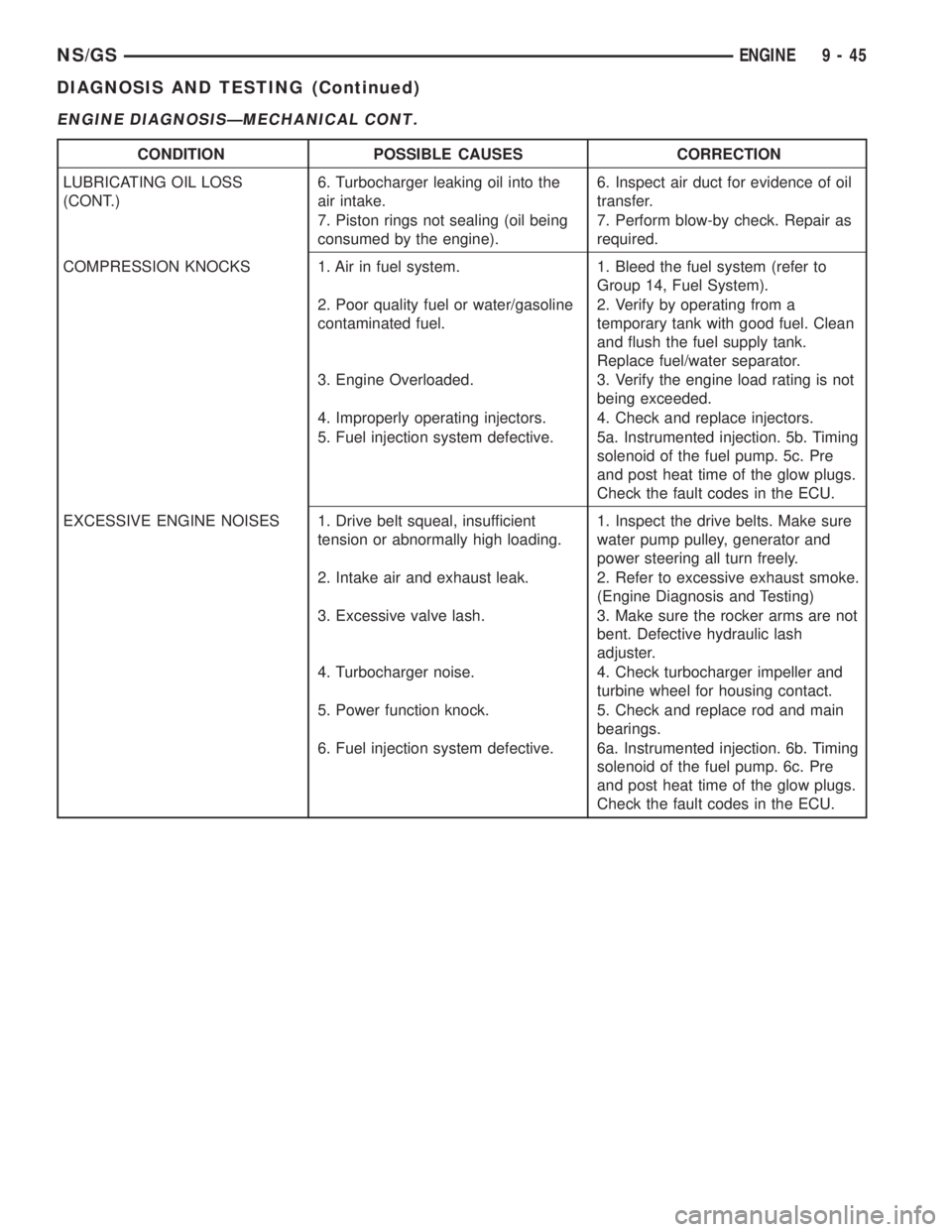
ENGINE DIAGNOSISÐMECHANICAL CONT.
CONDITION POSSIBLE CAUSES CORRECTION
LUBRICATING OIL LOSS
(CONT.)6. Turbocharger leaking oil into the
air intake.6. Inspect air duct for evidence of oil
transfer.
7. Piston rings not sealing (oil being
consumed by the engine).7. Perform blow-by check. Repair as
required.
COMPRESSION KNOCKS 1. Air in fuel system. 1. Bleed the fuel system (refer to
Group 14, Fuel System).
2. Poor quality fuel or water/gasoline
contaminated fuel.2. Verify by operating from a
temporary tank with good fuel. Clean
and flush the fuel supply tank.
Replace fuel/water separator.
3. Engine Overloaded. 3. Verify the engine load rating is not
being exceeded.
4. Improperly operating injectors. 4. Check and replace injectors.
5. Fuel injection system defective. 5a. Instrumented injection. 5b. Timing
solenoid of the fuel pump. 5c. Pre
and post heat time of the glow plugs.
Check the fault codes in the ECU.
EXCESSIVE ENGINE NOISES 1. Drive belt squeal, insufficient
tension or abnormally high loading.1. Inspect the drive belts. Make sure
water pump pulley, generator and
power steering all turn freely.
2. Intake air and exhaust leak. 2. Refer to excessive exhaust smoke.
(Engine Diagnosis and Testing)
3. Excessive valve lash. 3. Make sure the rocker arms are not
bent. Defective hydraulic lash
adjuster.
4. Turbocharger noise. 4. Check turbocharger impeller and
turbine wheel for housing contact.
5. Power function knock. 5. Check and replace rod and main
bearings.
6. Fuel injection system defective. 6a. Instrumented injection. 6b. Timing
solenoid of the fuel pump. 6c. Pre
and post heat time of the glow plugs.
Check the fault codes in the ECU.
NS/GSENGINE 9 - 45
DIAGNOSIS AND TESTING (Continued)
Page 1233 of 1938
(3) Install cylinder head cover, torque nuts to 14.7
N´m (132 in. lbs.).
(4) Install coolant pressure tank.
(5) Install breather hose.
(6) Install generator bracket, tighten bolts to 7
N´m (4 ft. lbs.).
(7) Connect the service valves to the A/C compres-
sor ports, if equipped with air conditioning.
(8) Connect battery cable.
VALVE SPRINGSÐCYLINDER HEAD NOT
REMOVED
This procedure can be done with the engine cylin-
der head installed on the block.
REMOVAL
Each valve spring is held in place by a retainer
and a set of conical valve locks. The locks can be
removed only by compressing the valve spring.
(1) Remove the engine cylinder head cover, refer to
cylinder head cover removal in this section.
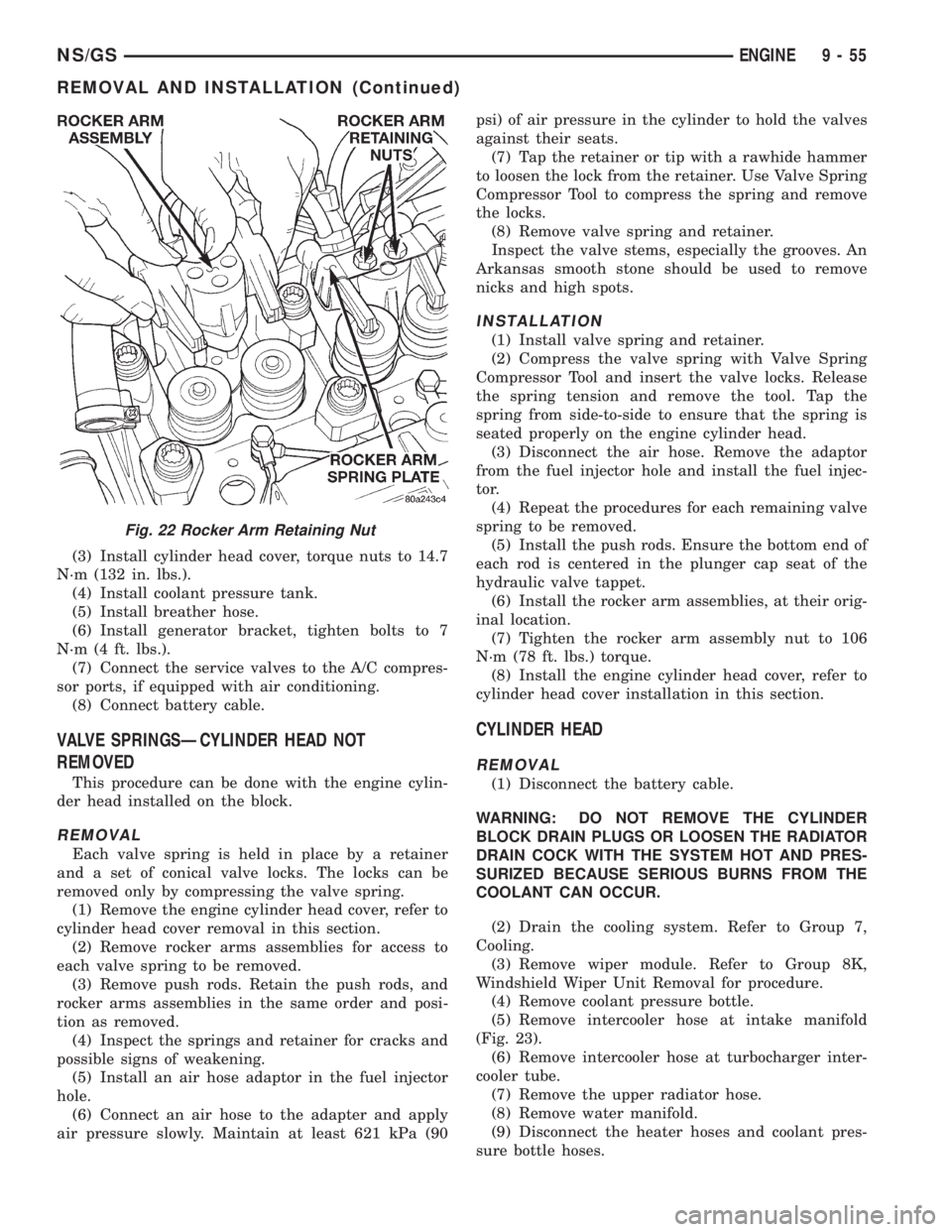
(2) Remove rocker arms assemblies for access to
each valve spring to be removed.
(3) Remove push rods. Retain the push rods, and
rocker arms assemblies in the same order and posi-
tion as removed.
(4) Inspect the springs and retainer for cracks and
possible signs of weakening.
(5) Install an air hose adaptor in the fuel injector
hole.
(6) Connect an air hose to the adapter and apply
air pressure slowly. Maintain at least 621 kPa (90psi) of air pressure in the cylinder to hold the valves
against their seats.
(7) Tap the retainer or tip with a rawhide hammer
to loosen the lock from the retainer. Use Valve Spring
Compressor Tool to compress the spring and remove
the locks.
(8) Remove valve spring and retainer.
Inspect the valve stems, especially the grooves. An
Arkansas smooth stone should be used to remove
nicks and high spots.
INSTALLATION
(1) Install valve spring and retainer.
(2) Compress the valve spring with Valve Spring
Compressor Tool and insert the valve locks. Release
the spring tension and remove the tool. Tap the
spring from side-to-side to ensure that the spring is
seated properly on the engine cylinder head.
(3) Disconnect the air hose. Remove the adaptor
from the fuel injector hole and install the fuel injec-
tor.
(4) Repeat the procedures for each remaining valve
spring to be removed.
(5) Install the push rods. Ensure the bottom end of
each rod is centered in the plunger cap seat of the
hydraulic valve tappet.
(6) Install the rocker arm assemblies, at their orig-
inal location.
(7) Tighten the rocker arm assembly nut to 106
N´m (78 ft. lbs.) torque.
(8) Install the engine cylinder head cover, refer to
cylinder head cover installation in this section.
CYLINDER HEAD
REMOVAL
(1) Disconnect the battery cable.
WARNING: DO NOT REMOVE THE CYLINDER
BLOCK DRAIN PLUGS OR LOOSEN THE RADIATOR
DRAIN COCK WITH THE SYSTEM HOT AND PRES-
SURIZED BECAUSE SERIOUS BURNS FROM THE
COOLANT CAN OCCUR.
(2) Drain the cooling system. Refer to Group 7,
Cooling.
(3) Remove wiper module. Refer to Group 8K,
Windshield Wiper Unit Removal for procedure.
(4) Remove coolant pressure bottle.
(5) Remove intercooler hose at intake manifold
(Fig. 23).
(6) Remove intercooler hose at turbocharger inter-
cooler tube.
(7) Remove the upper radiator hose.
(8) Remove water manifold.
(9) Disconnect the heater hoses and coolant pres-
sure bottle hoses.
Fig. 22 Rocker Arm Retaining Nut
NS/GSENGINE 9 - 55
REMOVAL AND INSTALLATION (Continued)