1996 CHRYSLER VOYAGER Fuel tank
[x] Cancel search: Fuel tankPage 1396 of 1938
FUEL DELIVERY SYSTEMÐ2.0L ENGINE
INDEX
page page
DESCRIPTION AND OPERATION
ELECTRIC FUEL PUMP.................. 28
FUEL DELIVERY SYSTEM................ 28
FUEL INJECTORS...................... 28
FUEL LEVEL SENSOR................... 28
FUEL PRESSURE REGULATOR........... 28
FUEL PUMP MODULE................... 28
FUEL TANK........................... 28
PRESSURE-VACUUM FILLER CAPÐ
2.0L ENGINE......................... 28
QUICK-CONNNECT FITTINGSÐ
2.0L ENGINE......................... 28
DIAGNOSIS AND TESTING
FUEL INJECTORSÐ2.0L ENGINE.......... 29
FUEL LEVEL SENSORÐ2.0L ENGINE....... 28
FUEL PUMP PRESSURE TESTÐ
2.0L ENGINE......................... 28SERVICE PROCEDURES
FUEL SYSTEM PRESSURE RELEASE
PROCEDUREÐ2.0L ENGINE............ 29
HOSES AND CLAMPSÐ2.0L ENGINE....... 29
QUICK-CONNNECT FITTINGSÐ2.0L ENGINE . 29
REMOVAL AND INSTALLATION
ACCELERATOR PEDAL.................. 31
FUEL FILTERÐ2.0L ENGINE.............. 29
FUEL INJECTORS...................... 30
FUEL LEVEL SENSORÐ2.0L ENGINE....... 30
FUEL PRESSURE REGULATORÐ
2.0L ENGINE......................... 29
FUEL PRESSURE REGULATORÐ
2.0L ENGINE......................... 29
FUEL PUMP MODULEÐ2.0L ENGINE....... 29
FUEL TANKÐ2.0L ENGINE............... 30
TORQUE SPECIFICATION................ 31
DESCRIPTION AND OPERATION
FUEL DELIVERY SYSTEM
Refer to the Fuel Delivery Sytem in the Fuel Deliv-
ery Section of group 14 for the 2.4/3.0/3.3/3.8L
engines for more information.
FUEL PUMP MODULE
Refer to the Fuel Pump Module for the 2.4/3.0/3.3/
3.8L engines in the Fuel Delivery System section of
group 14.
ELECTRIC FUEL PUMP
Refer to the Electric Fuel Pump for the 2.4/3.0/3.3/
3.8L engines in the Fuel Delivery System Section of
group 14 for more information.
FUEL LEVEL SENSOR
Refer to the Fuel Level Sensor for the 2.4/3.0/3.3/
3.8L engines in the Fuel Delivery System section of
group 14 for more information.
FUEL PRESSURE REGULATOR
Refer to the Fuel Pressure Regulator for the 2.4/
3.0/3.3/3.8L engines in the Fuel Delivery System sec-
tion of group 14 for more information.
FUEL INJECTORS
Refer to the Fuel Injectors for the 2.4/3.0/3.3/3.8L
engines in the Fuel Delivery System section of group
14 for more information.
FUEL TANK
Refer to the Fuel Tank for the 2.4/3.0/3.3/3.8L
engines in the Fuel Delivery System section of group
14 for more information.
PRESSURE-VACUUM FILLER CAPÐ2.0L ENGINE
Refer to the Pressure-Vacuum Filler Cap for the
2.4/3.0/3.3/3.8L engines in the Fuel Delivery System
section of group 14 for more information.
QUICK-CONNNECT FITTINGSÐ2.0L ENGINE
Refer to the Quick Connect Fittings for the 2.4/3.0/
3.3/3.8L engines in the Fuel Delivery System section
of group 14 for more information.
DIAGNOSIS AND TESTING
FUEL PUMP PRESSURE TESTÐ2.0L ENGINE
Refer to the Fuel Pressure Test for the 2.4/3.0/3.3/
3.8L engines in the Fuel Delivery System section of
group 14 for more information.
FUEL LEVEL SENSORÐ2.0L ENGINE
Refer to the Fuel Level Sensor for the 2.4/3.0/3.3/
3.8L engines in the Fuel Delivery System section of
group 14 for more information.
14 - 28 FUEL SYSTEMÐ2.5L DIESEL ENGINE/2.0L GAS ENGINENS/GS
Page 1398 of 1938
FUEL LEVEL SENSORÐ2.0L ENGINE
Refer to the Fuel Pump Inlet Strainer for the 2.4/
3.0/3.3/3.8L engines under Removal and Installation
in the Fuel Delivery System section of group 14 for
more information.
FUEL TANKÐ2.0L ENGINE
Refer to the Fuel Tank for the 2.4/3.0/3.3/3.8L
engines under Removal and Installation in the Fuel
Delivery System section of group 14 for more infor-
mation.
FUEL INJECTORS
REMOVAL
(1) Disconnect negative cable from battery.
(2) Release fuel system pressure. Refer to Fuel
System Pressure Release procedure in this section.
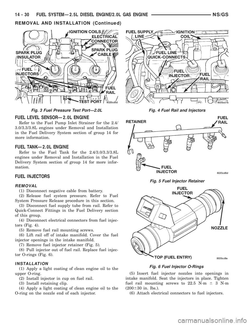
(3) Disconnect fuel supply tube from rail. Refer to
Quick-Connect Fittings in the Fuel Delivery section
of this group.
(4) Disconnect electrical connectors from fuel injec-
tors (Fig. 4).
(5) Remove fuel rail mounting screws.
(6) Lift rail off of intake manifold. Cover the fuel
injector openings in the intake manifold.
(7) Remove fuel injector retainer (Fig. 5).
(8) Pull injector out of fuel rail. Replace fuel injec-
tor O-rings (Fig. 6).
INSTALLATION
(1) Apply a light coating of clean engine oil to the
upper O-ring.
(2) Install injector in cup on fuel rail.
(3) Install retaining clip.
(4) Apply a light coating of clean engine oil to the
O-ring on the nozzle end of each injector.(5) Insert fuel injector nozzles into openings in
intake manifold. Seat the injectors in place. Tighten
fuel rail mounting screws to 22.5 N´m63 N´m
(200630 in. lbs.).
(6) Attach electrical connectors to fuel injectors.
Fig. 3 Fuel Pressure Test PortÐ2.0LFig. 4 Fuel Rail and Injectors
Fig. 5 Fuel Injector Retainer
Fig. 6 Fuel Injector O-Rings
14 - 30 FUEL SYSTEMÐ2.5L DIESEL ENGINE/2.0L GAS ENGINENS/GS
REMOVAL AND INSTALLATION (Continued)
Page 1399 of 1938
(7) Connect fuel supply tube to fuel rail. Refer to
Quick Connect Fittings in the Fuel Delivery Section
of this Group.
ACCELERATOR PEDAL
Refer to the Accelerator Pedal for the 2.4/3.0/.3.3/
3.8L engines under Removal and Installation in the
Fuel Delivery section of group 14 for more informa-
tion.
TORQUE SPECIFICATION
DESCRIPTION TORQUE
Accelerator Pedal to
Dash Nuts..............12N´m(105 in. lbs.)
Fuel Pump Module Locknut....58N´m(43ft.lbs.)
Fuel Tank Strap Bolts.........54N´m(40ftlbs.)
Fuel Rail Bolts.............23N´m(195 in. lbs.)
Ignition Coil Mounting Bolts . . . 11 N´m (95 in. lbs.)
Intake Manifold Bolts........11N´m(95in.lbs.)
Throttle Control Shield.......5.6N´m(50in.lbs.)
NS/GSFUEL SYSTEMÐ2.5L DIESEL ENGINE/2.0L GAS ENGINE 14 - 31
REMOVAL AND INSTALLATION (Continued)
Page 1407 of 1938

(20) Inspect the electrical connections at the
upstream and downstream heated oxygen sensors
(Fig. 25) and (Fig. 26).
(21) Inspect the fuel pump module electrical con-
nection at the fuel tank for corrosion or damage (Fig.27). Check for pinched, kinked or damaged fuel sup-
ply tube.
(22) Inspect the connections to the speed control
servo, if equipped. Refer to Group 8H, Vehicle Speed
Control.
(23) Inspect the connection at the battery temper-
ature sensor.
ASD AND FUEL PUMP RELAYSÐ2.0L ENGINE
Refer to the ASD and Fuel Pump Relays for 2.4/
3.0/3.3/3.8L engines under Diagnosis and Testing in
the Fuel Injection System section of group 14 for
more information.
MANIFOLD ABSOLUTE PRESSURE (MAP)
SENSORÐ2.0L ENGINE
To perform a complete test of the MAP sensor and
its circuitry, refer to the DRB scan tool and appropri-
ate Powertrain Diagnostics Procedures manual. To
test the MAP sensor only, refer to the following:
Fig. 23 Vehicle Speed Sensor
Fig. 24 Power Steering Pressure Switch
Fig. 25 Upstream Heated Oxygen Sensor
Fig. 26 Downstream Heated Oxygen Sensor
Fig. 27 Fuel Pump Module Electrical Connector
NS/GSFUEL SYSTEMÐ2.5L DIESEL ENGINE/2.0L GAS ENGINE 14 - 39
DIAGNOSIS AND TESTING (Continued)
Page 1757 of 1938
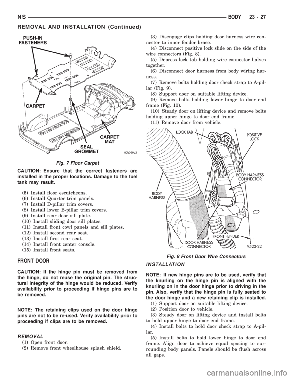
CAUTION: Ensure that the correct fasteners are
installed in the proper locations. Damage to the fuel
tank may result.
(5) Install floor escutcheons.
(6) Install Quarter trim panels.
(7) Install D-pillar trim covers.
(8) Install lower B-pillar trim covers.
(9) Install rear door sill plate.
(10) Install sliding door sill plates.
(11) Install front cowl panels and sill plates.
(12) Install second rear seat.
(13) Install first rear seat.
(14) Install front center console.
(15) Install front seats.
FRONT DOOR
CAUTION: If the hinge pin must be removed from
the hinge, do not reuse the original pin. The struc-
tural integrity of the hinge would be reduced. Verify
availability prior to proceeding if hinge pins are to
be removed.
NOTE: The retaining clips used on the door hinge
pins are not to be re-used. Verify availability prior to
proceeding if clips are to be removed.
REMOVAL
(1) Open front door.
(2) Remove front wheelhouse splash shield.(3) Disengage clips holding door harness wire con-
nector to inner fender brace.
(4) Disconnect positive lock slide on the side of the
wire connectors (Fig. 8).
(5) Depress lock tab holding wire connector halves
together.
(6) Disconnect door harness from body wiring har-
ness.
(7) Remove bolts holding door check strap to A-pil-
lar (Fig. 9).
(8) Support door on suitable lifting device.
(9) Remove bolts holding lower hinge to door end
frame (Fig. 10).
(10) Steady door on lifting device and remove bolts
holding upper hinge to door end frame.
(11) Remove door from vehicle.
INSTALLATION
NOTE: If new hinge pins are to be used, verify that
the knurling on the hinge pin is aligned with the
knurling on in the door hinge prior to driving in the
pin. Also, verify that the hinge pin is fully seated to
the door hinge and a new retaining clip is installed.
(1) Support door on suitable lifting device.
(2) Position door to vehicle.
(3) Steady door on lifting device and install bolts
to hold upper hinge to door end frame.
(4) Install bolts to hold door check strap to A-pil-
lar.
(5) Install bolts to hold lower hinge to door end
frame. Align door to achieve equal spacing to sur-
rounding body panels. Panels should be flush across
all gaps.
Fig. 7 Floor Carpet
Fig. 8 Front Door Wire Connectors
NSBODY 23 - 27
REMOVAL AND INSTALLATION (Continued)
Page 1911 of 1938
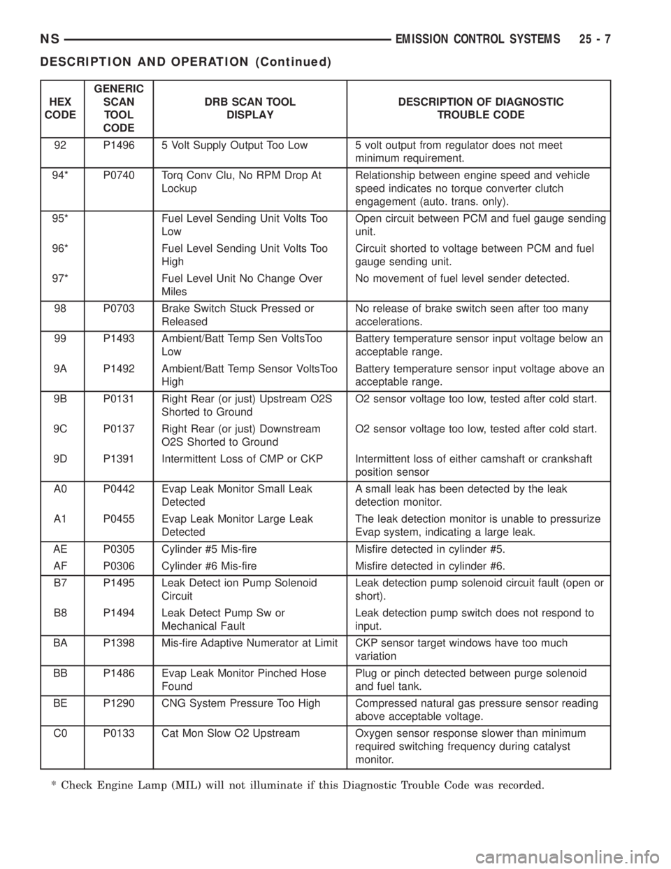
HEX
CODEGENERIC
SCAN
TOOL
CODEDRB SCAN TOOL
DISPLAYDESCRIPTION OF DIAGNOSTIC
TROUBLE CODE
92 P1496 5 Volt Supply Output Too Low 5 volt output from regulator does not meet
minimum requirement.
94* P0740 Torq Conv Clu, No RPM Drop At
LockupRelationship between engine speed and vehicle
speed indicates no torque converter clutch
engagement (auto. trans. only).
95* Fuel Level Sending Unit Volts Too
LowOpen circuit between PCM and fuel gauge sending
unit.
96* Fuel Level Sending Unit Volts Too
HighCircuit shorted to voltage between PCM and fuel
gauge sending unit.
97* Fuel Level Unit No Change Over
MilesNo movement of fuel level sender detected.
98 P0703 Brake Switch Stuck Pressed or
ReleasedNo release of brake switch seen after too many
accelerations.
99 P1493 Ambient/Batt Temp Sen VoltsToo
LowBattery temperature sensor input voltage below an
acceptable range.
9A P1492 Ambient/Batt Temp Sensor VoltsToo
HighBattery temperature sensor input voltage above an
acceptable range.
9B P0131 Right Rear (or just) Upstream O2S
Shorted to GroundO2 sensor voltage too low, tested after cold start.
9C P0137 Right Rear (or just) Downstream
O2S Shorted to GroundO2 sensor voltage too low, tested after cold start.
9D P1391 Intermittent Loss of CMP or CKP Intermittent loss of either camshaft or crankshaft
position sensor
A0 P0442 Evap Leak Monitor Small Leak
DetectedA small leak has been detected by the leak
detection monitor.
A1 P0455 Evap Leak Monitor Large Leak
DetectedThe leak detection monitor is unable to pressurize
Evap system, indicating a large leak.
AE P0305 Cylinder #5 Mis-fire Misfire detected in cylinder #5.
AF P0306 Cylinder #6 Mis-fire Misfire detected in cylinder #6.
B7 P1495 Leak Detect ion Pump Solenoid
CircuitLeak detection pump solenoid circuit fault (open or
short).
B8 P1494 Leak Detect Pump Sw or
Mechanical FaultLeak detection pump switch does not respond to
input.
BA P1398 Mis-fire Adaptive Numerator at Limit CKP sensor target windows have too much
variation
BB P1486 Evap Leak Monitor Pinched Hose
FoundPlug or pinch detected between purge solenoid
and fuel tank.
BE P1290 CNG System Pressure Too High Compressed natural gas pressure sensor reading
above acceptable voltage.
C0 P0133 Cat Mon Slow O2 Upstream Oxygen sensor response slower than minimum
required switching frequency during catalyst
monitor.
* Check Engine Lamp (MIL) will not illuminate if this Diagnostic Trouble Code was recorded.
NSEMISSION CONTROL SYSTEMS 25 - 7
DESCRIPTION AND OPERATION (Continued)
Page 1917 of 1938
EVAPORATIVE EMISSION CONTROLS
INDEX
page page
DESCRIPTION AND OPERATION
CRANKCASE VENT FILTER................ 16
EVAPORATION CONTROL SYSTEM......... 13
EVAPORATIVE (EVAP) CANISTER........... 13
LEAK DETECTION PUMP................. 14
POSITIVE CRANKCASE VENTILATION (PCV)
SYSTEMS............................ 15
PRESSURE-VACUUM FILLER CAP.......... 14
PROPORTIONAL PURGE SOLENOID......... 13ROLLOVER VALVE....................... 13
VEHICLE EMISSION CONTROL INFORMATION
LABEL............................... 16
DIAGNOSIS AND TESTING
LEAK DETECTION PUMP................. 16
PCV VALVE TEST....................... 16
REMOVAL AND INSTALLATION
LEAK DETECTION PUMP REPLACEMENT.... 16
ROLLOVER VALVES..................... 17
DESCRIPTION AND OPERATION
EVAPORATION CONTROL SYSTEM
The evaporation control system prevents the emis-
sion of fuel tank vapors into the atmosphere. When
fuel evaporates in the fuel tank, the vapors pass
through vent hoses or tubes to a charcoal filled evap-
orative canister. The canister temporarily holds the
vapors. The Powertrain Control Module (PCM) allows
intake manifold vacuum to draw vapors into the com-
bustion chambers during certain operating condi-
tions.
All engines use a duty cycle purge system. The
PCM controls vapor flow by operating the duty cycle
EVAP purge solenoid. Refer to Duty Cycle EVAP
Purge Solenoid in this section.
NOTE: The evaporative system uses specially man-
ufactured hoses. If they need replacement, only use
fuel resistant hose.
ROLLOVER VALVE
All vehicles have a rollover valve. The valve also
prevents fuel flow through the fuel tank vent valve
hoses should the vehicle rollover. All vehicles pass a
360É rollover.
The charcoal filled evaporative canister stores the
vapors. The rollover valve is not a serviceable item.
EVAPORATIVE (EVAP) CANISTER
All vehicles use a sealed, maintenance free, evapo-
rative (charcoal) canister. The canister is attached to
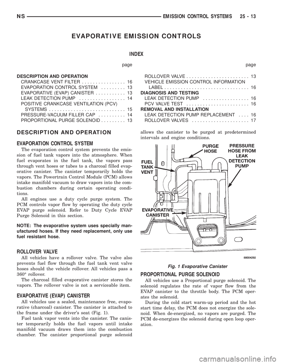
the frame under the driver's seat (Fig. 1).
Fuel tank vapor vents into the canister. The canis-
ter temporarily holds the fuel vapors until intake
manifold vacuum draws them into the combustion
chamber. The canister proportional purge solenoidallows the canister to be purged at predetermined
intervals and engine conditions.
PROPORTIONAL PURGE SOLENOID
All vehicles use a Proportional purge solenoid. The
solenoid regulates the rate of vapor flow from the
EVAP canister to the throttle body. The PCM oper-
ates the solenoid.
During the cold start warm-up period and the hot
start time delay, the PCM does not energize the sole-
noid. When de-energized, no vapors are purged. The
PCM de-energizes the solenoid during open loop oper-
ation.
Fig. 1 Evaporative Canister
NSEMISSION CONTROL SYSTEMS 25 - 13
Page 1918 of 1938
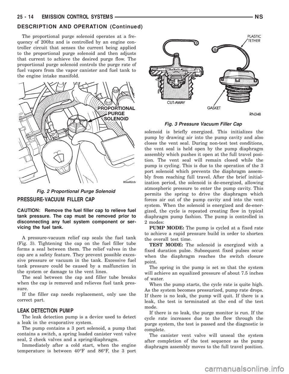
The proportional purge solenoid operates at a fre-
quency of 200hz and is controlled by an engine con-
troller circuit that senses the current being applied
to the proportional purge solenoid and then adjusts
that current to achieve the desired purge flow. The
proportional purge solenoid controls the purge rate of
fuel vapors from the vapor canister and fuel tank to
the engine intake manifold.
PRESSURE-VACUUM FILLER CAP
CAUTION: Remove the fuel filler cap to relieve fuel
tank pressure. The cap must be removed prior to
disconnecting any fuel system component or ser-
vicing the fuel tank.
A pressure-vacuum relief cap seals the fuel tank
(Fig. 3). Tightening the cap on the fuel filler tube
forms a seal between them. The relief valves in the
cap are a safety feature. They prevent possible exces-
sive pressure or vacuum in the tank. Excessive fuel
tank pressure could be caused by a malfunction in
the system or damage to the vent lines.
The seal between the cap and filler tube breaks
when the cap is removed and relieves fuel tank pres-
sure.
If the filler cap needs replacement, only use the
correct part.
LEAK DETECTION PUMP
The leak detection pump is a device used to detect
a leak in the evaporative system.
The pump contains a 3 port solenoid, a pump that
contains a switch, a spring loaded canister vent valve
seal, 2 check valves and a spring/diaphragm.
Immediately after a cold start, when the engine
temperature is between 40ÉF and 86ÉF, the 3 portsolenoid is briefly energized. This initializes the
pump by drawing air into the pump cavity and also
closes the vent seal. During non-test test conditions,
the vent seal is held open by the pump diaphragm
assembly which pushes it open at the full travel posi-
tion. The vent seal will remain closed while the
pump is cycling. This is due to the operation of the 3
port solenoid which prevents the diaphragm assem-
bly from reaching full travel. After the brief initial-
ization period, the solenoid is de-energized, allowing
atmospheric pressure to enter the pump cavity. This
permits the spring to drive the diaphragm which
forces air out of the pump cavity and into the vent
system. When the solenoid is energized and de-ener-
gized, the cycle is repeated creating flow in typical
diaphragm pump fashion. The pump is controlled in
2 modes:
PUMP MODE:The pump is cycled at a fixed rate
to achieve a rapid pressure build in order to shorten
the overall test time.
TEST MODE:The solenoid is energized with a
fixed duration pulse. Subsequent fixed pulses occur
when the diaphragm reaches the switch closure
point.
The spring in the pump is set so that the system
will achieve an equalized pressure of about 7.5 inches
of water.
When the pump starts, the cycle rate is quite high.
As the system becomes pressurized, pump rate drops.
If there is no leak, the pump will quit. If there is a
leak, the test is terminated at the end of the test
mode.
If there is no leak, the purge monitor is run. If the
cycle rate increases due to the flow through the
purge system, the test is passed and the diagnostic is
complete.
The canister vent valve will unseal the system
after completion of the test sequence as the pump
diaphragm assembly moves to the full travel position.
Fig. 2 Proportional Purge Solenoid
Fig. 3 Pressure Vacuum Filler Cap
25 - 14 EMISSION CONTROL SYSTEMSNS
DESCRIPTION AND OPERATION (Continued)