1996 CHRYSLER VOYAGER fuel pump
[x] Cancel search: fuel pumpPage 1119 of 1938
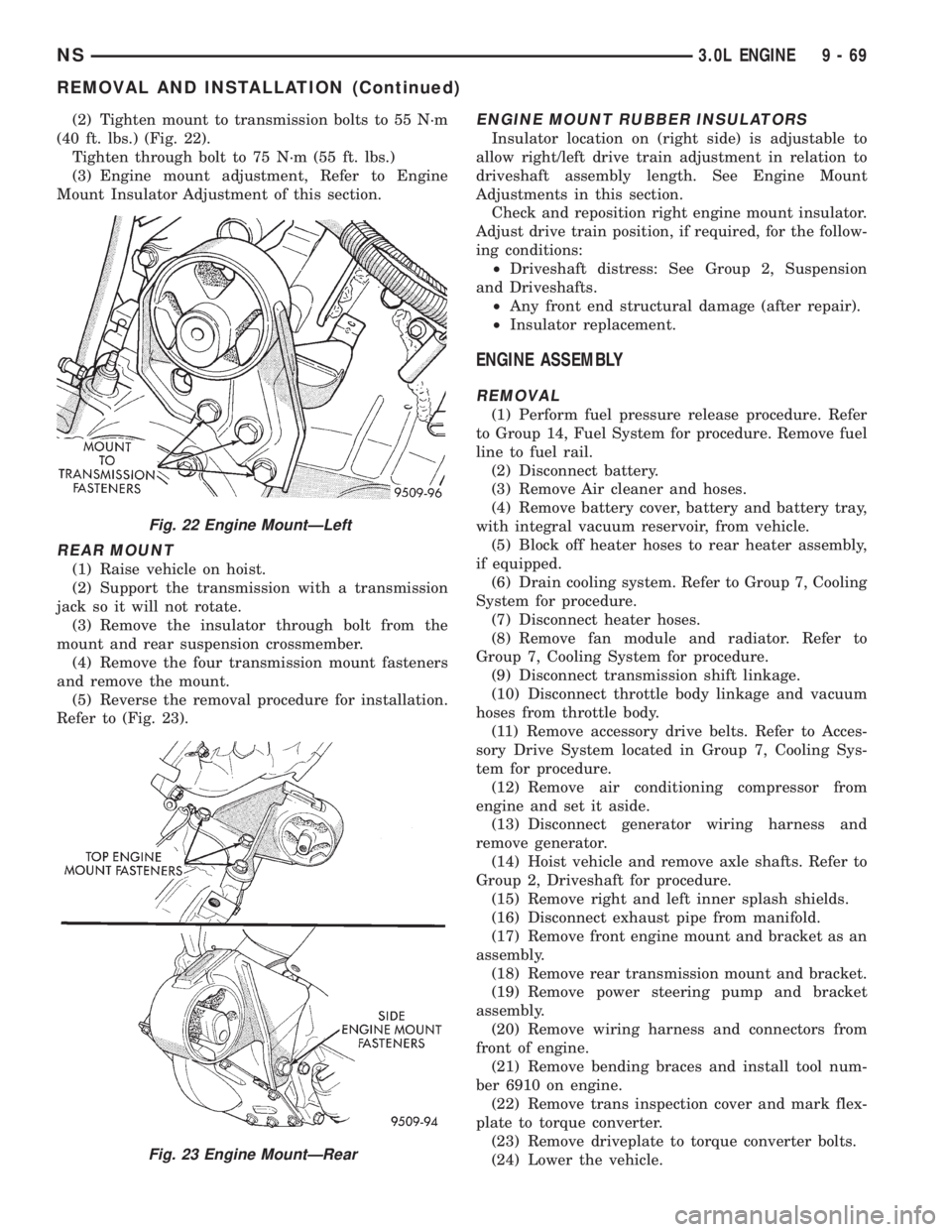
(2) Tighten mount to transmission bolts to 55 N´m
(40 ft. lbs.) (Fig. 22).
Tighten through bolt to 75 N´m (55 ft. lbs.)
(3) Engine mount adjustment, Refer to Engine
Mount Insulator Adjustment of this section.
REAR MOUNT
(1) Raise vehicle on hoist.
(2) Support the transmission with a transmission
jack so it will not rotate.
(3) Remove the insulator through bolt from the
mount and rear suspension crossmember.
(4) Remove the four transmission mount fasteners
and remove the mount.
(5) Reverse the removal procedure for installation.
Refer to (Fig. 23).
ENGINE MOUNT RUBBER INSULATORS
Insulator location on (right side) is adjustable to
allow right/left drive train adjustment in relation to
driveshaft assembly length. See Engine Mount
Adjustments in this section.
Check and reposition right engine mount insulator.
Adjust drive train position, if required, for the follow-
ing conditions:
²Driveshaft distress: See Group 2, Suspension
and Driveshafts.
²Any front end structural damage (after repair).
²Insulator replacement.
ENGINE ASSEMBLY
REMOVAL
(1) Perform fuel pressure release procedure. Refer
to Group 14, Fuel System for procedure. Remove fuel
line to fuel rail.
(2) Disconnect battery.
(3) Remove Air cleaner and hoses.
(4) Remove battery cover, battery and battery tray,
with integral vacuum reservoir, from vehicle.
(5) Block off heater hoses to rear heater assembly,
if equipped.
(6) Drain cooling system. Refer to Group 7, Cooling
System for procedure.
(7) Disconnect heater hoses.
(8) Remove fan module and radiator. Refer to
Group 7, Cooling System for procedure.
(9) Disconnect transmission shift linkage.
(10) Disconnect throttle body linkage and vacuum
hoses from throttle body.
(11) Remove accessory drive belts. Refer to Acces-
sory Drive System located in Group 7, Cooling Sys-
tem for procedure.
(12) Remove air conditioning compressor from
engine and set it aside.
(13) Disconnect generator wiring harness and
remove generator.
(14) Hoist vehicle and remove axle shafts. Refer to
Group 2, Driveshaft for procedure.
(15) Remove right and left inner splash shields.
(16) Disconnect exhaust pipe from manifold.
(17) Remove front engine mount and bracket as an
assembly.
(18) Remove rear transmission mount and bracket.
(19) Remove power steering pump and bracket
assembly.
(20) Remove wiring harness and connectors from
front of engine.
(21) Remove bending braces and install tool num-
ber 6910 on engine.
(22) Remove trans inspection cover and mark flex-
plate to torque converter.
(23) Remove driveplate to torque converter bolts.
(24) Lower the vehicle.
Fig. 22 Engine MountÐLeft
Fig. 23 Engine MountÐRear
NS3.0L ENGINE 9 - 69
REMOVAL AND INSTALLATION (Continued)
Page 1120 of 1938
(25) Remove ground straps to body.
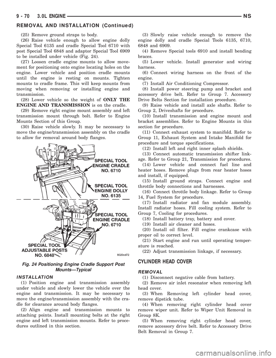
(26) Raise vehicle enough to allow engine dolly
Special Tool 6135 and cradle Special Tool 6710 with
post Special Tool 6848 and adaptor Special Tool 6909
to be installed under vehicle (Fig. 24).
(27) Loosen cradle engine mounts to allow move-
ment for positioning onto engine locating holes on the
engine. Lower vehicle and position cradle mounts
until the engine is resting on mounts. Tighten
mounts to cradle frame. This will keep mounts from
moving when removing or installing engine and
transmission.
(28) Lower vehicle so the weight ofONLY THE
ENGINE AND TRANSMISSIONis on the cradle.
(29) Remove right engine mount assembly and left
transmission mount through bolt. Refer to Engine
Mounts Section of this Group.
(30) Raise vehicle slowly. It may be necessary to
move the engine/transmission assembly on the cradle
to allow for removal around body flanges.
INSTALLATION
(1) Position engine and transmission assembly
under vehicle and slowly lower the vehicle over the
engine and transmission. It may be necessary to
move the engine/transmission assembly with the cra-
dle for clearance around body flanges.
(2) Align engine and transmission mounts to
attaching points. Install mounting bolts at the right
engine and left transmission mounts. Refer to proce-
dures outlined in this section.(3) Slowly raise vehicle enough to remove the
engine dolly and cradle Special Tools 6135, 6710,
6848 and 6909.
(4) Remove Special tools 6910 and install bending
braces.
(5) Lower vehicle. Install generator and wiring
harness.
(6) Connect wiring harness on the front of the
engine.
(7) Install Air Conditioning Compressor.
(8) Install power steering pump and bracket and
accessory drive belt. Refer to Group 7. Accessory
Drive Belts Section for installation procedure.
(9) Raise vehicle and install axle shafts. Refer to
Group 2, Driveshafts for procedure.
(10) Install transmission and engine mount and
bracket assemblies. Refer to Engine Mounts in this
section for procedure.
(11) Connect exhaust system to manifold. Refer to
Group 11, Exhaust System and Intake Manifold for
procedure and torque specifications.
(12) Install left and right inner splash shields.
(13) Connect automatic transmission shifter link-
age. Refer to Group 21, Transmission for procedures.
(14) Lower vehicle and connect fuel line and
heater hoses. Remove plugs from rear heater hoses
and install, if equipped.
(15) Install ground straps. Connect engine and
throttle body connections and harnesses.
(16) Connect throttle body linkage. Refer to Group
14, Fuel System for procedure.
(17) Install radiator and fan module assembly.
Install radiator hoses. Fill cooling system. Refer to
Group 7, Cooling for procedures.
(18) Install battery tray, battery and cover.
(19) Install air cleaner and hoses.
(20) Install oil filter. Fill engine crankcase with
proper oil to correct level.
(21) Start engine and run until operating temper-
ature is reached.
(22) Adjust transmission linkage, if necessary.
CYLINDER HEAD COVER
REMOVAL
(1) Disconnect negative cable from battery.
(2) Remove air inlet resonator when removing left
head cover.
(3) When Removing left cylinder head cover,
remove dipstick tube.
(4) When removing right cylinder head cover
remove wiper unit. Refer to Wiper Unit Removal in
Group 8K.
(5) When removing right cylinder head cover,
remove accessory drive belt. Refer to Accessory Drive
Belt Removal in Group 7.
Fig. 24 Positioning Engine Cradle Support Post
MountsÐTypical
9 - 70 3.0L ENGINENS
REMOVAL AND INSTALLATION (Continued)
Page 1155 of 1938
(20) Remove rear transmission mount and bracket.
(21) Remove power steering pump and bracket
assembly.
(22) Remove wiring harness and connectors from
front of engine.
(23) Remove bending braces and install tool num-
ber 6912 on engine.
(24) Remove transmission inspection cover and
mark flexplate to torque converter.
(25) Remove driveplate to torque converter bolts.
(26) Lower the vehicle.
(27) Remove ground straps to body.
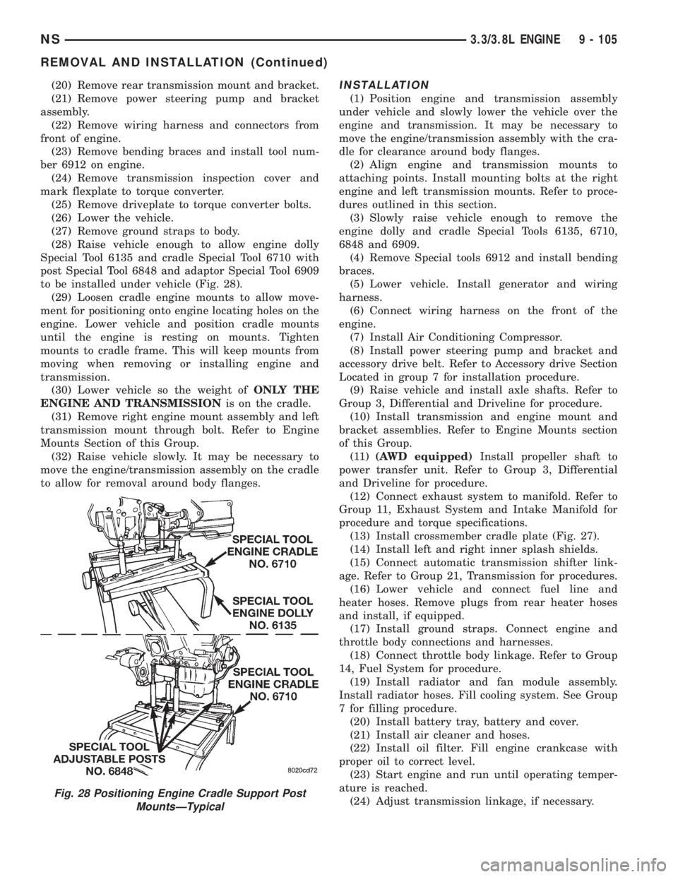
(28) Raise vehicle enough to allow engine dolly
Special Tool 6135 and cradle Special Tool 6710 with
post Special Tool 6848 and adaptor Special Tool 6909
to be installed under vehicle (Fig. 28).
(29) Loosen cradle engine mounts to allow move-
ment for positioning onto engine locating holes on the
engine. Lower vehicle and position cradle mounts
until the engine is resting on mounts. Tighten
mounts to cradle frame. This will keep mounts from
moving when removing or installing engine and
transmission.
(30) Lower vehicle so the weight ofONLY THE
ENGINE AND TRANSMISSIONis on the cradle.
(31) Remove right engine mount assembly and left
transmission mount through bolt. Refer to Engine
Mounts Section of this Group.
(32) Raise vehicle slowly. It may be necessary to
move the engine/transmission assembly on the cradle
to allow for removal around body flanges.INSTALLATION
(1) Position engine and transmission assembly
under vehicle and slowly lower the vehicle over the
engine and transmission. It may be necessary to
move the engine/transmission assembly with the cra-
dle for clearance around body flanges.
(2) Align engine and transmission mounts to
attaching points. Install mounting bolts at the right
engine and left transmission mounts. Refer to proce-
dures outlined in this section.
(3) Slowly raise vehicle enough to remove the
engine dolly and cradle Special Tools 6135, 6710,
6848 and 6909.
(4) Remove Special tools 6912 and install bending
braces.
(5) Lower vehicle. Install generator and wiring
harness.
(6) Connect wiring harness on the front of the
engine.
(7) Install Air Conditioning Compressor.
(8) Install power steering pump and bracket and
accessory drive belt. Refer to Accessory drive Section
Located in group 7 for installation procedure.
(9) Raise vehicle and install axle shafts. Refer to
Group 3, Differential and Driveline for procedure.
(10) Install transmission and engine mount and
bracket assemblies. Refer to Engine Mounts section
of this Group.
(11)(AWD equipped)Install propeller shaft to
power transfer unit. Refer to Group 3, Differential
and Driveline for procedure.
(12) Connect exhaust system to manifold. Refer to
Group 11, Exhaust System and Intake Manifold for
procedure and torque specifications.
(13) Install crossmember cradle plate (Fig. 27).
(14) Install left and right inner splash shields.
(15) Connect automatic transmission shifter link-
age. Refer to Group 21, Transmission for procedures.
(16) Lower vehicle and connect fuel line and
heater hoses. Remove plugs from rear heater hoses
and install, if equipped.
(17) Install ground straps. Connect engine and
throttle body connections and harnesses.
(18) Connect throttle body linkage. Refer to Group
14, Fuel System for procedure.
(19) Install radiator and fan module assembly.
Install radiator hoses. Fill cooling system. See Group
7 for filling procedure.
(20) Install battery tray, battery and cover.
(21) Install air cleaner and hoses.
(22) Install oil filter. Fill engine crankcase with
proper oil to correct level.
(23) Start engine and run until operating temper-
ature is reached.
(24) Adjust transmission linkage, if necessary.
Fig. 28 Positioning Engine Cradle Support Post
MountsÐTypical
NS3.3/3.8L ENGINE 9 - 105
REMOVAL AND INSTALLATION (Continued)
Page 1188 of 1938
HYDRAULIC LASH ADJUSTER NOISE
A tappet-like noise may be produced from several
items. Refer to Lash Adjuster Noise - Diagnosis in
Standard Service Procedures, outlined in this Group.
Lash adjusters are replaced with the rocker
arm as an assembly.
VALVE SEALS AND SPRINGS IN VEHICLE
REMOVAL
(1) Remove rocker arm shafts assemblies as previ-
ously outlined in this section.
(2) Rotate crankshaft until piston is at TDC on
compression.
(3) With air hose attached to adapter tool installed
in spark plug hole, apply 90-120 psi air pressure.
(4) Using Special Tool MD-998772A with adapter
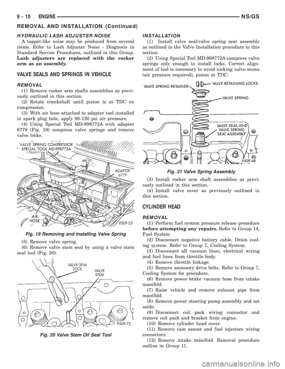
6779 (Fig. 19) compress valve springs and remove
valve locks.
(5) Remove valve spring.
(6) Remove valve stem seal by using a valve stem
seal tool (Fig. 20).
INSTALLATION
(1) Install valve seal/valve spring seat assembly
as outlined in the Valve Installation procedure in this
section.
(2) Using Special Tool MD-998772A compress valve
springs only enough to install locks. Correct align-
ment of tool is necessary to avoid nicking valve stems
(air pressure required), piston at TDC.
(3) Install rocker arm shaft assemblies as previ-
ously outlined in this section.
(4) Install valve cover as previously outlined in
this section.
CYLINDER HEAD
REMOVAL
(1) Perform fuel system pressure release procedure
before attempting any repairs.Refer to Group 14,
Fuel System
(2) Disconnect negative battery cable. Drain cool-
ing system. Refer to Group 7, Cooling System.
(3) Disconnect all vacuum lines, electrical wiring
and fuel lines from throttle body.
(4) Remove throttle linkage.
(5) Remove accessory drive belts. Refer to Group 7,
Cooling System for procedure.
(6) Remove power brake vacuum hose from intake
manifold.
(7) Raise vehicle and remove exhaust pipe from
manifold.
(8) Remove power steering pump assembly and set
aside.
(9) Disconnect coil pack wiring connector and
remove coil pack and bracket from engine.
(10) Remove cylinder head cover.
(11) Remove cam sensor and fuel injectors wiring
connectors.
(12) Remove intake manifold. Removal procedure
outline in Group 11.
Fig. 19 Removing and Installing Valve Spring
Fig. 20 Valve Stem Oil Seal Tool
Fig. 21 Valve Spring Assembly
9 - 10 ENGINENS/GS
REMOVAL AND INSTALLATION (Continued)
Page 1218 of 1938
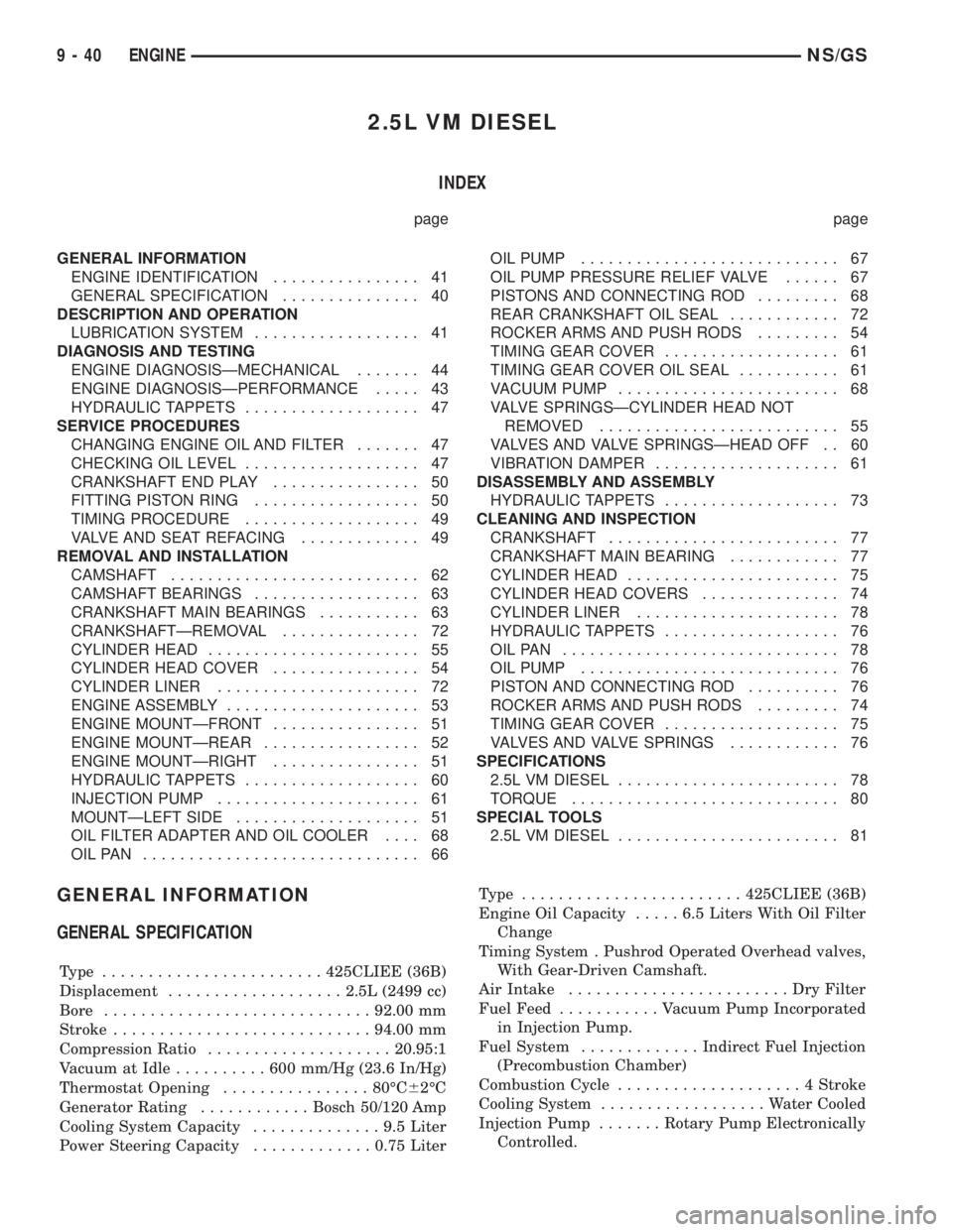
2.5L VM DIESEL
INDEX
page page
GENERAL INFORMATION
ENGINE IDENTIFICATION................ 41
GENERAL SPECIFICATION............... 40
DESCRIPTION AND OPERATION
LUBRICATION SYSTEM.................. 41
DIAGNOSIS AND TESTING
ENGINE DIAGNOSISÐMECHANICAL....... 44
ENGINE DIAGNOSISÐPERFORMANCE..... 43
HYDRAULIC TAPPETS................... 47
SERVICE PROCEDURES
CHANGING ENGINE OIL AND FILTER....... 47
CHECKING OIL LEVEL................... 47
CRANKSHAFT END PLAY................ 50
FITTING PISTON RING.................. 50
TIMING PROCEDURE................... 49
VALVE AND SEAT REFACING............. 49
REMOVAL AND INSTALLATION
CAMSHAFT........................... 62
CAMSHAFT BEARINGS.................. 63
CRANKSHAFT MAIN BEARINGS........... 63
CRANKSHAFTÐREMOVAL............... 72
CYLINDER HEAD....................... 55
CYLINDER HEAD COVER................ 54
CYLINDER LINER...................... 72
ENGINE ASSEMBLY..................... 53
ENGINE MOUNTÐFRONT................ 51
ENGINE MOUNTÐREAR................. 52
ENGINE MOUNTÐRIGHT................ 51
HYDRAULIC TAPPETS................... 60
INJECTION PUMP...................... 61
MOUNTÐLEFT SIDE.................... 51
OIL FILTER ADAPTER AND OIL COOLER.... 68
OILPAN .............................. 66OIL PUMP............................ 67
OIL PUMP PRESSURE RELIEF VALVE...... 67
PISTONS AND CONNECTING ROD......... 68
REAR CRANKSHAFT OIL SEAL............ 72
ROCKER ARMS AND PUSH RODS......... 54
TIMING GEAR COVER................... 61
TIMING GEAR COVER OIL SEAL........... 61
VACUUM PUMP........................ 68
VALVE SPRINGSÐCYLINDER HEAD NOT
REMOVED.......................... 55
VALVES AND VALVE SPRINGSÐHEAD OFF . . 60
VIBRATION DAMPER.................... 61
DISASSEMBLY AND ASSEMBLY
HYDRAULIC TAPPETS................... 73
CLEANING AND INSPECTION
CRANKSHAFT......................... 77
CRANKSHAFT MAIN BEARING............ 77
CYLINDER HEAD....................... 75
CYLINDER HEAD COVERS............... 74
CYLINDER LINER...................... 78
HYDRAULIC TAPPETS................... 76
OILPAN .............................. 78
OIL PUMP............................ 76
PISTON AND CONNECTING ROD.......... 76
ROCKER ARMS AND PUSH RODS......... 74
TIMING GEAR COVER................... 75
VALVES AND VALVE SPRINGS............ 76
SPECIFICATIONS
2.5L VM DIESEL........................ 78
TORQUE............................. 80
SPECIAL TOOLS
2.5L VM DIESEL........................ 81
GENERAL INFORMATION
GENERAL SPECIFICATION
Type ........................425CLIEE (36B)
Displacement...................2.5L (2499 cc)
Bore.............................92.00 mm
Stroke............................94.00 mm
Compression Ratio....................20.95:1
Vacuum at Idle..........600mm/Hg (23.6 In/Hg)
Thermostat Opening................80ÉC62ÉC
Generator Rating............Bosch 50/120 Amp
Cooling System Capacity..............9.5Liter
Power Steering Capacity.............0.75 LiterType ........................425CLIEE (36B)
Engine Oil Capacity.....6.5Liters With Oil Filter
Change
Timing System . Pushrod Operated Overhead valves,
With Gear-Driven Camshaft.
Air Intake........................DryFilter
Fuel Feed...........Vacuum Pump Incorporated
in Injection Pump.
Fuel System.............Indirect Fuel Injection
(Precombustion Chamber)
Combustion Cycle....................4Stroke
Cooling System..................Water Cooled
Injection Pump.......Rotary Pump Electronically
Controlled.
9 - 40 ENGINENS/GS
Page 1221 of 1938
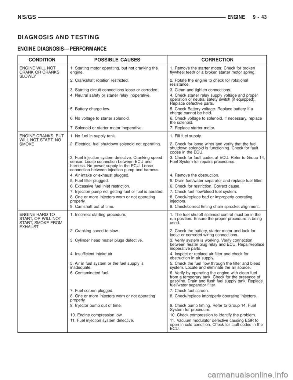
DIAGNOSIS AND TESTING
ENGINE DIAGNOSISÐPERFORMANCE
CONDITION POSSIBLE CAUSES CORRECTION
ENGINE WILL NOT
CRANK OR CRANKS
SLOWLY1. Starting motor operating, but not cranking the
engine.1. Remove the starter motor. Check for broken
flywheel teeth or a broken starter motor spring.
2. Crankshaft rotation restricted. 2. Rotate the engine to check for rotational
resistance.
3. Starting circuit connections loose or corroded. 3. Clean and tighten connections.
4. Neutral safety or starter relay inoperative. 4. Check starter relay supply voltage and proper
operation of neutral safety switch (if equipped).
Replace defective parts.
5. Battery charge low. 5. Check Battery voltage. Replace battery if a
charge cannot be held.
6. No voltage to starter solenoid. 6. Check voltage to solenoid. If necessary, replace
the solenoid.
7. Solenoid or starter motor inoperative. 7. Replace starter motor.
ENGINE CRANKS, BUT
WILL NOT START, NO
SMOKE1. No fuel in supply tank. 1. Fill fuel supply.
2. Electrical fuel shutdown solenoid not operating. 2. Check for loose wires and verify that the fuel
shutdown solenoid is functioning. Check for fault
codes in the ECU.
3. Fuel injection system defective: Cranking speed
sensor. Loose connection between ECU and
harness. No power supply to the ECU. Loose
connection between injection pump and harness.3. Check for fault codes at ECU. Refer to Group 14,
Fuel System for repairs procedures.
4. Air intake or exhaust plugged. 4. Remove the obstruction.
5. Fuel filter plugged. 5. Drain fuel/water separator and replace fuel filter.
6. Excessive fuel inlet restriction. 6. Check for restriction. Correct cause.
7. Injection pump not getting fuel or fuel is aerated. 7. Check fuel flow/bleed fuel system.
8. One or more injectors worn or not operating
properly.8. Check/replace bad or improperly operating
injectors.
9. Camshaft out of time. 9. Check/correct timing chain sprocket alignment.
ENGINE HARD TO
START, OR WILL NOT
START, SMOKE FROM
EXHAUST1. Incorrect starting procedure. 1. The fuel shutoff solenoid control must be in the
run position. Ensure the proper procedure is being
used.
2. Cranking speed to slow. 2. Check the battery, starter motor and look for
loose or corroded wiring connections.
3. Cylinder head heater plugs defective. 3. Verify system is working. Verify connection
between heater plug relay and ECU. Repair/replace
inoperative parts.
4. Insufficient intake air 4. Inspect or replace air filter and check for
obstruction in air supply.
5. Air in fuel system or the fuel supply is
inadequate.5. Check the fuel flow through the filter and bleed
system. Locate and eliminate the air source.
6. Contaminated fuel. 6. Verify by operating the engine with clean fuel
from a temporary tank. Check for the presence of
gasoline. Drain and flush fuel supply tank. Replace
fuel/water separator filter.
7. Fuel screen plugged. 7. Check fuel screen.
8. One or more injectors worn or not operating
properly.8. Check/replace improperly operating injectors.
9. Injector pump out of time. 9. Check pump timing. Refer to Group 14, Fuel
System for procedure.
10. Engine compression low. 10. Check compression to identify the problem.
11. Fuel injection system defective. 11. Vacuum modulator defective causing EGR to
open in cold condition. Check for fault codes in the
ECU.
NS/GSENGINE 9 - 43
Page 1222 of 1938
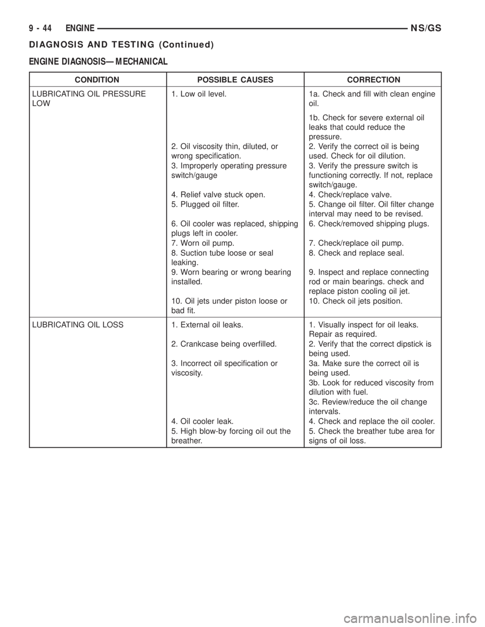
ENGINE DIAGNOSISÐMECHANICAL
CONDITION POSSIBLE CAUSES CORRECTION
LUBRICATING OIL PRESSURE
LOW1. Low oil level. 1a. Check and fill with clean engine
oil.
1b. Check for severe external oil
leaks that could reduce the
pressure.
2. Oil viscosity thin, diluted, or
wrong specification.2. Verify the correct oil is being
used. Check for oil dilution.
3. Improperly operating pressure
switch/gauge3. Verify the pressure switch is
functioning correctly. If not, replace
switch/gauge.
4. Relief valve stuck open. 4. Check/replace valve.
5. Plugged oil filter. 5. Change oil filter. Oil filter change
interval may need to be revised.
6. Oil cooler was replaced, shipping
plugs left in cooler.6. Check/removed shipping plugs.
7. Worn oil pump. 7. Check/replace oil pump.
8. Suction tube loose or seal
leaking.8. Check and replace seal.
9. Worn bearing or wrong bearing
installed.9. Inspect and replace connecting
rod or main bearings. check and
replace piston cooling oil jet.
10. Oil jets under piston loose or
bad fit.10. Check oil jets position.
LUBRICATING OIL LOSS 1. External oil leaks. 1. Visually inspect for oil leaks.
Repair as required.
2. Crankcase being overfilled. 2. Verify that the correct dipstick is
being used.
3. Incorrect oil specification or
viscosity.3a. Make sure the correct oil is
being used.
3b. Look for reduced viscosity from
dilution with fuel.
3c. Review/reduce the oil change
intervals.
4. Oil cooler leak. 4. Check and replace the oil cooler.
5. High blow-by forcing oil out the
breather.5. Check the breather tube area for
signs of oil loss.
9 - 44 ENGINENS/GS
DIAGNOSIS AND TESTING (Continued)
Page 1223 of 1938
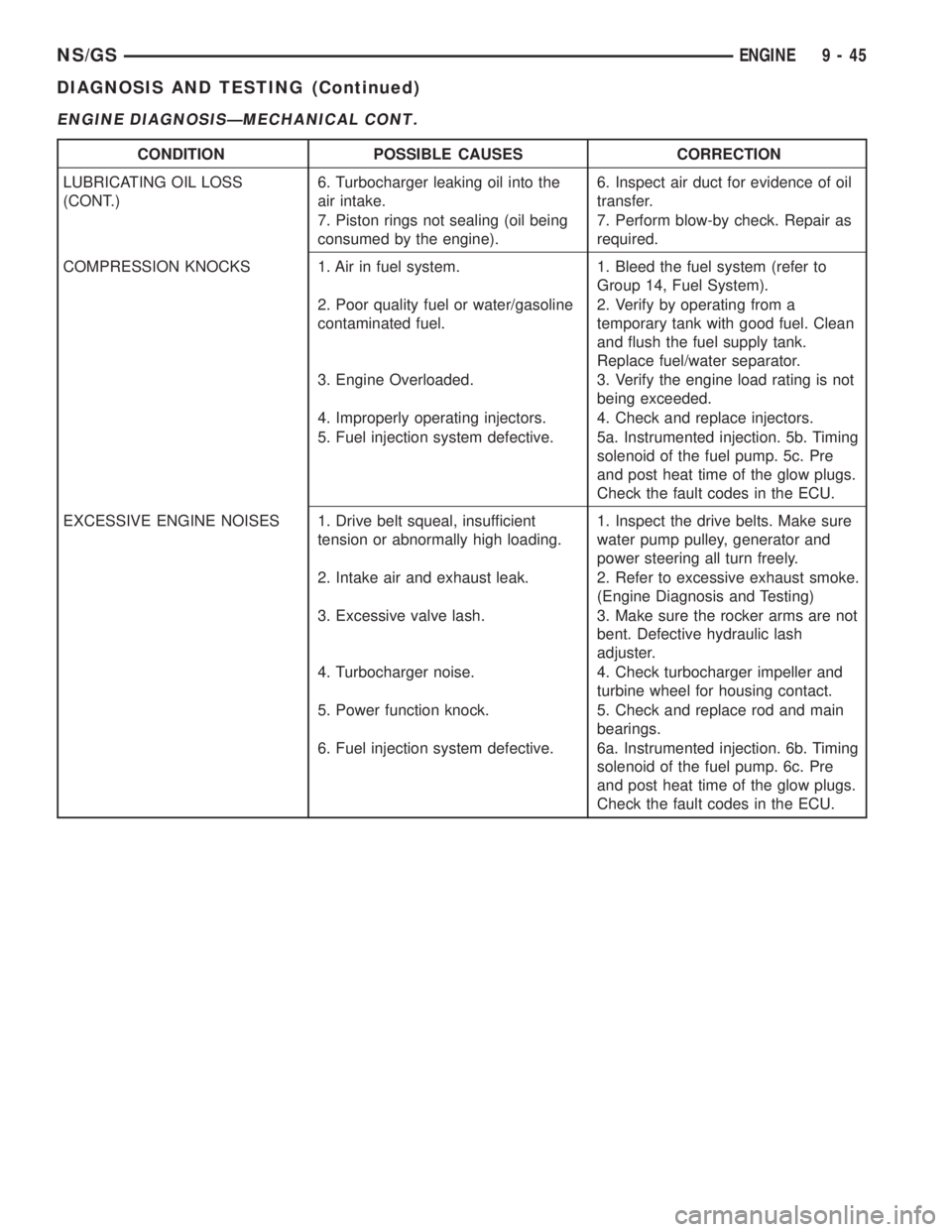
ENGINE DIAGNOSISÐMECHANICAL CONT.
CONDITION POSSIBLE CAUSES CORRECTION
LUBRICATING OIL LOSS
(CONT.)6. Turbocharger leaking oil into the
air intake.6. Inspect air duct for evidence of oil
transfer.
7. Piston rings not sealing (oil being
consumed by the engine).7. Perform blow-by check. Repair as
required.
COMPRESSION KNOCKS 1. Air in fuel system. 1. Bleed the fuel system (refer to
Group 14, Fuel System).
2. Poor quality fuel or water/gasoline
contaminated fuel.2. Verify by operating from a
temporary tank with good fuel. Clean
and flush the fuel supply tank.
Replace fuel/water separator.
3. Engine Overloaded. 3. Verify the engine load rating is not
being exceeded.
4. Improperly operating injectors. 4. Check and replace injectors.
5. Fuel injection system defective. 5a. Instrumented injection. 5b. Timing
solenoid of the fuel pump. 5c. Pre
and post heat time of the glow plugs.
Check the fault codes in the ECU.
EXCESSIVE ENGINE NOISES 1. Drive belt squeal, insufficient
tension or abnormally high loading.1. Inspect the drive belts. Make sure
water pump pulley, generator and
power steering all turn freely.
2. Intake air and exhaust leak. 2. Refer to excessive exhaust smoke.
(Engine Diagnosis and Testing)
3. Excessive valve lash. 3. Make sure the rocker arms are not
bent. Defective hydraulic lash
adjuster.
4. Turbocharger noise. 4. Check turbocharger impeller and
turbine wheel for housing contact.
5. Power function knock. 5. Check and replace rod and main
bearings.
6. Fuel injection system defective. 6a. Instrumented injection. 6b. Timing
solenoid of the fuel pump. 6c. Pre
and post heat time of the glow plugs.
Check the fault codes in the ECU.
NS/GSENGINE 9 - 45
DIAGNOSIS AND TESTING (Continued)