1996 CHRYSLER VOYAGER wheel alignment
[x] Cancel search: wheel alignmentPage 1460 of 1938
ASSEMBLE
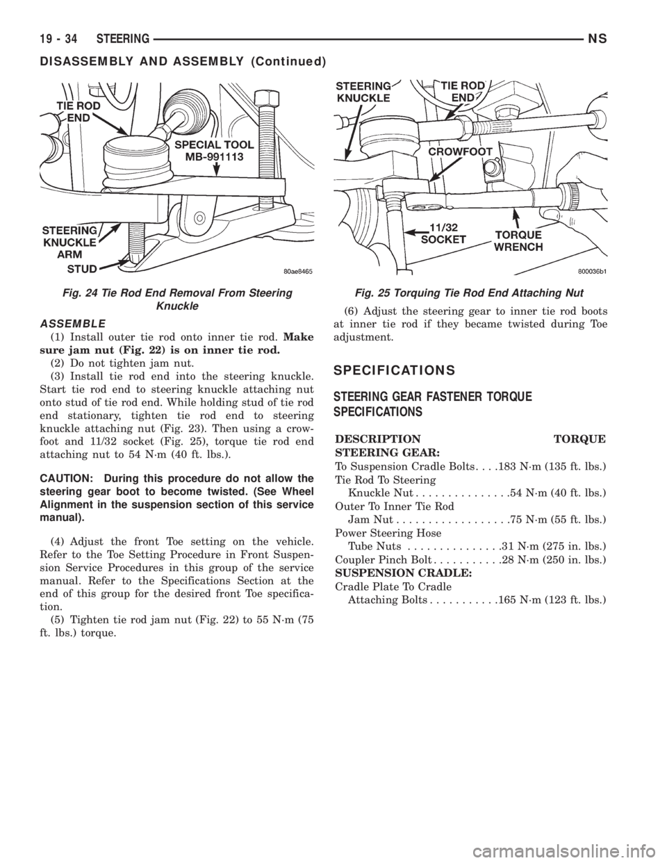
(1) Install outer tie rod onto inner tie rod.Make
sure jam nut (Fig. 22) is on inner tie rod.
(2) Do not tighten jam nut.
(3) Install tie rod end into the steering knuckle.
Start tie rod end to steering knuckle attaching nut
onto stud of tie rod end. While holding stud of tie rod
end stationary, tighten tie rod end to steering
knuckle attaching nut (Fig. 23). Then using a crow-
foot and 11/32 socket (Fig. 25), torque tie rod end
attaching nut to 54 N´m (40 ft. lbs.).
CAUTION: During this procedure do not allow the
steering gear boot to become twisted. (See Wheel
Alignment in the suspension section of this service
manual).
(4) Adjust the front Toe setting on the vehicle.
Refer to the Toe Setting Procedure in Front Suspen-
sion Service Procedures in this group of the service
manual. Refer to the Specifications Section at the
end of this group for the desired front Toe specifica-
tion.
(5) Tighten tie rod jam nut (Fig. 22) to 55 N´m (75
ft. lbs.) torque.(6) Adjust the steering gear to inner tie rod boots
at inner tie rod if they became twisted during Toe
adjustment.
SPECIFICATIONS
STEERING GEAR FASTENER TORQUE
SPECIFICATIONS
DESCRIPTION TORQUE
STEERING GEAR:
To Suspension Cradle Bolts. . . .183 N´m (135 ft. lbs.)
Tie Rod To Steering
Knuckle Nut...............54N´m(40ft.lbs.)
Outer To Inner Tie Rod
JamNut..................75N´m(55ft.lbs.)
Power Steering Hose
Tube Nuts...............31N´m(275 in. lbs.)
Coupler Pinch Bolt...........28N´m(250 in. lbs.)
SUSPENSION CRADLE:
Cradle Plate To Cradle
Attaching Bolts...........165 N´m (123 ft. lbs.)
Fig. 24 Tie Rod End Removal From Steering
KnuckleFig. 25 Torquing Tie Rod End Attaching Nut
19 - 34 STEERINGNS
DISASSEMBLY AND ASSEMBLY (Continued)
Page 1727 of 1938
WHEELS
INDEX
page page
DESCRIPTION AND OPERATION
WHEEL INFORMATION.................... 9
DIAGNOSIS AND TESTING
TIRE AND WHEEL RUNOUT............... 10
WHEEL INSPECTION...................... 9SERVICE PROCEDURES
TIRE AND WHEEL BALANCE............... 11
WHEEL INSTALLATION................... 11
SPECIFICATIONS
WHEEL SPECIFICATIONS................. 12
DESCRIPTION AND OPERATION
WHEEL INFORMATION
Original equipment wheels are designed for proper
operation at all loads up to the specified maximum
vehicle capacity.
All models use steel or aluminum drop center
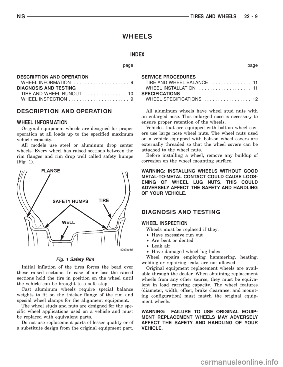
wheels. Every wheel has raised sections between the
rim flanges and rim drop well called safety humps
(Fig. 1).
Initial inflation of the tires forces the bead over
these raised sections. In case of air loss the raised
sections hold the tire in position on the wheel until
the vehicle can be brought to a safe stop.
Cast aluminum wheels require special balance
weights to fit on the thicker flange of the rim and
special wheel clamps for the alignment equipment.
The wheel studs and nuts are designed for the spe-
cific wheel applications used on a vehicle and must
be replaced with equivalent parts.
Do not use replacement parts of lesser quality or of
a substitute design from the original equipment part.All aluminum wheels have wheel stud nuts with
an enlarged nose. This enlarged nose is necessary to
ensure proper retention of the wheels.
Vehicles that are equipped with bolt-on wheel cov-
ers use large nose wheel nuts. The wheel nuts used
on a vehicle equipped with bolt-on wheel covers are
externally threaded so that the wheel covers can be
attached to the wheel nuts.
Before installing a wheel, remove any buildup of
corrosion on the wheel mounting surface.
WARNING: INSTALLING WHEELS WITHOUT GOOD
METAL-TO-METAL CONTACT COULD CAUSE LOOS-
ENING OF WHEEL LUG NUTS. THIS COULD
ADVERSELY AFFECT THE SAFETY AND HANDLING
OF YOUR VEHICLE.
DIAGNOSIS AND TESTING
WHEEL INSPECTION
Wheels must be replaced if they:
²Have excessive run out
²Are bent or dented
²Leak air
²Have damaged wheel lug holes
Wheel repairs employing hammering, heating,
welding or repairing leaks are not allowed.
Original equipment replacement wheels are avail-
able through the dealer. When obtaining replacement
wheels from any other source, they must be equiva-
lent in load carrying capacity. The wheel features
(diameter, width, offset, brake clearance, and mount-
ing configuration) must match the original equip-
ment wheels.
WARNING: FAILURE TO USE ORIGINAL EQUIP-
MENT REPLACEMENT WHEELS MAY ADVERSELY
AFFECT THE SAFETY AND HANDLING OF YOUR
VEHICLE.
Fig. 1 Safety Rim
NSTIRES AND WHEELS 22 - 9
Page 1758 of 1938
(6) Connect door harness into body wiring harness.
(7) Connect positive lock slide on the side of the
wire connectors.
(8) Connect clips to hold door harness wire connec-
tor to inner fender brace.
(9) Install front wheelhouse splash shield.
(10) Verify door operation and alignment. Adjust
as necessary.
FRONT DOOR APPLIQUE
REMOVAL
(1) Roll door glass down.
(2) Remove outer door belt molding.
(3) Disengage clips holding front edge of applique
to door frame.
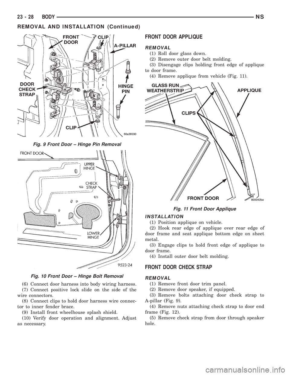
(4) Remove applique from vehicle (Fig. 11).
INSTALLATION
(1) Position applique on vehicle.
(2) Hook rear edge of applique over rear edge of
door frame and seat applique bottom edge on sheet
metal.
(3) Engage clips to hold front edge of applique to
door frame.
(4) Install outer door belt molding.
FRONT DOOR CHECK STRAP
REMOVAL
(1) Remove front door trim panel.
(2) Remove door speaker, if equipped.
(3) Remove bolts attaching door check strap to
A-pillar (Fig. 9).
(4) Remove nuts attaching check strap to door end
frame (Fig. 12).
(5) Remove check strap from door through speaker
hole.
Fig. 9 Front Door ± Hinge Pin Removal
Fig. 10 Front Door ± Hinge Bolt Removal
Fig. 11 Front Door Applique
23 - 28 BODYNS
REMOVAL AND INSTALLATION (Continued)
Page 1767 of 1938
INSTALLATION
(1) Insert front guide rail through front access
hole.
(2) Insert rear guide rail through rear access hole.
(3) Place window regulator in position on inner
door panel.
(4) Place screw heads on guide rails in position
through key hole slots in inner door panel.
(5) Tighten screws to attach front and rear guide
rails to inner door panel.
(6) Connect wire connector into power window
motor, if equipped.
(7) Install door glass.
(8) Verify door glass alignment and operation.
(9) Install water shield and door trim panel.
FRONT SEAT
REMOVAL
(1) From under vehicle, remove nuts attaching
front seat risers to the floor.
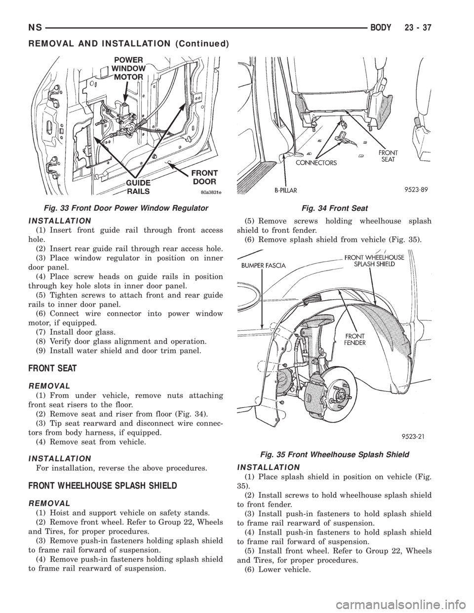
(2) Remove seat and riser from floor (Fig. 34).
(3) Tip seat rearward and disconnect wire connec-
tors from body harness, if equipped.
(4) Remove seat from vehicle.
INSTALLATION
For installation, reverse the above procedures.
FRONT WHEELHOUSE SPLASH SHIELD
REMOVAL
(1) Hoist and support vehicle on safety stands.
(2) Remove front wheel. Refer to Group 22, Wheels
and Tires, for proper procedures.
(3) Remove push-in fasteners holding splash shield
to frame rail forward of suspension.
(4) Remove push-in fasteners holding splash shield
to frame rail rearward of suspension.(5) Remove screws holding wheelhouse splash
shield to front fender.
(6) Remove splash shield from vehicle (Fig. 35).
INSTALLATION
(1) Place splash shield in position on vehicle (Fig.
35).
(2) Install screws to hold wheelhouse splash shield
to front fender.
(3) Install push-in fasteners to hold splash shield
to frame rail rearward of suspension.
(4) Install push-in fasteners to hold splash shield
to frame rail forward of suspension.
(5) Install front wheel. Refer to Group 22, Wheels
and Tires, for proper procedures.
(6) Lower vehicle.
Fig. 33 Front Door Power Window RegulatorFig. 34 Front Seat
Fig. 35 Front Wheelhouse Splash Shield
NSBODY 23 - 37
REMOVAL AND INSTALLATION (Continued)
Page 1805 of 1938
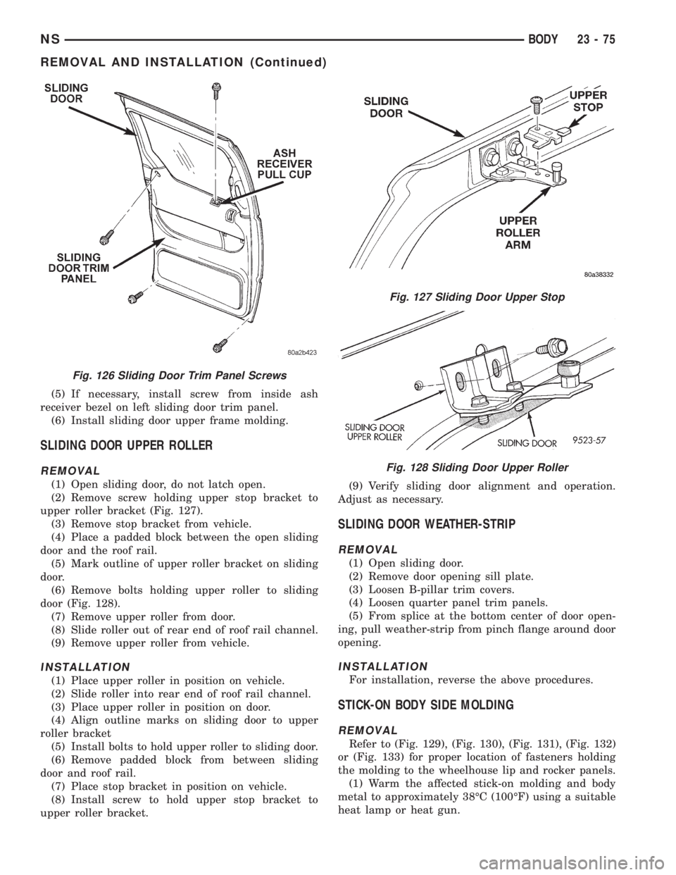
(5) If necessary, install screw from inside ash
receiver bezel on left sliding door trim panel.
(6) Install sliding door upper frame molding.
SLIDING DOOR UPPER ROLLER
REMOVAL
(1) Open sliding door, do not latch open.
(2) Remove screw holding upper stop bracket to
upper roller bracket (Fig. 127).
(3) Remove stop bracket from vehicle.
(4) Place a padded block between the open sliding
door and the roof rail.
(5) Mark outline of upper roller bracket on sliding
door.
(6) Remove bolts holding upper roller to sliding
door (Fig. 128).
(7) Remove upper roller from door.
(8) Slide roller out of rear end of roof rail channel.
(9) Remove upper roller from vehicle.
INSTALLATION
(1) Place upper roller in position on vehicle.
(2) Slide roller into rear end of roof rail channel.
(3) Place upper roller in position on door.
(4) Align outline marks on sliding door to upper
roller bracket
(5) Install bolts to hold upper roller to sliding door.
(6) Remove padded block from between sliding
door and roof rail.
(7) Place stop bracket in position on vehicle.
(8) Install screw to hold upper stop bracket to
upper roller bracket.(9) Verify sliding door alignment and operation.
Adjust as necessary.
SLIDING DOOR WEATHER-STRIP
REMOVAL
(1) Open sliding door.
(2) Remove door opening sill plate.
(3) Loosen B-pillar trim covers.
(4) Loosen quarter panel trim panels.
(5) From splice at the bottom center of door open-
ing, pull weather-strip from pinch flange around door
opening.
INSTALLATION
For installation, reverse the above procedures.
STICK-ON BODY SIDE MOLDING
REMOVAL
Refer to (Fig. 129), (Fig. 130), (Fig. 131), (Fig. 132)
or (Fig. 133) for proper location of fasteners holding
the molding to the wheelhouse lip and rocker panels.
(1) Warm the affected stick-on molding and body
metal to approximately 38ÉC (100ÉF) using a suitable
heat lamp or heat gun.
Fig. 126 Sliding Door Trim Panel Screws
Fig. 127 Sliding Door Upper Stop
Fig. 128 Sliding Door Upper Roller
NSBODY 23 - 75
REMOVAL AND INSTALLATION (Continued)
Page 1856 of 1938
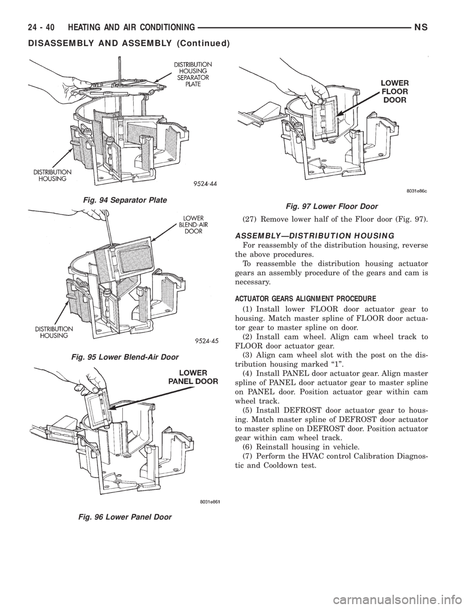
(27) Remove lower half of the Floor door (Fig. 97).
ASSEMBLYÐDISTRIBUTION HOUSING
For reassembly of the distribution housing, reverse
the above procedures.
To reassemble the distribution housing actuator
gears an assembly procedure of the gears and cam is
necessary.
ACTUATOR GEARS ALIGNMENT PROCEDURE
(1) Install lower FLOOR door actuator gear to
housing. Match master spline of FLOOR door actua-
tor gear to master spline on door.
(2) Install cam wheel. Align cam wheel track to
FLOOR door actuator gear.
(3) Align cam wheel slot with the post on the dis-
tribution housing marked ª1º.
(4) Install PANEL door actuator gear. Align master
spline of PANEL door actuator gear to master spline
on PANEL door. Position actuator gear within cam
wheel track.
(5) Install DEFROST door actuator gear to hous-
ing. Match master spline of DEFROST door actuator
to master spline on DEFROST door. Position actuator
gear within cam wheel track.
(6) Reinstall housing in vehicle.
(7) Perform the HVAC control Calibration Diagnos-
tic and Cooldown test.
Fig. 97 Lower Floor DoorFig. 94 Separator Plate
Fig. 95 Lower Blend-Air Door
Fig. 96 Lower Panel Door
24 - 40 HEATING AND AIR CONDITIONINGNS
DISASSEMBLY AND ASSEMBLY (Continued)
Page 1902 of 1938
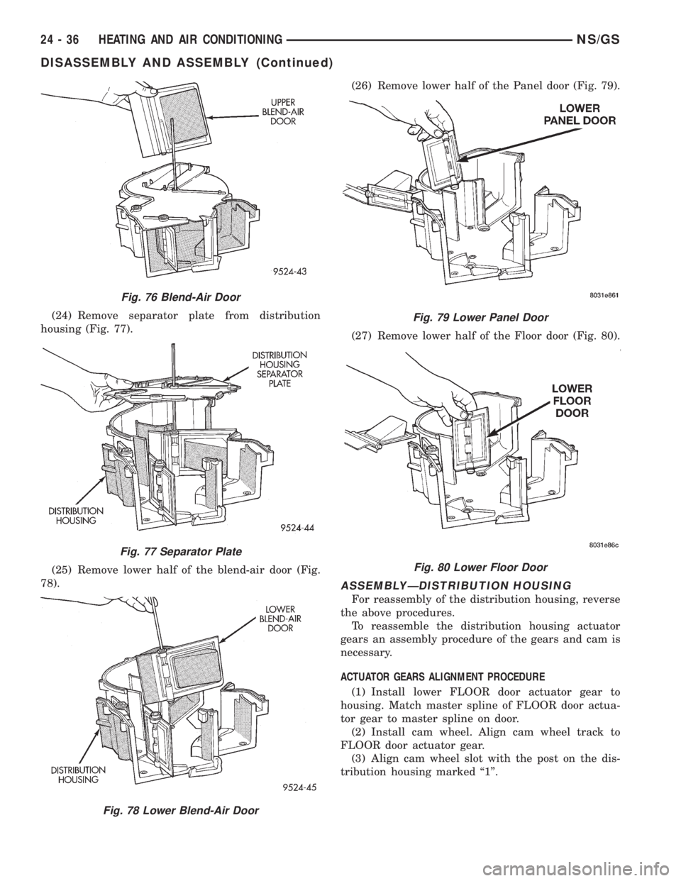
(24) Remove separator plate from distribution
housing (Fig. 77).
(25) Remove lower half of the blend-air door (Fig.
78).(26) Remove lower half of the Panel door (Fig. 79).
(27) Remove lower half of the Floor door (Fig. 80).
ASSEMBLYÐDISTRIBUTION HOUSING
For reassembly of the distribution housing, reverse
the above procedures.
To reassemble the distribution housing actuator
gears an assembly procedure of the gears and cam is
necessary.
ACTUATOR GEARS ALIGNMENT PROCEDURE
(1) Install lower FLOOR door actuator gear to
housing. Match master spline of FLOOR door actua-
tor gear to master spline on door.
(2) Install cam wheel. Align cam wheel track to
FLOOR door actuator gear.
(3) Align cam wheel slot with the post on the dis-
tribution housing marked ª1º.
Fig. 76 Blend-Air Door
Fig. 77 Separator Plate
Fig. 78 Lower Blend-Air Door
Fig. 79 Lower Panel Door
Fig. 80 Lower Floor Door
24 - 36 HEATING AND AIR CONDITIONINGNS/GS
DISASSEMBLY AND ASSEMBLY (Continued)