1996 CHRYSLER VOYAGER wheel alignment
[x] Cancel search: wheel alignmentPage 1181 of 1938
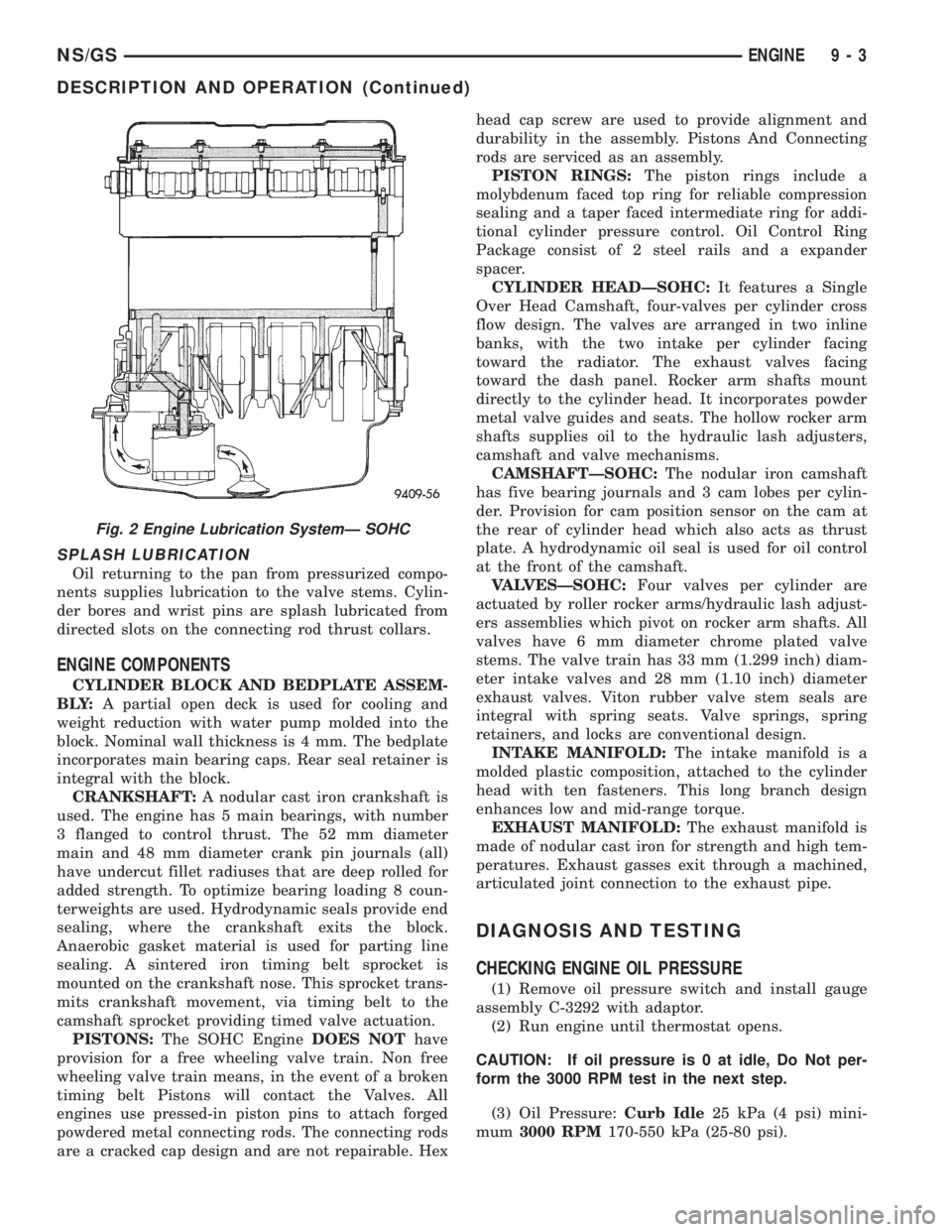
SPLASH LUBRICATION
Oil returning to the pan from pressurized compo-
nents supplies lubrication to the valve stems. Cylin-
der bores and wrist pins are splash lubricated from
directed slots on the connecting rod thrust collars.
ENGINE COMPONENTS
CYLINDER BLOCK AND BEDPLATE ASSEM-
B LY:A partial open deck is used for cooling and
weight reduction with water pump molded into the
block. Nominal wall thickness is 4 mm. The bedplate
incorporates main bearing caps. Rear seal retainer is
integral with the block.
CRANKSHAFT:A nodular cast iron crankshaft is
used. The engine has 5 main bearings, with number
3 flanged to control thrust. The 52 mm diameter
main and 48 mm diameter crank pin journals (all)
have undercut fillet radiuses that are deep rolled for
added strength. To optimize bearing loading 8 coun-
terweights are used. Hydrodynamic seals provide end
sealing, where the crankshaft exits the block.
Anaerobic gasket material is used for parting line
sealing. A sintered iron timing belt sprocket is
mounted on the crankshaft nose. This sprocket trans-
mits crankshaft movement, via timing belt to the
camshaft sprocket providing timed valve actuation.
PISTONS:The SOHC EngineDOES NOThave
provision for a free wheeling valve train. Non free
wheeling valve train means, in the event of a broken
timing belt Pistons will contact the Valves. All
engines use pressed-in piston pins to attach forged
powdered metal connecting rods. The connecting rods
are a cracked cap design and are not repairable. Hexhead cap screw are used to provide alignment and
durability in the assembly. Pistons And Connecting
rods are serviced as an assembly.
PISTON RINGS:The piston rings include a
molybdenum faced top ring for reliable compression
sealing and a taper faced intermediate ring for addi-
tional cylinder pressure control. Oil Control Ring
Package consist of 2 steel rails and a expander
spacer.
CYLINDER HEADÐSOHC:It features a Single
Over Head Camshaft, four-valves per cylinder cross
flow design. The valves are arranged in two inline
banks, with the two intake per cylinder facing
toward the radiator. The exhaust valves facing
toward the dash panel. Rocker arm shafts mount
directly to the cylinder head. It incorporates powder
metal valve guides and seats. The hollow rocker arm
shafts supplies oil to the hydraulic lash adjusters,
camshaft and valve mechanisms.
CAMSHAFTÐSOHC:The nodular iron camshaft
has five bearing journals and 3 cam lobes per cylin-
der. Provision for cam position sensor on the cam at
the rear of cylinder head which also acts as thrust
plate. A hydrodynamic oil seal is used for oil control
at the front of the camshaft.
VALVESÐSOHC:Four valves per cylinder are
actuated by roller rocker arms/hydraulic lash adjust-
ers assemblies which pivot on rocker arm shafts. All
valves have 6 mm diameter chrome plated valve
stems. The valve train has 33 mm (1.299 inch) diam-
eter intake valves and 28 mm (1.10 inch) diameter
exhaust valves. Viton rubber valve stem seals are
integral with spring seats. Valve springs, spring
retainers, and locks are conventional design.
INTAKE MANIFOLD:The intake manifold is a
molded plastic composition, attached to the cylinder
head with ten fasteners. This long branch design
enhances low and mid-range torque.
EXHAUST MANIFOLD:The exhaust manifold is
made of nodular cast iron for strength and high tem-
peratures. Exhaust gasses exit through a machined,
articulated joint connection to the exhaust pipe.
DIAGNOSIS AND TESTING
CHECKING ENGINE OIL PRESSURE
(1) Remove oil pressure switch and install gauge
assembly C-3292 with adaptor.
(2) Run engine until thermostat opens.
CAUTION: If oil pressure is 0 at idle, Do Not per-
form the 3000 RPM test in the next step.
(3) Oil Pressure:Curb Idle25 kPa (4 psi) mini-
mum3000 RPM170-550 kPa (25-80 psi).
Fig. 2 Engine Lubrication SystemÐ SOHC
NS/GSENGINE 9 - 3
DESCRIPTION AND OPERATION (Continued)
Page 1221 of 1938
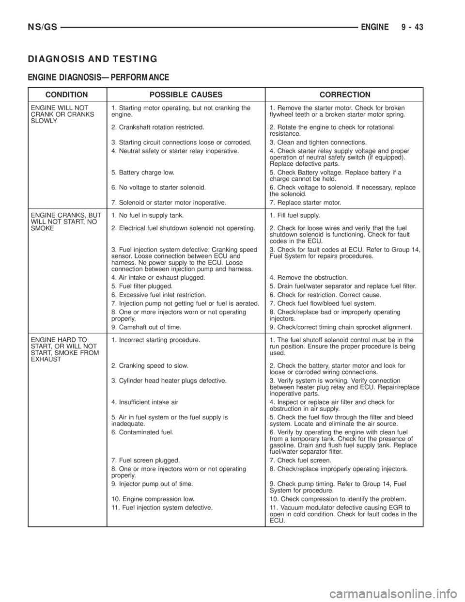
DIAGNOSIS AND TESTING
ENGINE DIAGNOSISÐPERFORMANCE
CONDITION POSSIBLE CAUSES CORRECTION
ENGINE WILL NOT
CRANK OR CRANKS
SLOWLY1. Starting motor operating, but not cranking the
engine.1. Remove the starter motor. Check for broken
flywheel teeth or a broken starter motor spring.
2. Crankshaft rotation restricted. 2. Rotate the engine to check for rotational
resistance.
3. Starting circuit connections loose or corroded. 3. Clean and tighten connections.
4. Neutral safety or starter relay inoperative. 4. Check starter relay supply voltage and proper
operation of neutral safety switch (if equipped).
Replace defective parts.
5. Battery charge low. 5. Check Battery voltage. Replace battery if a
charge cannot be held.
6. No voltage to starter solenoid. 6. Check voltage to solenoid. If necessary, replace
the solenoid.
7. Solenoid or starter motor inoperative. 7. Replace starter motor.
ENGINE CRANKS, BUT
WILL NOT START, NO
SMOKE1. No fuel in supply tank. 1. Fill fuel supply.
2. Electrical fuel shutdown solenoid not operating. 2. Check for loose wires and verify that the fuel
shutdown solenoid is functioning. Check for fault
codes in the ECU.
3. Fuel injection system defective: Cranking speed
sensor. Loose connection between ECU and
harness. No power supply to the ECU. Loose
connection between injection pump and harness.3. Check for fault codes at ECU. Refer to Group 14,
Fuel System for repairs procedures.
4. Air intake or exhaust plugged. 4. Remove the obstruction.
5. Fuel filter plugged. 5. Drain fuel/water separator and replace fuel filter.
6. Excessive fuel inlet restriction. 6. Check for restriction. Correct cause.
7. Injection pump not getting fuel or fuel is aerated. 7. Check fuel flow/bleed fuel system.
8. One or more injectors worn or not operating
properly.8. Check/replace bad or improperly operating
injectors.
9. Camshaft out of time. 9. Check/correct timing chain sprocket alignment.
ENGINE HARD TO
START, OR WILL NOT
START, SMOKE FROM
EXHAUST1. Incorrect starting procedure. 1. The fuel shutoff solenoid control must be in the
run position. Ensure the proper procedure is being
used.
2. Cranking speed to slow. 2. Check the battery, starter motor and look for
loose or corroded wiring connections.
3. Cylinder head heater plugs defective. 3. Verify system is working. Verify connection
between heater plug relay and ECU. Repair/replace
inoperative parts.
4. Insufficient intake air 4. Inspect or replace air filter and check for
obstruction in air supply.
5. Air in fuel system or the fuel supply is
inadequate.5. Check the fuel flow through the filter and bleed
system. Locate and eliminate the air source.
6. Contaminated fuel. 6. Verify by operating the engine with clean fuel
from a temporary tank. Check for the presence of
gasoline. Drain and flush fuel supply tank. Replace
fuel/water separator filter.
7. Fuel screen plugged. 7. Check fuel screen.
8. One or more injectors worn or not operating
properly.8. Check/replace improperly operating injectors.
9. Injector pump out of time. 9. Check pump timing. Refer to Group 14, Fuel
System for procedure.
10. Engine compression low. 10. Check compression to identify the problem.
11. Fuel injection system defective. 11. Vacuum modulator defective causing EGR to
open in cold condition. Check for fault codes in the
ECU.
NS/GSENGINE 9 - 43
Page 1283 of 1938
FRAME
INDEX
page page
REMOVAL AND INSTALLATION
FRONT CROSSMEMBER MOUNT BUSHINGS . . . 5
FRONT CROSSMEMBER................... 3SPECIFICATIONS
FRAME AND BODY OPENING DIMENSIONS.... 5
REMOVAL AND INSTALLATION
FRONT CROSSMEMBER
The front suspension crossmember must be
installed in the design location to achieve proper
front end suspension alignment. If the crossmember
is removed without applying reference marks on the
frame rails, align the crossmember according to the
dimensions provided in this group.
NOTE: If the caged nuts in the frame rails become
damaged and cannot be reused, a replacement nut
can be obtained through a MoparTParts supplier.
REMOVAL
(1) Disconnect battery negative cable.
(2) Remove steering column lower cover from
instrument panel. Refer to Group 8E, Instrument
Panel and Systems.
(3) Remove knee blocker reinforcement. Refer to
Group 8E, Instrument Panel and Systems.
(4) Position steering so front wheels are straight
ahead.
CAUTION: Do not rotate steering wheel after disen-
gaging lower coupling from steering gear, damage
to airbag clock spring can result.
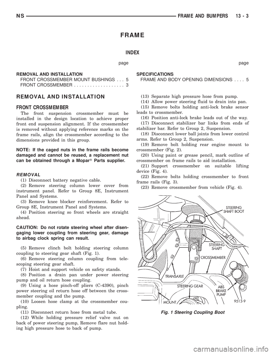
(5) Remove clinch bolt holding steering column
coupling to steering gear shaft (Fig. 1).
(6) Remove steering column coupling from tele-
scoping steering gear shaft.
(7) Hoist and support vehicle on safety stands.
(8) Position a drain pan under power steering
pump and oil return hose coupling.
(9) Using a hose pinch-off pliers (C-4390), pinch
power steering oil return hose off between the cross-
member coupling and the pump.
(10) Loosen hose clamp at the crossmember cou-
pling.
(11) Disconnect return hose from metal tube.
(12) While holding pressure relief valve nut on
back of power steering pump, Remove flare nut hold-
ing high pressure hose to back of pump.(13) Separate high pressure hose from pump.
(14) Allow power steering fluid to drain into pan.
(15) Remove bolts holding anti-lock brake sensor
leads to crossmember.
(16) Position anti-lock brake leads out of the way.
(17) Disconnect stabilizer bar links from ends of
stabilizer bar. Refer to Group 2, Suspension.
(18) Disconnect lower ball joints from lower control
arms. Refer to Group 2, Suspension.
(19) Remove bolt holding rear engine mount to
crossmember (Fig. 2).
(20) Using paint or grease pencil, mark outline of
crossmember on frame rails to aid installation.
(21) Support crossmember on suitable lifting
device (Fig. 4).
(22) Remove bolts holding crossmember to front
frame rails (Fig. 3).
(23) Remove crossmember from vehicle (Fig. 4).
Fig. 1 Steering Coupling Boot
NSFRAME AND BUMPERS 13 - 3
Page 1285 of 1938
(7) Connect lower ball joints to lower control arms.
Refer to Group 2, Suspension.
(8) Connect stabilizer bar links to ends of stabi-
lizer bar. Refer to Group 2, Suspension.
(9) Install bolts to hold anti-lock brake sensor
leads to crossmember.
(10) Install high pressure hose to pump.
(11) Connect return hose to metal tube.
(12) Tighten hose clamp at the crossmember cou-
pling.
(13) Remove pinch-off pliers.
(14) Position steering so front wheels are straight
ahead.
(15) Install steering column coupling to telescoping
steering gear shaft.
(16) Install clinch bolt to hold steering column cou-
pling to steering gear shaft.
(17) Install knee blocker reinforcement. Refer to
Group 8E, Instrument Panel and Systems.
(18) Install steering column lower cover from
instrument panel. Refer to Group 8E, Instrument
Panel and Systems.
(19) Connect battery negative cable.
FRONT CROSSMEMBER MOUNT BUSHINGS
REMOVAL
(1) Using paint or grease pencil, mark outline of
crossmember on frame rails.
(2) Loosen bolts holding crossmember to frame
rails.
(3) Remove bolt on bushing that requires replace-
ment.
(4) Allow crossmember to drop down enough to
gain clearance for bushing removal.
(5) Remove bushing from vehicle.
INSTALLATION
(1) Apply rubber lube or soap to replacement bush-
ing.(2) Insert lower half of bushing into square hole in
crossmember.
(3) Place upper half of bushing on top of cross-
member aligned to receive square tube protruding
upward from lower bushing half.
(4) Squeeze bushing halves together to ensure they
are properly mated.
(5) Lift crossmember upward to close gap between
the bushing and frame.
(6) Verify that lower bushing is fully seated into
crossmember and upper bushing.
(7) Install bolt to hold bushing and crossmember
to frame rail hand tight.
(8) Align crossmember to reference marks on
frame rails.
(9) Tighten crossmember to frame rails attaching
bolts to 163 N´m (120 ft. lbs.) torque.
SPECIFICATIONS
FRAME AND BODY OPENING DIMENSIONS
Frame dimensions are listed in metric scale. All
dimensions are from center to center of Principal
Locating Point (PLP), or from center to center of PLP
and fastener location.
VEHICLE PREPARATION
Position the vehicle on a frame alignment rack,
refer to instructions provided with equipment being
used. Adjust the vehicle PLP heights to the specified
dimension above the work surface (datum line). Ver-
tical dimensions can be taken from the datum line to
the locations indicated were applicable. Refer to (Fig.
5), (Fig. 6), (Fig. 7), (Fig. 8), (Fig. 9), (Fig. 10) and
(Fig. 11) for proper dimensions.
NSFRAME AND BUMPERS 13 - 5
REMOVAL AND INSTALLATION (Continued)
Page 1388 of 1938
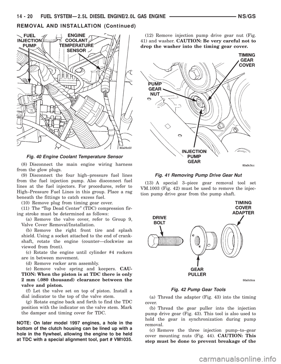
(8) Disconnect the main engine wiring harness
from the glow plugs.
(9) Disconnect the four high±pressure fuel lines
from the fuel injection pump. Also disconnect fuel
lines at the fuel injectors. For procedures, refer to
High±Pressure Fuel Lines in this group. Place a rag
beneath the fittings to catch excess fuel.
(10) Remove plug from timing gear cover.
(11) The ªTop Dead Centerº (TDC) compression fir-
ing stroke must be determined as follows:
(a) Remove the valve cover, refer to Group 9,
Valve Cover Removal/Installation.
(b) Remove the right front tire and splash
shield. Using a socket attached to the end of crank-
shaft, rotate the engine (counterÐclockwise as
viewed from front).
(c) Rotate the engine until cylinder #4 rockers
are in between movement.
(d) Remove rocker arm assembly.
(e) Remove valve spring and keepers.CAU-
TION: When the piston is at TDC there is only
2 mm (.080 thousand) clearance between the
valve and piston.
(f) Let the valve set on top of piston. Install a
dial indicator to the top of the valve stem.
(g) Rotate engine back and forth to find the TDC
position with the indicator on the valve stem. Mark
the damper and timing cover for TDC.
NOTE: On later model 1997 engines, a hole in the
bottom of the clutch housing can be lined up with a
hole in the flywheel, allowing the engine to be held
at TDC with a special alignment tool, part # VM1035.(12) Remove injection pump drive gear nut (Fig.
41) and washer.CAUTION: Be very careful not to
drop the washer into the timing gear cover.
(13) A special 3±piece gear removal tool set
VM.1003 (Fig. 42) must be used to remove the injec-
tion pump drive gear from the pump shaft.
(a) Thread the adapter (Fig. 43) into the timing
cover.
(b) Thread the gear puller into the injection
pump drive gear (Fig. 43). This tool is also used to
hold the gear in synchronization during pump
removal.
(c) Remove the three injection pump±to±gear
cover mounting nuts (Fig. 44).CAUTION: This
step must be done to prevent breakage of the
Fig. 40 Engine Coolant Temperature Sensor
Fig. 41 Removing Pump Drive Gear Nut
Fig. 42 Pump Gear Tools
14 - 20 FUEL SYSTEMÐ2.5L DIESEL ENGINE/2.0L GAS ENGINENS/GS
REMOVAL AND INSTALLATION (Continued)
Page 1431 of 1938
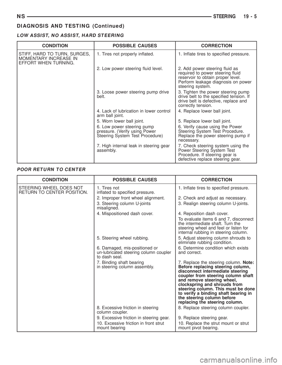
LOW ASSIST, NO ASSIST, HARD STEERING
POOR RETURN TO CENTER
CONDITION POSSIBLE CAUSES CORRECTION
STIFF, HARD TO TURN, SURGES,
MOMENTARY INCREASE IN
EFFORT WHEN TURNING.1. Tires not properly inflated. 1. Inflate tires to specified pressure.
2. Low power steering fluid level. 2. Add power steering fluid as
required to power steering fluid
reservoir to obtain proper level.
Perform leakage diagnosis on power
steering system.
3. Loose power steering pump drive
belt.3. Tighten the power steering pump
drive belt to the specified tension. If
drive belt is defective, replace and
correctly tension.
4. Lack of lubrication in lower control
arm ball joint.4. Replace lower ball joint.
5. Worn lower ball joint. 5. Replace lower ball joint.
6. Low power steering pump
pressure. (Verify using Power
Steering System Test Procedure)6. Verify cause using the Power
Steering System Test Procedure.
Replace the power steering pump if
necessary.
7. High internal leak in steering gear
assembly.7. Check steering system using the
Power Steering System Test
Procedure. If steering gear is
defective replace steering gear.
CONDITION POSSIBLE CAUSES CORRECTION
STEERING WHEEL DOES NOT
RETURN TO CENTER POSITION.1. Tires not
inflated to specified pressure.1. Inflate tires to specified pressure.
2. Improper front wheel alignment. 2. Check and adjust as necessary.
3. Steering column U-joints
misaligned.3. Realign steering column U-joints.
4. Mispositioned dash cover. 4. Reposition dash cover.
To evaluate items 6 and 7, disconnect
the intermediate shaft. Turn the
steering wheel and feel or listen for
internal rubbing in steering column.
5. Steering wheel rubbing. 5. Adjust steering column shrouds to
eliminate rubbing condition.
6. Damaged, mis-positioned or
un-lubricated steering column coupler
to dash seal.6. Determine condition which exists
and correct.
7. Binding shaft bearing
in steering column assembly.7. Replace the steering column.Note:
Before replacing steering column,
disconnect intermediate steering
coupler from steering column shaft
and remove steering wheel,
clockspring and shrouds from
steering column. This must be done
to verify a binding shaft bearing in
the steering column before
replacing the steering column.
8. Excessive friction in steering
column coupler.8. Replace steering column coupler.
9. Excessive friction in steering gear. 9. Replace steering gear.
10. Excessive friction in front strut
mount bearing10. Replace the strut mount or strut
mount pivot bearing.
NSSTEERING 19 - 5
DIAGNOSIS AND TESTING (Continued)
Page 1433 of 1938
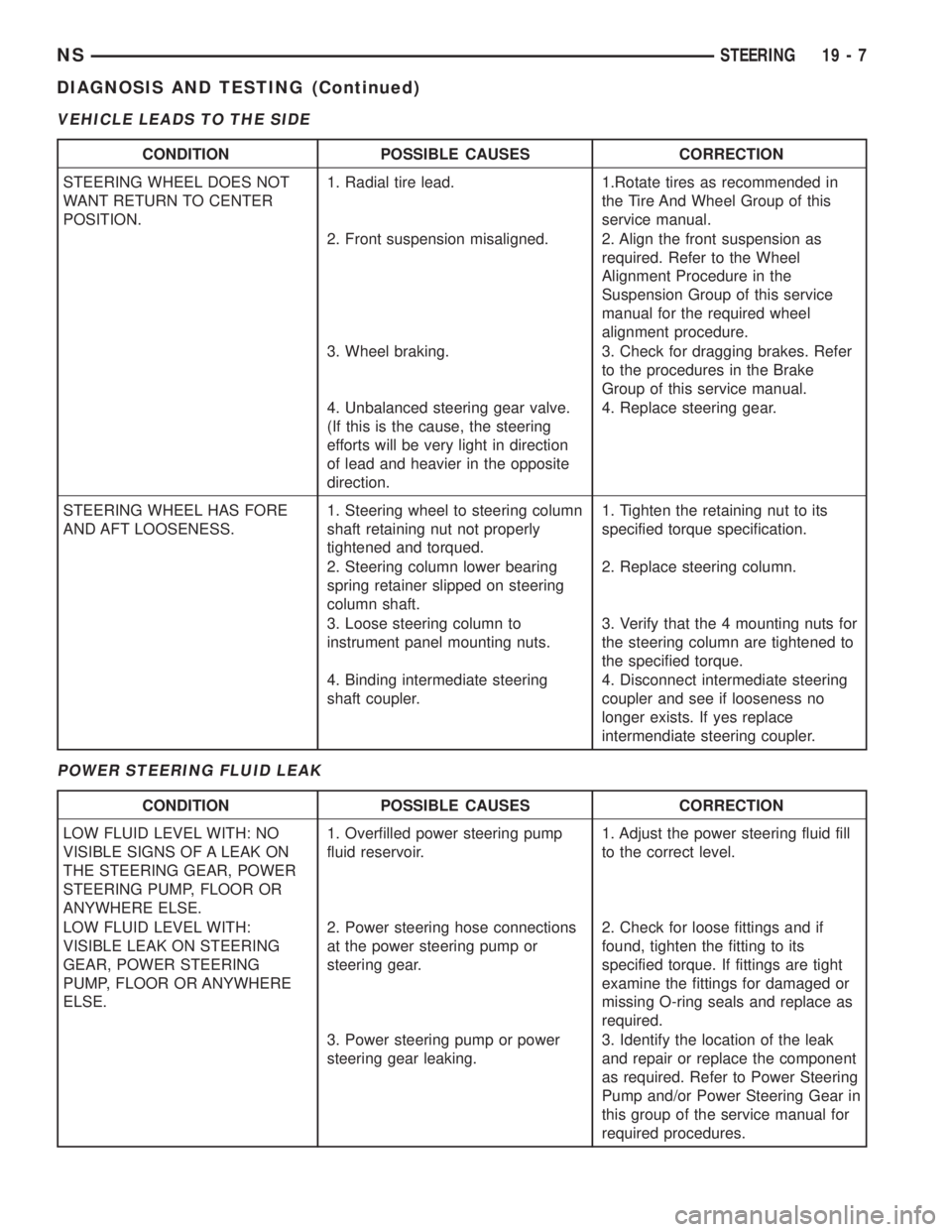
VEHICLE LEADS TO THE SIDE
POWER STEERING FLUID LEAK
CONDITION POSSIBLE CAUSES CORRECTION
STEERING WHEEL DOES NOT
WANT RETURN TO CENTER
POSITION.1. Radial tire lead. 1.Rotate tires as recommended in
the Tire And Wheel Group of this
service manual.
2. Front suspension misaligned. 2. Align the front suspension as
required. Refer to the Wheel
Alignment Procedure in the
Suspension Group of this service
manual for the required wheel
alignment procedure.
3. Wheel braking. 3. Check for dragging brakes. Refer
to the procedures in the Brake
Group of this service manual.
4. Unbalanced steering gear valve.
(If this is the cause, the steering
efforts will be very light in direction
of lead and heavier in the opposite
direction.4. Replace steering gear.
STEERING WHEEL HAS FORE
AND AFT LOOSENESS.1. Steering wheel to steering column
shaft retaining nut not properly
tightened and torqued.1. Tighten the retaining nut to its
specified torque specification.
2. Steering column lower bearing
spring retainer slipped on steering
column shaft.2. Replace steering column.
3. Loose steering column to
instrument panel mounting nuts.3. Verify that the 4 mounting nuts for
the steering column are tightened to
the specified torque.
4. Binding intermediate steering
shaft coupler.4. Disconnect intermediate steering
coupler and see if looseness no
longer exists. If yes replace
intermendiate steering coupler.
CONDITION POSSIBLE CAUSES CORRECTION
LOW FLUID LEVEL WITH: NO
VISIBLE SIGNS OF A LEAK ON
THE STEERING GEAR, POWER
STEERING PUMP, FLOOR OR
ANYWHERE ELSE.1. Overfilled power steering pump
fluid reservoir.1. Adjust the power steering fluid fill
to the correct level.
LOW FLUID LEVEL WITH:
VISIBLE LEAK ON STEERING
GEAR, POWER STEERING
PUMP, FLOOR OR ANYWHERE
ELSE.2. Power steering hose connections
at the power steering pump or
steering gear.2. Check for loose fittings and if
found, tighten the fitting to its
specified torque. If fittings are tight
examine the fittings for damaged or
missing O-ring seals and replace as
required.
3. Power steering pump or power
steering gear leaking.3. Identify the location of the leak
and repair or replace the component
as required. Refer to Power Steering
Pump and/or Power Steering Gear in
this group of the service manual for
required procedures.
NSSTEERING 19 - 7
DIAGNOSIS AND TESTING (Continued)
Page 1459 of 1938
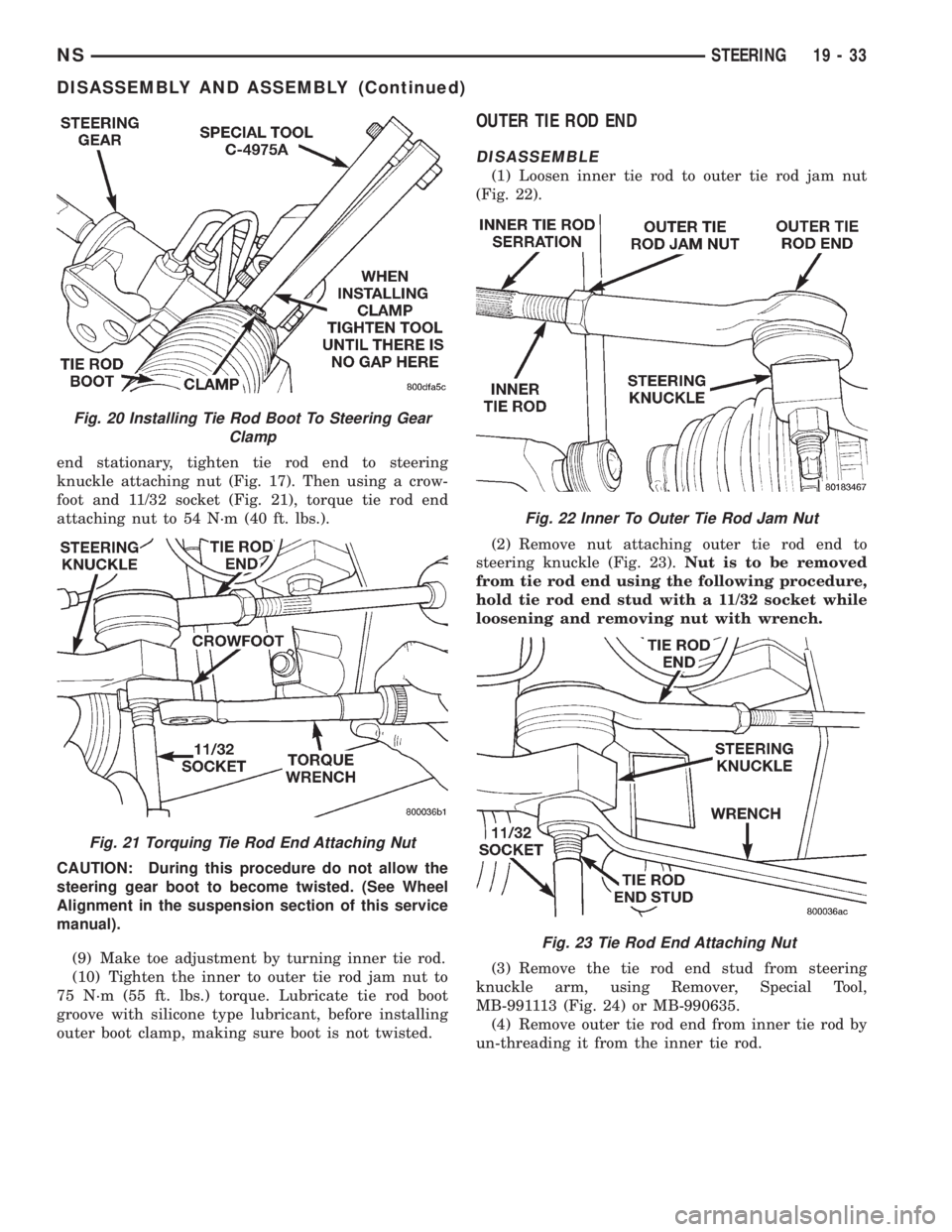
end stationary, tighten tie rod end to steering
knuckle attaching nut (Fig. 17). Then using a crow-
foot and 11/32 socket (Fig. 21), torque tie rod end
attaching nut to 54 N´m (40 ft. lbs.).
CAUTION: During this procedure do not allow the
steering gear boot to become twisted. (See Wheel
Alignment in the suspension section of this service
manual).
(9) Make toe adjustment by turning inner tie rod.
(10) Tighten the inner to outer tie rod jam nut to
75 N´m (55 ft. lbs.) torque. Lubricate tie rod boot
groove with silicone type lubricant, before installing
outer boot clamp, making sure boot is not twisted.
OUTER TIE ROD END
DISASSEMBLE
(1) Loosen inner tie rod to outer tie rod jam nut
(Fig. 22).
(2) Remove nut attaching outer tie rod end to
steering knuckle (Fig. 23).Nut is to be removed
from tie rod end using the following procedure,
hold tie rod end stud with a 11/32 socket while
loosening and removing nut with wrench.
(3) Remove the tie rod end stud from steering
knuckle arm, using Remover, Special Tool,
MB-991113 (Fig. 24) or MB-990635.
(4) Remove outer tie rod end from inner tie rod by
un-threading it from the inner tie rod.
Fig. 20 Installing Tie Rod Boot To Steering Gear
Clamp
Fig. 21 Torquing Tie Rod End Attaching Nut
Fig. 22 Inner To Outer Tie Rod Jam Nut
Fig. 23 Tie Rod End Attaching Nut
NSSTEERING 19 - 33
DISASSEMBLY AND ASSEMBLY (Continued)