1996 CHRYSLER VOYAGER hood open
[x] Cancel search: hood openPage 1755 of 1938
may be necessary to use a soldering gun to melt
the newly applied material. Do not over heat the
affected area, damage to the exterior of the trim
panel may occur.
(4) Allow the repaired area to cool and verify the
repair.
(5) Install trim panel.
REMOVAL AND INSTALLATION
A-PILLAR LOWER EXTENSION TRIM
REMOVAL
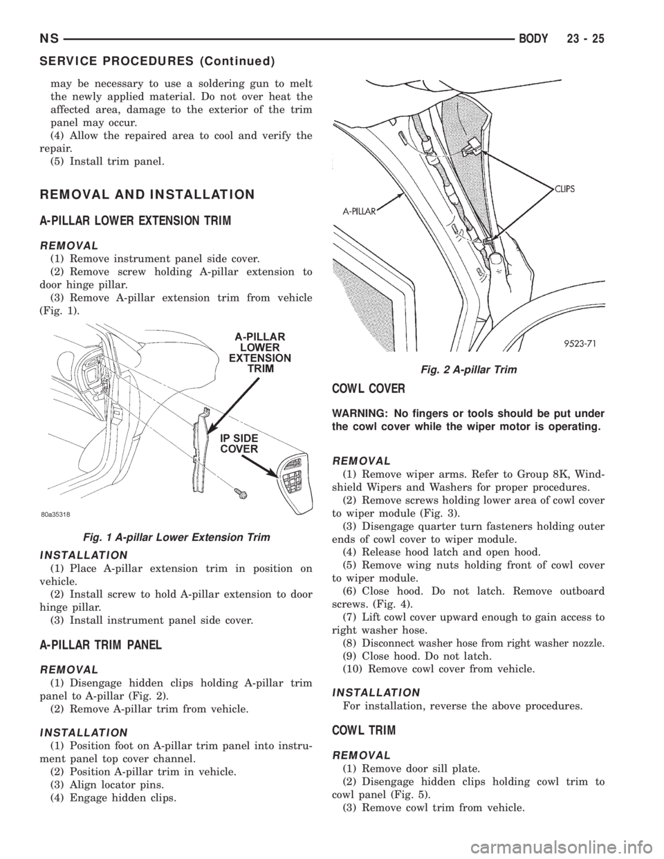
(1) Remove instrument panel side cover.
(2) Remove screw holding A-pillar extension to
door hinge pillar.
(3) Remove A-pillar extension trim from vehicle
(Fig. 1).
INSTALLATION
(1) Place A-pillar extension trim in position on
vehicle.
(2) Install screw to hold A-pillar extension to door
hinge pillar.
(3) Install instrument panel side cover.
A-PILLAR TRIM PANEL
REMOVAL
(1) Disengage hidden clips holding A-pillar trim
panel to A-pillar (Fig. 2).
(2) Remove A-pillar trim from vehicle.
INSTALLATION
(1) Position foot on A-pillar trim panel into instru-
ment panel top cover channel.
(2) Position A-pillar trim in vehicle.
(3) Align locator pins.
(4) Engage hidden clips.
COWL COVER
WARNING: No fingers or tools should be put under
the cowl cover while the wiper motor is operating.
REMOVAL
(1) Remove wiper arms. Refer to Group 8K, Wind-
shield Wipers and Washers for proper procedures.
(2) Remove screws holding lower area of cowl cover
to wiper module (Fig. 3).
(3) Disengage quarter turn fasteners holding outer
ends of cowl cover to wiper module.
(4) Release hood latch and open hood.
(5) Remove wing nuts holding front of cowl cover
to wiper module.
(6) Close hood. Do not latch. Remove outboard
screws. (Fig. 4).
(7) Lift cowl cover upward enough to gain access to
right washer hose.
(8) D
isconnect washer hose from right washer nozzle.
(9) Close hood. Do not latch.
(10) Remove cowl cover from vehicle.
INSTALLATION
For installation, reverse the above procedures.
COWL TRIM
REMOVAL
(1) Remove door sill plate.
(2) Disengage hidden clips holding cowl trim to
cowl panel (Fig. 5).
(3) Remove cowl trim from vehicle.
Fig. 1 A-pillar Lower Extension Trim
Fig. 2 A-pillar Trim
NSBODY 23 - 25
SERVICE PROCEDURES (Continued)
Page 1770 of 1938
(5) Remove A-pillar trim covers.
(6) Remove B-pillar upper trim covers.
(7) Remove C-pillar upper trim covers.
(8) Remove D-pillar upper trim covers.
(9) Remove rear door opening header trim.
(10) If equipped, remove overhead console.
(11) If equipped, remove reading lamp.
(12) Remove dome lamp.
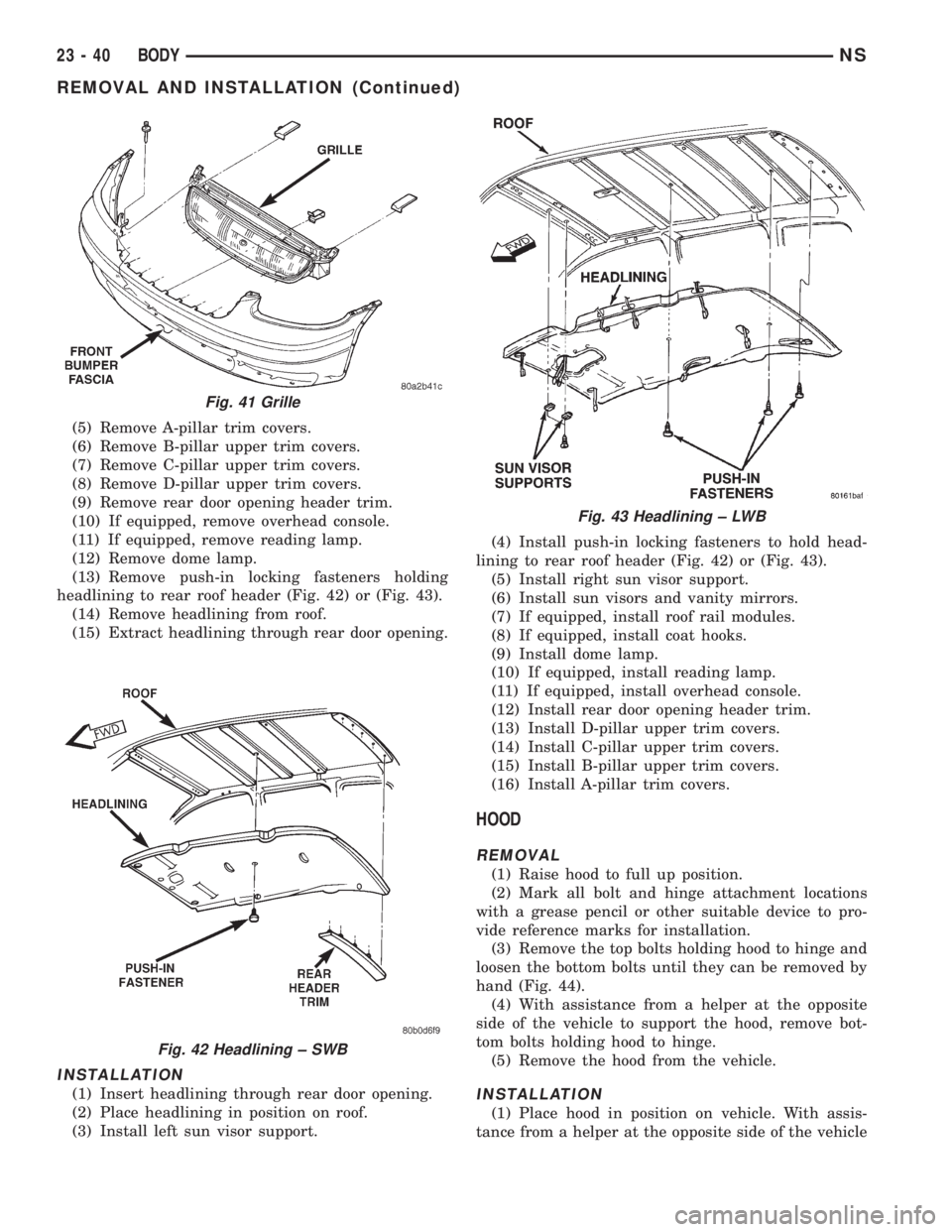
(13) Remove push-in locking fasteners holding
headlining to rear roof header (Fig. 42) or (Fig. 43).
(14) Remove headlining from roof.
(15) Extract headlining through rear door opening.
INSTALLATION
(1) Insert headlining through rear door opening.
(2) Place headlining in position on roof.
(3) Install left sun visor support.(4) Install push-in locking fasteners to hold head-
lining to rear roof header (Fig. 42) or (Fig. 43).
(5) Install right sun visor support.
(6) Install sun visors and vanity mirrors.
(7) If equipped, install roof rail modules.
(8) If equipped, install coat hooks.
(9) Install dome lamp.
(10) If equipped, install reading lamp.
(11) If equipped, install overhead console.
(12) Install rear door opening header trim.
(13) Install D-pillar upper trim covers.
(14) Install C-pillar upper trim covers.
(15) Install B-pillar upper trim covers.
(16) Install A-pillar trim covers.
HOOD
REMOVAL
(1) Raise hood to full up position.
(2) Mark all bolt and hinge attachment locations
with a grease pencil or other suitable device to pro-
vide reference marks for installation.
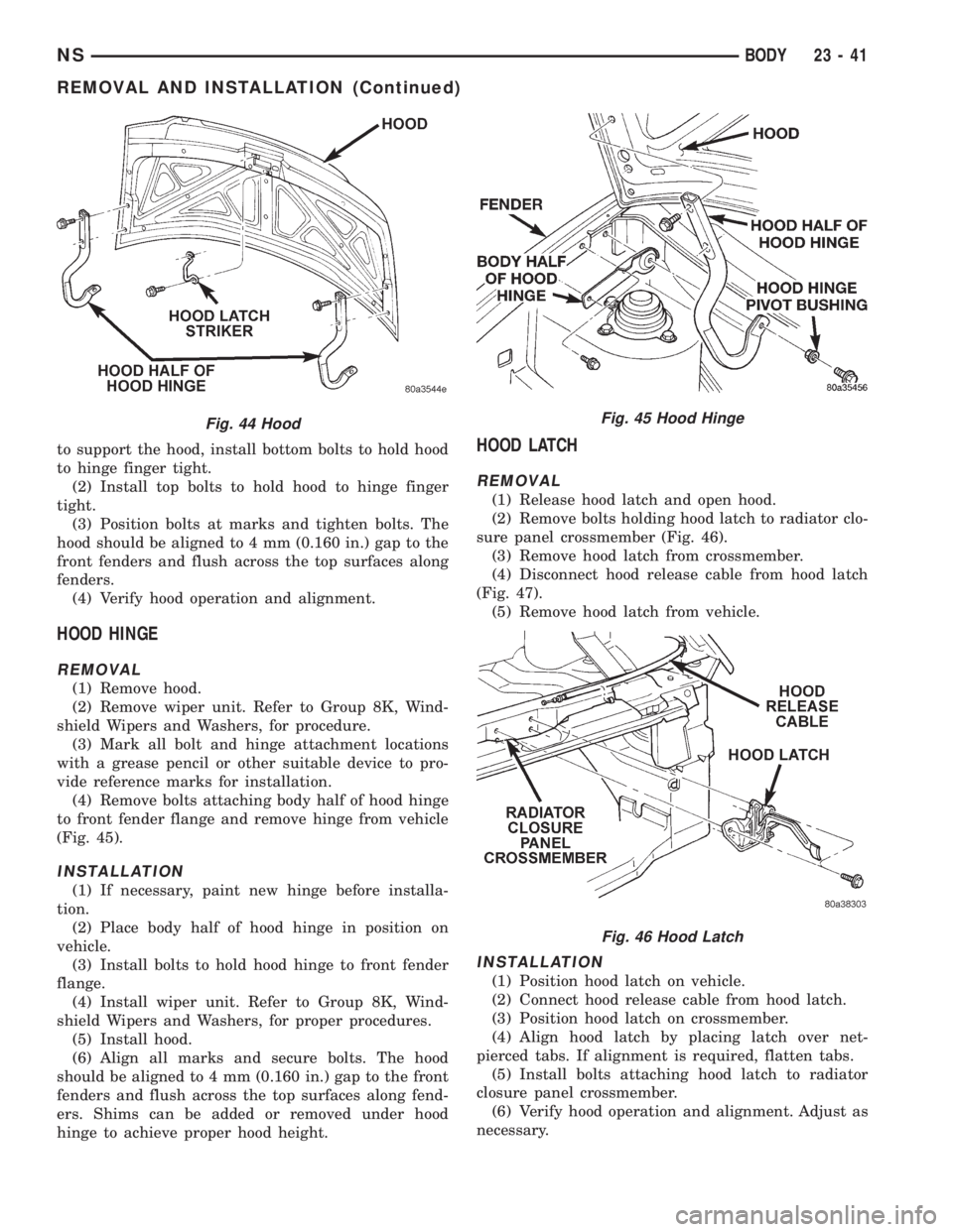
(3) Remove the top bolts holding hood to hinge and
loosen the bottom bolts until they can be removed by
hand (Fig. 44).
(4) With assistance from a helper at the opposite
side of the vehicle to support the hood, remove bot-
tom bolts holding hood to hinge.
(5) Remove the hood from the vehicle.
INSTALLATION
(1) Place hood in position on vehicle. With assis-
tance from a helper at the opposite side of the vehicle
Fig. 41 Grille
Fig. 42 Headlining ± SWB
Fig. 43 Headlining ± LWB
23 - 40 BODYNS
REMOVAL AND INSTALLATION (Continued)
Page 1771 of 1938
to support the hood, install bottom bolts to hold hood
to hinge finger tight.
(2) Install top bolts to hold hood to hinge finger
tight.
(3) Position bolts at marks and tighten bolts. The
hood should be aligned to 4 mm (0.160 in.) gap to the
front fenders and flush across the top surfaces along
fenders.
(4) Verify hood operation and alignment.
HOOD HINGE
REMOVAL
(1) Remove hood.
(2) Remove wiper unit. Refer to Group 8K, Wind-
shield Wipers and Washers, for procedure.
(3) Mark all bolt and hinge attachment locations
with a grease pencil or other suitable device to pro-
vide reference marks for installation.
(4) Remove bolts attaching body half of hood hinge
to front fender flange and remove hinge from vehicle
(Fig. 45).
INSTALLATION
(1) If necessary, paint new hinge before installa-
tion.
(2) Place body half of hood hinge in position on
vehicle.
(3) Install bolts to hold hood hinge to front fender
flange.
(4) Install wiper unit. Refer to Group 8K, Wind-
shield Wipers and Washers, for proper procedures.
(5) Install hood.
(6) Align all marks and secure bolts. The hood
should be aligned to 4 mm (0.160 in.) gap to the front
fenders and flush across the top surfaces along fend-
ers. Shims can be added or removed under hood
hinge to achieve proper hood height.
HOOD LATCH
REMOVAL
(1) Release hood latch and open hood.
(2) Remove bolts holding hood latch to radiator clo-
sure panel crossmember (Fig. 46).
(3) Remove hood latch from crossmember.
(4) Disconnect hood release cable from hood latch
(Fig. 47).
(5) Remove hood latch from vehicle.
INSTALLATION
(1) Position hood latch on vehicle.
(2) Connect hood release cable from hood latch.
(3) Position hood latch on crossmember.
(4) Align hood latch by placing latch over net-
pierced tabs. If alignment is required, flatten tabs.
(5) Install bolts attaching hood latch to radiator
closure panel crossmember.
(6) Verify hood operation and alignment. Adjust as
necessary.
Fig. 44 HoodFig. 45 Hood Hinge
Fig. 46 Hood Latch
NSBODY 23 - 41
REMOVAL AND INSTALLATION (Continued)
Page 1772 of 1938
(7) Tighten attaching bolts to 11 to 16 N´m (100 to
140 in. lbs.) torque.
HOOD LATCH STRIKER
REMOVAL
(1) Release hood latch and open hood.
(2) Remove bolts holding striker to inside of hood
(Fig. 44).
(3) Remove hood latch striker from vehicle.
INSTALLATION
(1) Position hood latch striker on vehicle.
(2) Install bolts to hold hood latch striker to hood.
(3) Align hood latch striker to engage smoothly
into hood latch.
(4) Verify hood operation and alignment. Adjust as
necessary.
(5) Tighten attaching bolts to 11 to 16 N´m (100 to
140 in. lbs.) torque.
HOOD RELEASE CABLE
REMOVAL
(1) Remove hood latch.
(2) Disengage cable end from hood latch locking
mechanism.
(3) Slide cable case end sideways in keyhole slot of
hood latch while pinching barb on cable case closed.
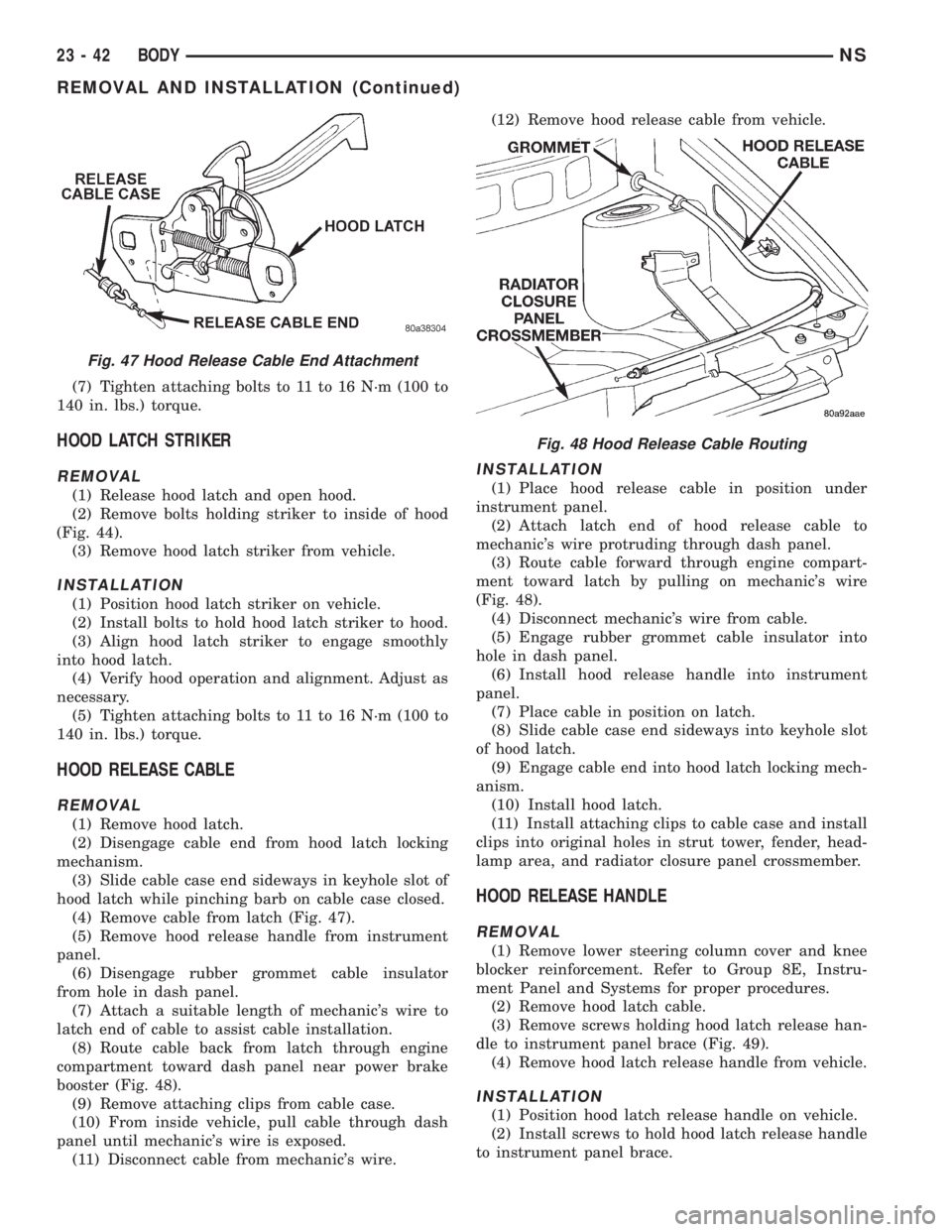
(4) Remove cable from latch (Fig. 47).
(5) Remove hood release handle from instrument
panel.
(6) Disengage rubber grommet cable insulator
from hole in dash panel.
(7) Attach a suitable length of mechanic's wire to
latch end of cable to assist cable installation.
(8) Route cable back from latch through engine
compartment toward dash panel near power brake
booster (Fig. 48).
(9) Remove attaching clips from cable case.
(10) From inside vehicle, pull cable through dash
panel until mechanic's wire is exposed.
(11) Disconnect cable from mechanic's wire.(12) Remove hood release cable from vehicle.
INSTALLATION
(1) Place hood release cable in position under
instrument panel.
(2) Attach latch end of hood release cable to
mechanic's wire protruding through dash panel.
(3) Route cable forward through engine compart-
ment toward latch by pulling on mechanic's wire
(Fig. 48).
(4) Disconnect mechanic's wire from cable.
(5) Engage rubber grommet cable insulator into
hole in dash panel.
(6) Install hood release handle into instrument
panel.
(7) Place cable in position on latch.
(8) Slide cable case end sideways into keyhole slot
of hood latch.
(9) Engage cable end into hood latch locking mech-
anism.
(10) Install hood latch.
(11) Install attaching clips to cable case and install
clips into original holes in strut tower, fender, head-
lamp area, and radiator closure panel crossmember.
HOOD RELEASE HANDLE
REMOVAL
(1) Remove lower steering column cover and knee
blocker reinforcement. Refer to Group 8E, Instru-
ment Panel and Systems for proper procedures.
(2) Remove hood latch cable.
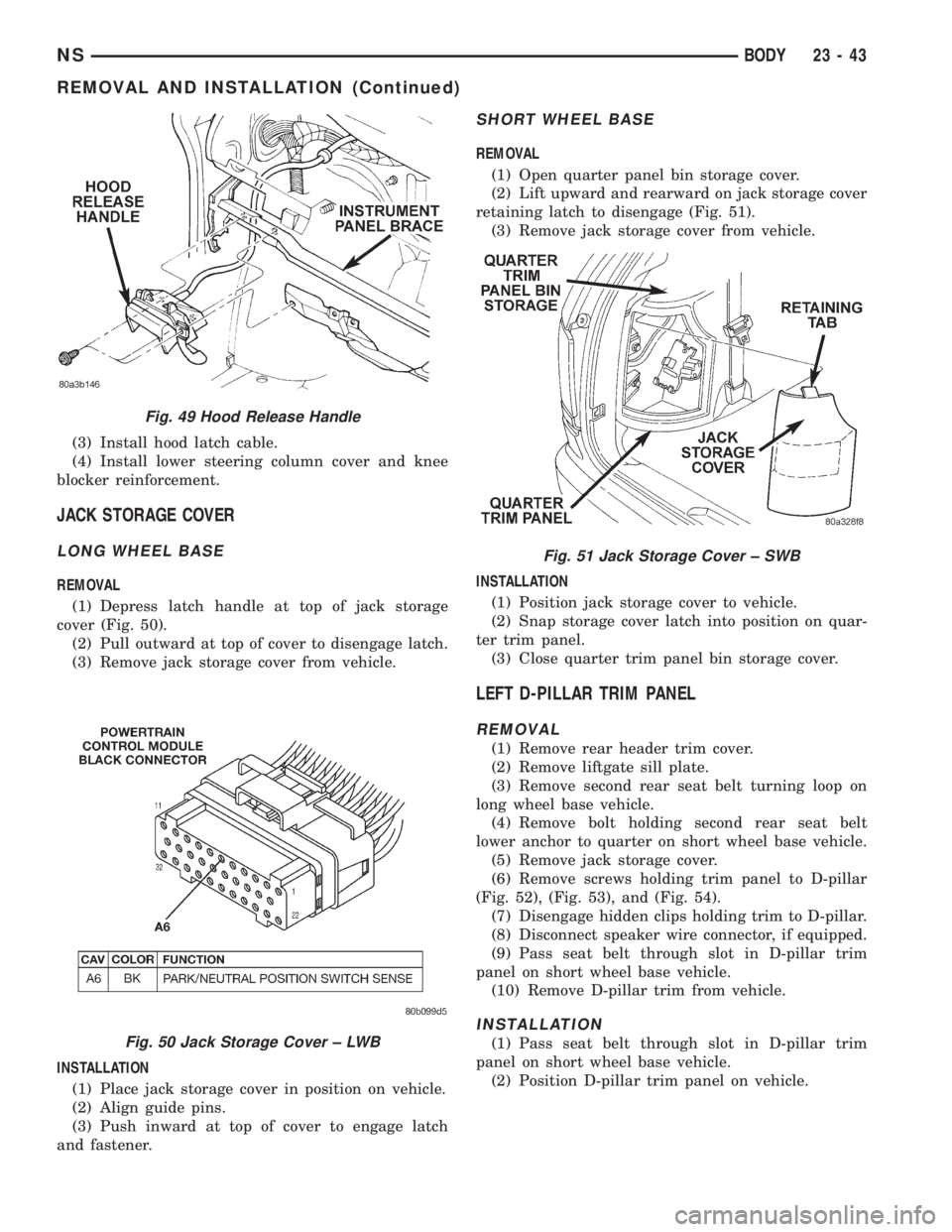
(3) Remove screws holding hood latch release han-
dle to instrument panel brace (Fig. 49).
(4) Remove hood latch release handle from vehicle.
INSTALLATION
(1) Position hood latch release handle on vehicle.
(2) Install screws to hold hood latch release handle
to instrument panel brace.
Fig. 47 Hood Release Cable End Attachment
Fig. 48 Hood Release Cable Routing
23 - 42 BODYNS
REMOVAL AND INSTALLATION (Continued)
Page 1773 of 1938
(3) Install hood latch cable.
(4) Install lower steering column cover and knee
blocker reinforcement.
JACK STORAGE COVER
LONG WHEEL BASE
REMOVAL
(1) Depress latch handle at top of jack storage
cover (Fig. 50).
(2) Pull outward at top of cover to disengage latch.
(3) Remove jack storage cover from vehicle.
INSTALLATION
(1) Place jack storage cover in position on vehicle.
(2) Align guide pins.
(3) Push inward at top of cover to engage latch
and fastener.
SHORT WHEEL BASE
REMOVAL
(1) Open quarter panel bin storage cover.
(2) Lift upward and rearward on jack storage cover
retaining latch to disengage (Fig. 51).
(3) Remove jack storage cover from vehicle.
INSTALLATION
(1) Position jack storage cover to vehicle.
(2) Snap storage cover latch into position on quar-
ter trim panel.
(3) Close quarter trim panel bin storage cover.
LEFT D-PILLAR TRIM PANEL
REMOVAL
(1) Remove rear header trim cover.
(2) Remove liftgate sill plate.
(3) Remove second rear seat belt turning loop on
long wheel base vehicle.
(4) Remove bolt holding second rear seat belt
lower anchor to quarter on short wheel base vehicle.
(5) Remove jack storage cover.
(6) Remove screws holding trim panel to D-pillar
(Fig. 52), (Fig. 53), and (Fig. 54).
(7) Disengage hidden clips holding trim to D-pillar.
(8) Disconnect speaker wire connector, if equipped.
(9) Pass seat belt through slot in D-pillar trim
panel on short wheel base vehicle.
(10) Remove D-pillar trim from vehicle.
INSTALLATION
(1) Pass seat belt through slot in D-pillar trim
panel on short wheel base vehicle.
(2) Position D-pillar trim panel on vehicle.
Fig. 49 Hood Release Handle
Fig. 50 Jack Storage Cover ± LWB
Fig. 51 Jack Storage Cover ± SWB
NSBODY 23 - 43
REMOVAL AND INSTALLATION (Continued)
Page 1783 of 1938
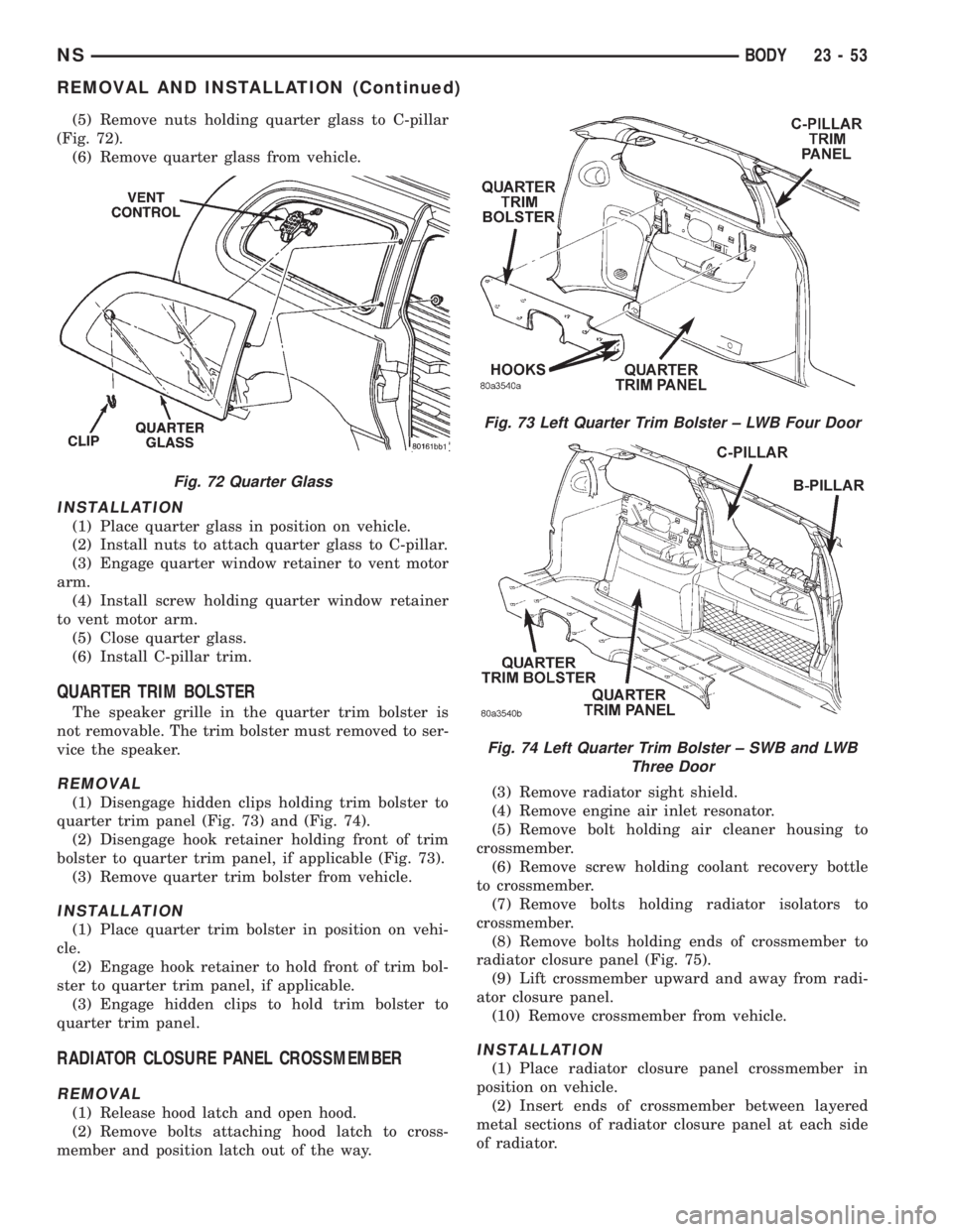
(5) Remove nuts holding quarter glass to C-pillar
(Fig. 72).
(6) Remove quarter glass from vehicle.
INSTALLATION
(1) Place quarter glass in position on vehicle.
(2) Install nuts to attach quarter glass to C-pillar.
(3) Engage quarter window retainer to vent motor
arm.
(4) Install screw holding quarter window retainer
to vent motor arm.
(5) Close quarter glass.
(6) Install C-pillar trim.
QUARTER TRIM BOLSTER
The speaker grille in the quarter trim bolster is
not removable. The trim bolster must removed to ser-
vice the speaker.
REMOVAL
(1) Disengage hidden clips holding trim bolster to
quarter trim panel (Fig. 73) and (Fig. 74).
(2) Disengage hook retainer holding front of trim
bolster to quarter trim panel, if applicable (Fig. 73).
(3) Remove quarter trim bolster from vehicle.
INSTALLATION
(1) Place quarter trim bolster in position on vehi-
cle.
(2) Engage hook retainer to hold front of trim bol-
ster to quarter trim panel, if applicable.
(3) Engage hidden clips to hold trim bolster to
quarter trim panel.
RADIATOR CLOSURE PANEL CROSSMEMBER
REMOVAL
(1) Release hood latch and open hood.
(2) Remove bolts attaching hood latch to cross-
member and position latch out of the way.(3) Remove radiator sight shield.
(4) Remove engine air inlet resonator.
(5) Remove bolt holding air cleaner housing to
crossmember.
(6) Remove screw holding coolant recovery bottle
to crossmember.
(7) Remove bolts holding radiator isolators to
crossmember.
(8) Remove bolts holding ends of crossmember to
radiator closure panel (Fig. 75).
(9) Lift crossmember upward and away from radi-
ator closure panel.
(10) Remove crossmember from vehicle.
INSTALLATION
(1) Place radiator closure panel crossmember in
position on vehicle.
(2) Insert ends of crossmember between layered
metal sections of radiator closure panel at each side
of radiator.
Fig. 72 Quarter Glass
Fig. 73 Left Quarter Trim Bolster ± LWB Four Door
Fig. 74 Left Quarter Trim Bolster ± SWB and LWB
Three Door
NSBODY 23 - 53
REMOVAL AND INSTALLATION (Continued)
Page 1784 of 1938
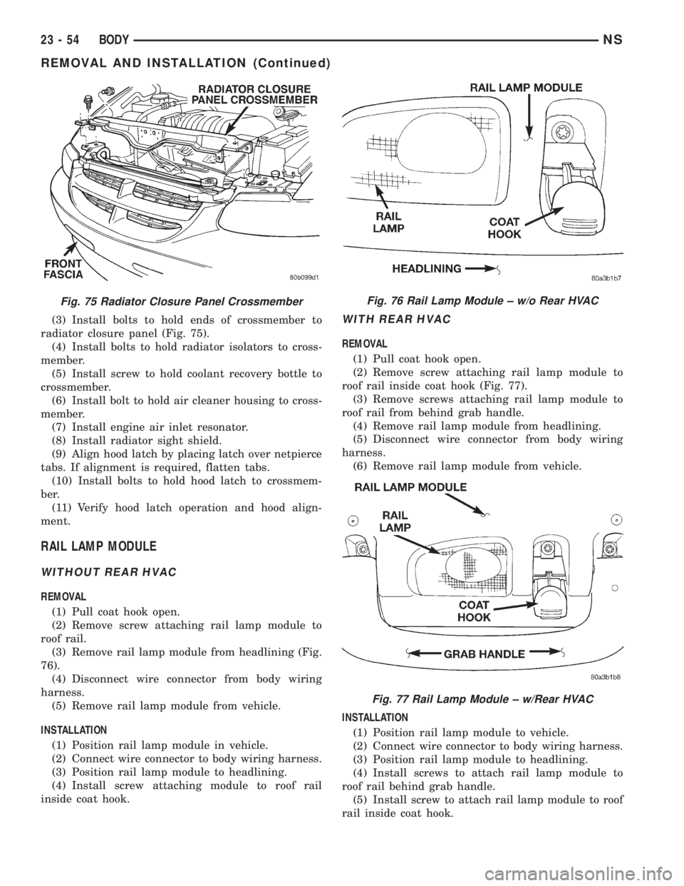
(3) Install bolts to hold ends of crossmember to
radiator closure panel (Fig. 75).
(4) Install bolts to hold radiator isolators to cross-
member.
(5) Install screw to hold coolant recovery bottle to
crossmember.
(6) Install bolt to hold air cleaner housing to cross-
member.
(7) Install engine air inlet resonator.
(8) Install radiator sight shield.
(9) Align hood latch by placing latch over netpierce
tabs. If alignment is required, flatten tabs.
(10) Install bolts to hold hood latch to crossmem-
ber.
(11) Verify hood latch operation and hood align-
ment.
RAIL LAMP MODULE
WITHOUT REAR HVAC
REMOVAL
(1) Pull coat hook open.
(2) Remove screw attaching rail lamp module to
roof rail.
(3) Remove rail lamp module from headlining (Fig.
76).
(4) Disconnect wire connector from body wiring
harness.
(5) Remove rail lamp module from vehicle.
INSTALLATION
(1) Position rail lamp module in vehicle.
(2) Connect wire connector to body wiring harness.
(3) Position rail lamp module to headlining.
(4) Install screw attaching module to roof rail
inside coat hook.
WITH REAR HVAC
REMOVAL
(1) Pull coat hook open.
(2) Remove screw attaching rail lamp module to
roof rail inside coat hook (Fig. 77).
(3) Remove screws attaching rail lamp module to
roof rail from behind grab handle.
(4) Remove rail lamp module from headlining.
(5) Disconnect wire connector from body wiring
harness.
(6) Remove rail lamp module from vehicle.
INSTALLATION
(1) Position rail lamp module to vehicle.
(2) Connect wire connector to body wiring harness.
(3) Position rail lamp module to headlining.
(4) Install screws to attach rail lamp module to
roof rail behind grab handle.
(5) Install screw to attach rail lamp module to roof
rail inside coat hook.
Fig. 75 Radiator Closure Panel CrossmemberFig. 76 Rail Lamp Module ± w/o Rear HVAC
Fig. 77 Rail Lamp Module ± w/Rear HVAC
23 - 54 BODYNS
REMOVAL AND INSTALLATION (Continued)
Page 1837 of 1938
(2) Perform the HVAC Control Calibration Diag-
nostic and Cooldown test. Repeating the test is nec-
essary to clear the fault codes.
BLOWER MOTOR AND WHEEL ASSEMBLY
REMOVAL
(1) Remove glove box. Refer to Group 8E, Instru-
ment Panel and Systems.
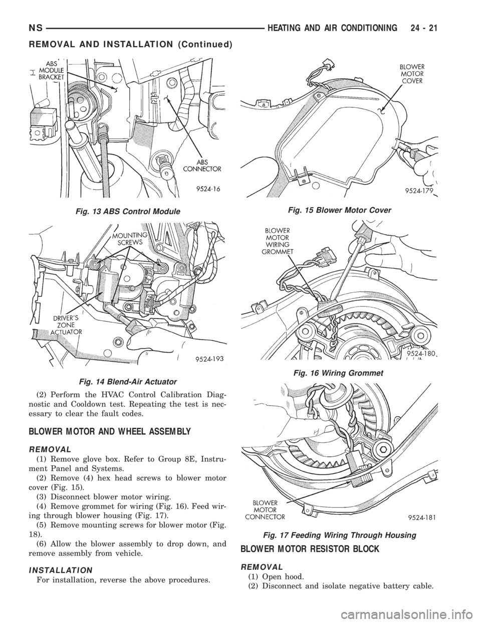
(2) Remove (4) hex head screws to blower motor
cover (Fig. 15).
(3) Disconnect blower motor wiring.
(4) Remove grommet for wiring (Fig. 16). Feed wir-
ing through blower housing (Fig. 17).
(5) Remove mounting screws for blower motor (Fig.
18).
(6) Allow the blower assembly to drop down, and
remove assembly from vehicle.
INSTALLATION
For installation, reverse the above procedures.
BLOWER MOTOR RESISTOR BLOCK
REMOVAL
(1) Open hood.
(2) Disconnect and isolate negative battery cable.
Fig. 13 ABS Control Module
Fig. 14 Blend-Air Actuator
Fig. 15 Blower Motor Cover
Fig. 16 Wiring Grommet
Fig. 17 Feeding Wiring Through Housing
NSHEATING AND AIR CONDITIONING 24 - 21
REMOVAL AND INSTALLATION (Continued)