1996 CHRYSLER VOYAGER battery location
[x] Cancel search: battery locationPage 1039 of 1938
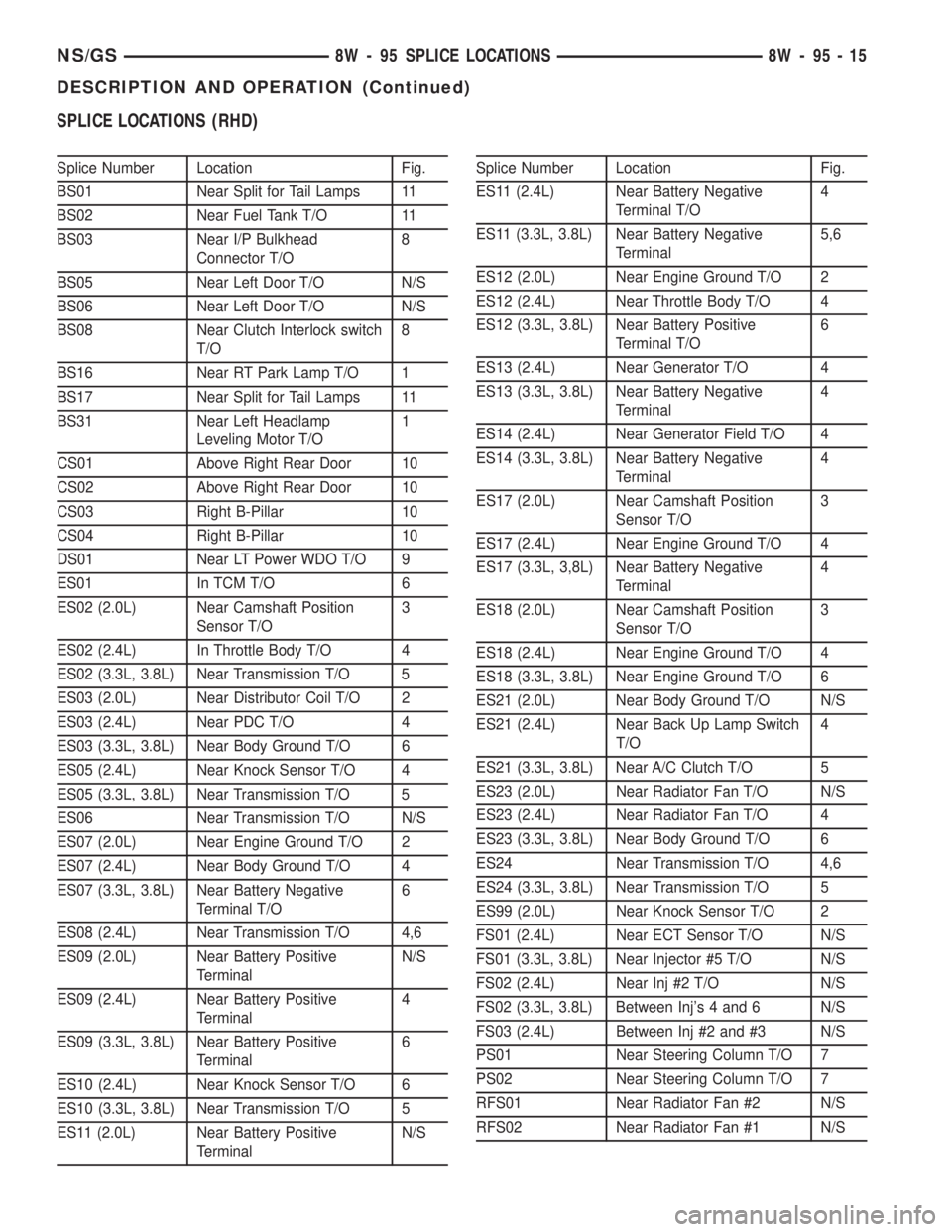
SPLICE LOCATIONS (RHD)
Splice Number Location Fig.
BS01 Near Split for Tail Lamps 11
BS02 Near Fuel Tank T/O 11
BS03 Near I/P Bulkhead
Connector T/O8
BS05 Near Left Door T/O N/S
BS06 Near Left Door T/O N/S
BS08 Near Clutch Interlock switch
T/O8
BS16 Near RT Park Lamp T/O 1
BS17 Near Split for Tail Lamps 11
BS31 Near Left Headlamp
Leveling Motor T/O1
CS01 Above Right Rear Door 10
CS02 Above Right Rear Door 10
CS03 Right B-Pillar 10
CS04 Right B-Pillar 10
DS01 Near LT Power WDO T/O 9
ES01 In TCM T/O 6
ES02 (2.0L) Near Camshaft Position
Sensor T/O3
ES02 (2.4L) In Throttle Body T/O 4
ES02 (3.3L, 3.8L) Near Transmission T/O 5
ES03 (2.0L) Near Distributor Coil T/O 2
ES03 (2.4L) Near PDC T/O 4
ES03 (3.3L, 3.8L) Near Body Ground T/O 6
ES05 (2.4L) Near Knock Sensor T/O 4
ES05 (3.3L, 3.8L) Near Transmission T/O 5
ES06 Near Transmission T/O N/S
ES07 (2.0L) Near Engine Ground T/O 2
ES07 (2.4L) Near Body Ground T/O 4
ES07 (3.3L, 3.8L) Near Battery Negative
Terminal T/O6
ES08 (2.4L) Near Transmission T/O 4,6
ES09 (2.0L) Near Battery Positive
TerminalN/S
ES09 (2.4L) Near Battery Positive
Terminal4
ES09 (3.3L, 3.8L) Near Battery Positive
Terminal6
ES10 (2.4L) Near Knock Sensor T/O 6
ES10 (3.3L, 3.8L) Near Transmission T/O 5
ES11 (2.0L) Near Battery Positive
TerminalN/SSplice Number Location Fig.
ES11 (2.4L) Near Battery Negative
Terminal T/O4
ES11 (3.3L, 3.8L) Near Battery Negative
Terminal5,6
ES12 (2.0L) Near Engine Ground T/O 2
ES12 (2.4L) Near Throttle Body T/O 4
ES12 (3.3L, 3.8L) Near Battery Positive
Terminal T/O6
ES13 (2.4L) Near Generator T/O 4
ES13 (3.3L, 3.8L) Near Battery Negative
Terminal4
ES14 (2.4L) Near Generator Field T/O 4
ES14 (3.3L, 3.8L) Near Battery Negative
Terminal4
ES17 (2.0L) Near Camshaft Position
Sensor T/O3
ES17 (2.4L) Near Engine Ground T/O 4
ES17 (3.3L, 3,8L) Near Battery Negative
Terminal4
ES18 (2.0L) Near Camshaft Position
Sensor T/O3
ES18 (2.4L) Near Engine Ground T/O 4
ES18 (3.3L, 3.8L) Near Engine Ground T/O 6
ES21 (2.0L) Near Body Ground T/O N/S
ES21 (2.4L) Near Back Up Lamp Switch
T/O4
ES21 (3.3L, 3.8L) Near A/C Clutch T/O 5
ES23 (2.0L) Near Radiator Fan T/O N/S
ES23 (2.4L) Near Radiator Fan T/O 4
ES23 (3.3L, 3.8L) Near Body Ground T/O 6
ES24 Near Transmission T/O 4,6
ES24 (3.3L, 3.8L) Near Transmission T/O 5
ES99 (2.0L) Near Knock Sensor T/O 2
FS01 (2.4L) Near ECT Sensor T/O N/S
FS01 (3.3L, 3.8L) Near Injector #5 T/O N/S
FS02 (2.4L) Near Inj #2 T/O N/S
FS02 (3.3L, 3.8L) Between Inj's 4 and 6 N/S
FS03 (2.4L) Between Inj #2 and #3 N/S
PS01 Near Steering Column T/O 7
PS02 Near Steering Column T/O 7
RFS01 Near Radiator Fan #2 N/S
RFS02 Near Radiator Fan #1 N/S
NS/GS8W - 95 SPLICE LOCATIONS 8W - 95 - 15
DESCRIPTION AND OPERATION (Continued)
Page 1055 of 1938
CAUTION: Be sure that the tapped holes maintain
the original centerline.
Heli-Coil tools and inserts are readily available
from automotive parts jobbers.
HYDROSTATIC LOCKED ENGINE
When an engine is suspected to be hydrostatically
locked, regardless of what caused the problem, these
steps should be used.
CAUTION: Do Not Use Starter Motor To Rotate
Engine, severe damage may occur.
(1) Inspect air cleaner, induction system and
intake manifold to insure system is dry and clear of
foreign material.
(2) Remove negative battery cable.
(3) Place a shop towel around the spark plugs
when removing them from the engine. This will catch
any fluid that may possibly be in the cylinder under
pressure.
(4) With all spark plugs removed, rotate engine
crankshaft using a breaker bar and socket.
(5) Identify the fluid in the cylinder(s) (i.e., cool-
ant, fuel, oil or other).
(6) Make sure all fluid has been removed from the
cylinders. Inspect engine for damage (i.e., Connecting
Rods, Pistons, Valves etc.)
(7) Repair engine or components as necessary to
prevent this problem from occurring again.
CAUTION: Squirt approximately 1 teaspoon of oil
into cylinders, rotate engine to lubricate the cylin-
der walls to prevent damage on restart.
(8) Install new spark plugs.
(9) Drain engine oil and remove oil filter.
(10) Fill engine with specified amount of approved
oil and install new oil filter.
(11) Connect negative battery cable.
(12) Start engine and check for any leaks.
ENGINE OIL
Checking Oil Level
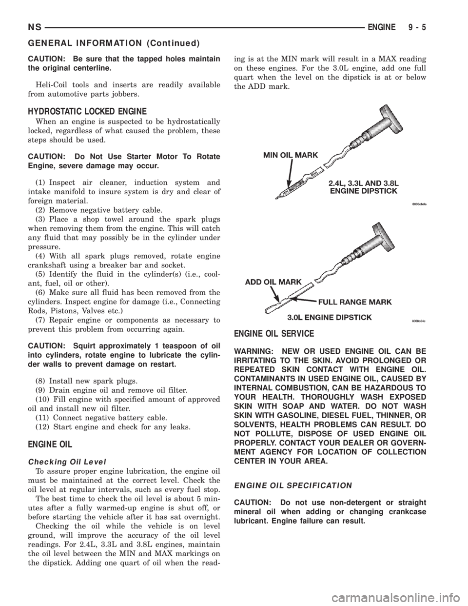
To assure proper engine lubrication, the engine oil
must be maintained at the correct level. Check the
oil level at regular intervals, such as every fuel stop.
The best time to check the oil level is about 5 min-
utes after a fully warmed-up engine is shut off, or
before starting the vehicle after it has sat overnight.
Checking the oil while the vehicle is on level
ground, will improve the accuracy of the oil level
readings. For 2.4L, 3.3L and 3.8L engines, maintain
the oil level between the MIN and MAX markings on
the dipstick. Adding one quart of oil when the read-ing is at the MIN mark will result in a MAX reading
on these engines. For the 3.0L engine, add one full
quart when the level on the dipstick is at or below
the ADD mark.
ENGINE OIL SERVICE
WARNING: NEW OR USED ENGINE OIL CAN BE
IRRITATING TO THE SKIN. AVOID PROLONGED OR
REPEATED SKIN CONTACT WITH ENGINE OIL.
CONTAMINANTS IN USED ENGINE OIL, CAUSED BY
INTERNAL COMBUSTION, CAN BE HAZARDOUS TO
YOUR HEALTH. THOROUGHLY WASH EXPOSED
SKIN WITH SOAP AND WATER. DO NOT WASH
SKIN WITH GASOLINE, DIESEL FUEL, THINNER, OR
SOLVENTS, HEALTH PROBLEMS CAN RESULT. DO
NOT POLLUTE, DISPOSE OF USED ENGINE OIL
PROPERLY. CONTACT YOUR DEALER OR GOVERN-
MENT AGENCY FOR LOCATION OF COLLECTION
CENTER IN YOUR AREA.
ENGINE OIL SPECIFICATION
CAUTION: Do not use non-detergent or straight
mineral oil when adding or changing crankcase
lubricant. Engine failure can result.
NSENGINE 9 - 5
GENERAL INFORMATION (Continued)
Page 1085 of 1938
(4) Install cylinder head cover using procedure out-
lined in this section.
(5) Install rear timing belt cover and timing belt
idler pulley.
(6) Install timing belt and camshaft sprocket.
Refer to procedure outlined in this section.
(7) Install cam sensor and fuel injectors wiring
connectors.
(8) Install coil pack and plug wires onto the
engine. Connect coil pack wiring connector.
(9) Install power steering pump assembly.
(10) Raise vehicle and install the exhaust pipe to
the manifold.
(11) Install power brake vacuum hose to the intake
manifold.
(12) Install accessory drive belts. Refer to Group 7,
Cooling System for procedure.
(13) Install throttle linkage. Refer to Group 14,
Fuel System for procedures.
(14) Install air cleaner and connect all vacuum
lines, electrical wiring and fuel lines to the throttle
body.
(15) Fill cooling system. Refer to Group 7, Cooling
System for procedure. Connect negative battery
cable.
VALVES AND VALVE SPRINGS
REMOVAL
(1) With cylinder head removed, compress valve
springs using a universal valve spring compressor.
(2) Remove valve retaining locks, valve spring
retainers, valve stem seals and valve springs.(3) Before removing valves,remove any burrs
from valve stem lock grooves to prevent dam-
age to the valve guides.Identify valves to insure
installation in original location.
(4) Inspect and clean the valves. Refer to Cleaning
and Inspection outlined in this section for procedure.
INSTALLATION
(1) Coat valve stems with clean engine oil and
insert in cylinder head.
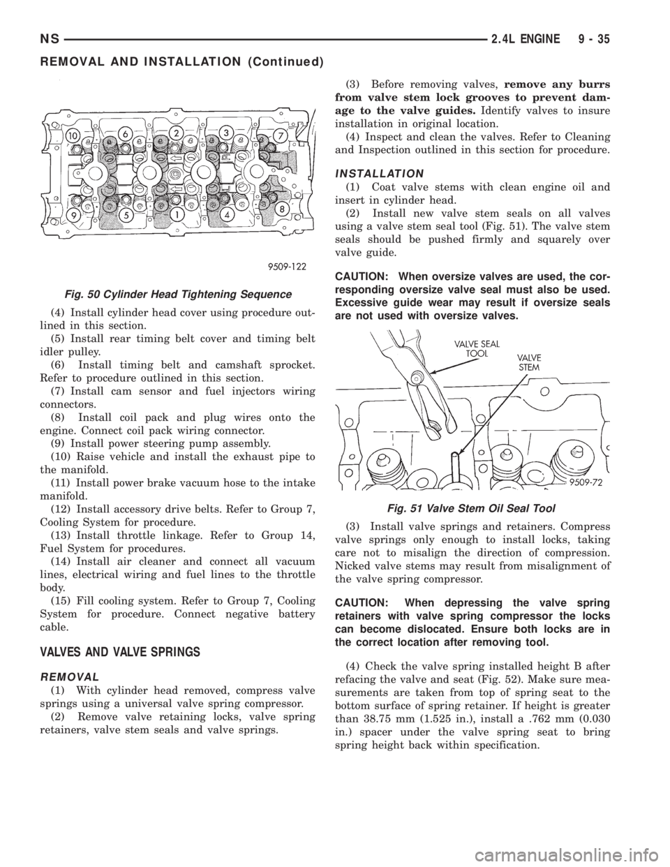
(2) Install new valve stem seals on all valves
using a valve stem seal tool (Fig. 51). The valve stem
seals should be pushed firmly and squarely over
valve guide.
CAUTION: When oversize valves are used, the cor-
responding oversize valve seal must also be used.
Excessive guide wear may result if oversize seals
are not used with oversize valves.
(3) Install valve springs and retainers. Compress
valve springs only enough to install locks, taking
care not to misalign the direction of compression.
Nicked valve stems may result from misalignment of
the valve spring compressor.
CAUTION: When depressing the valve spring
retainers with valve spring compressor the locks
can become dislocated. Ensure both locks are in
the correct location after removing tool.
(4) Check the valve spring installed height B after
refacing the valve and seat (Fig. 52). Make sure mea-
surements are taken from top of spring seat to the
bottom surface of spring retainer. If height is greater
than 38.75 mm (1.525 in.), install a .762 mm (0.030
in.) spacer under the valve spring seat to bring
spring height back within specification.
Fig. 50 Cylinder Head Tightening Sequence
Fig. 51 Valve Stem Oil Seal Tool
NS2.4L ENGINE 9 - 35
REMOVAL AND INSTALLATION (Continued)
Page 1119 of 1938
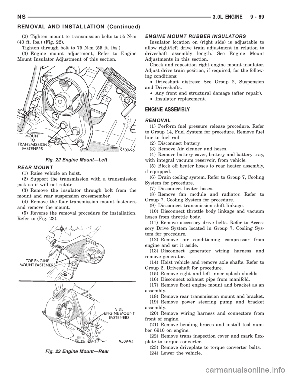
(2) Tighten mount to transmission bolts to 55 N´m
(40 ft. lbs.) (Fig. 22).
Tighten through bolt to 75 N´m (55 ft. lbs.)
(3) Engine mount adjustment, Refer to Engine
Mount Insulator Adjustment of this section.
REAR MOUNT
(1) Raise vehicle on hoist.
(2) Support the transmission with a transmission
jack so it will not rotate.
(3) Remove the insulator through bolt from the
mount and rear suspension crossmember.
(4) Remove the four transmission mount fasteners
and remove the mount.
(5) Reverse the removal procedure for installation.
Refer to (Fig. 23).
ENGINE MOUNT RUBBER INSULATORS
Insulator location on (right side) is adjustable to
allow right/left drive train adjustment in relation to
driveshaft assembly length. See Engine Mount
Adjustments in this section.
Check and reposition right engine mount insulator.
Adjust drive train position, if required, for the follow-
ing conditions:
²Driveshaft distress: See Group 2, Suspension
and Driveshafts.
²Any front end structural damage (after repair).
²Insulator replacement.
ENGINE ASSEMBLY
REMOVAL
(1) Perform fuel pressure release procedure. Refer
to Group 14, Fuel System for procedure. Remove fuel
line to fuel rail.
(2) Disconnect battery.
(3) Remove Air cleaner and hoses.
(4) Remove battery cover, battery and battery tray,
with integral vacuum reservoir, from vehicle.
(5) Block off heater hoses to rear heater assembly,
if equipped.
(6) Drain cooling system. Refer to Group 7, Cooling
System for procedure.
(7) Disconnect heater hoses.
(8) Remove fan module and radiator. Refer to
Group 7, Cooling System for procedure.
(9) Disconnect transmission shift linkage.
(10) Disconnect throttle body linkage and vacuum
hoses from throttle body.
(11) Remove accessory drive belts. Refer to Acces-
sory Drive System located in Group 7, Cooling Sys-
tem for procedure.
(12) Remove air conditioning compressor from
engine and set it aside.
(13) Disconnect generator wiring harness and
remove generator.
(14) Hoist vehicle and remove axle shafts. Refer to
Group 2, Driveshaft for procedure.
(15) Remove right and left inner splash shields.
(16) Disconnect exhaust pipe from manifold.
(17) Remove front engine mount and bracket as an
assembly.
(18) Remove rear transmission mount and bracket.
(19) Remove power steering pump and bracket
assembly.
(20) Remove wiring harness and connectors from
front of engine.
(21) Remove bending braces and install tool num-
ber 6910 on engine.
(22) Remove trans inspection cover and mark flex-
plate to torque converter.
(23) Remove driveplate to torque converter bolts.
(24) Lower the vehicle.
Fig. 22 Engine MountÐLeft
Fig. 23 Engine MountÐRear
NS3.0L ENGINE 9 - 69
REMOVAL AND INSTALLATION (Continued)
Page 1154 of 1938
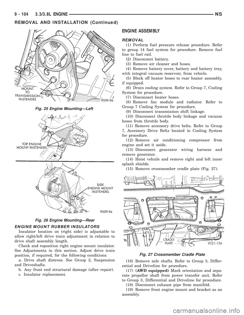
ENGINE MOUNT RUBBER INSULATORS
Insulator location on (right side) is adjustable to
allow right/left drive train adjustment in relation to
drive shaft assembly length.
Check and reposition right engine mount insulator.
See Adjustments in this section. Adjust drive train
position, if required, for the following conditions:
a. Drive shaft distress. See Group 2, Suspension
and Driveshafts.
b. Any front end structural damage (after repair).
c. Insulator replacement.
ENGINE ASSEMBLY
REMOVAL
(1) Perform fuel pressure release procedure. Refer
to group 14 fuel system for procedure. Remove fuel
line to fuel rail.
(2) Disconnect battery.
(3) Remove air cleaner and hoses.
(4) Remove battery cover, battery and battery tray,
with integral vacuum reservoir, from vehicle.
(5) Block off heater hoses to rear heater assembly,
if equipped.
(6) Drain cooling system. Refer to Group 7, Cooling
System for procedure.
(7) Disconnect heater hoses.
(8) Remove fan module and radiator. Refer to
Group 7 Cooling System for procedure.
(9) Disconnect transmission shift linkage.
(10) Disconnect throttle body linkage and vacuum
hoses from throttle body.
(11) Remove accessory drive belts. Refer to Group
7, Accessory Drive Belts located in Cooling System
for procedure.
(12) Remove air conditioning compressor from
engine and set it aside.
(13) Disconnect generator wiring harness and
remove generator.
(14) Hoist vehicle and remove right and left inner
splash shields.
(15) Remove crossmember cradle plate (Fig. 27).
(16) Remove axle shafts. Refer to Group 3, Differ-
ential and Driveline for procedure.
(17)(AWD equipped)Mark orientation and sepa-
rate propeller shaft from power transfer unit. Refer
to Group 3, Differential and Driveline for procedure.
(18) Disconnect exhaust pipe from manifold.
(19) Remove front engine mount and bracket as an
assembly.
Fig. 25 Engine MountingÐLeft
Fig. 26 Engine MountingÐRear
Fig. 27 Crossmember Cradle Plate
9 - 104 3.3/3.8L ENGINENS
REMOVAL AND INSTALLATION (Continued)
Page 1156 of 1938
CRANKSHAFT DAMPER
REMOVAL
(1) Disconnect negative cable from battery.
(2) Raise vehicle on hoist.
(3) Remove right wheel and inner splash shield.
(4) Remove drive belt. Refer to Group 7, Cooling
System for procedure.
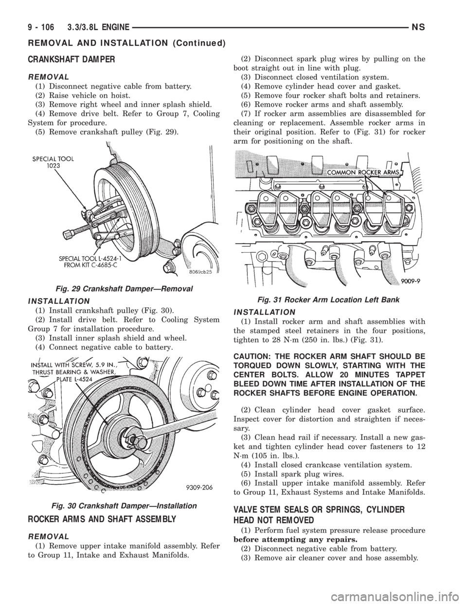
(5) Remove crankshaft pulley (Fig. 29).
INSTALLATION
(1) Install crankshaft pulley (Fig. 30).
(2) Install drive belt. Refer to Cooling System
Group 7 for installation procedure.
(3) Install inner splash shield and wheel.
(4) Connect negative cable to battery.
ROCKER ARMS AND SHAFT ASSEMBLY
REMOVAL
(1) Remove upper intake manifold assembly. Refer
to Group 11, Intake and Exhaust Manifolds.(2) Disconnect spark plug wires by pulling on the
boot straight out in line with plug.
(3) Disconnect closed ventilation system.
(4) Remove cylinder head cover and gasket.
(5) Remove four rocker shaft bolts and retainers.
(6) Remove rocker arms and shaft assembly.
(7) If rocker arm assemblies are disassembled for
cleaning or replacement. Assemble rocker arms in
their original position. Refer to (Fig. 31) for rocker
arm for positioning on the shaft.
INSTALLATION
(1) Install rocker arm and shaft assemblies with
the stamped steel retainers in the four positions,
tighten to 28 N´m (250 in. lbs.) (Fig. 31).
CAUTION: THE ROCKER ARM SHAFT SHOULD BE
TORQUED DOWN SLOWLY, STARTING WITH THE
CENTER BOLTS. ALLOW 20 MINUTES TAPPET
BLEED DOWN TIME AFTER INSTALLATION OF THE
ROCKER SHAFTS BEFORE ENGINE OPERATION.
(2) Clean cylinder head cover gasket surface.
Inspect cover for distortion and straighten if neces-
sary.
(3) Clean head rail if necessary. Install a new gas-
ket and tighten cylinder head cover fasteners to 12
N´m (105 in. lbs.).
(4) Install closed crankcase ventilation system.
(5) Install spark plug wires.
(6) Install upper intake manifold assembly. Refer
to Group 11, Exhaust Systems and Intake Manifolds.
VALVE STEM SEALS OR SPRINGS, CYLINDER
HEAD NOT REMOVED
(1) Perform fuel system pressure release procedure
before attempting any repairs.
(2) Disconnect negative cable from battery.
(3) Remove air cleaner cover and hose assembly.
Fig. 29 Crankshaft DamperÐRemoval
Fig. 30 Crankshaft DamperÐInstallation
Fig. 31 Rocker Arm Location Left Bank
9 - 106 3.3/3.8L ENGINENS
REMOVAL AND INSTALLATION (Continued)
Page 1158 of 1938
²Non±isolatedcylinder head cover to 12 N´m
(105 in. lbs.).
²Isolatedcylinder head cover to 10 N´m (90 in.
lbs.) (Fig. 32).
(4) Connect PCV hose from cylinder head cover.
(5) Install intake manifold upper plenum. Refer to
Group 11, Exhaust System and Intake Manifold for
procedure.
(6) Install Wiper Unit. Refer to Group 8K, Wind-
shield Wipers and Washers for procedure.
(7) Connect negative cable to battery.
CYLINDER HEAD
REMOVAL
(1) Drain cooling system. Refer to Group 7, Cooling
System for procedure and disconnect negative cable
from battery.
(2) Remove upper and lower intake manifolds.
Refer to Group 11, Exhaust System and Intake Man-
ifold.
WARNING: INTAKE MANIFOLD GASKET IS MADE
OF VERY THIN METAL AND MAY CAUSE PER-
SONAL INJURY, HANDLE WITH CARE.
(3) Disconnect coil wires, sending unit wire, heater
hoses and bypass hose.
(4) Remove PCV system hoses, evaporation control
system hose and cylinder head covers.
(5) Remove exhaust manifolds.
(6) Remove rocker arm and shaft assemblies.
Remove push rods andmark positions to ensure
installation in original locations.
(7) Remove the 9 head bolts from each cylinder
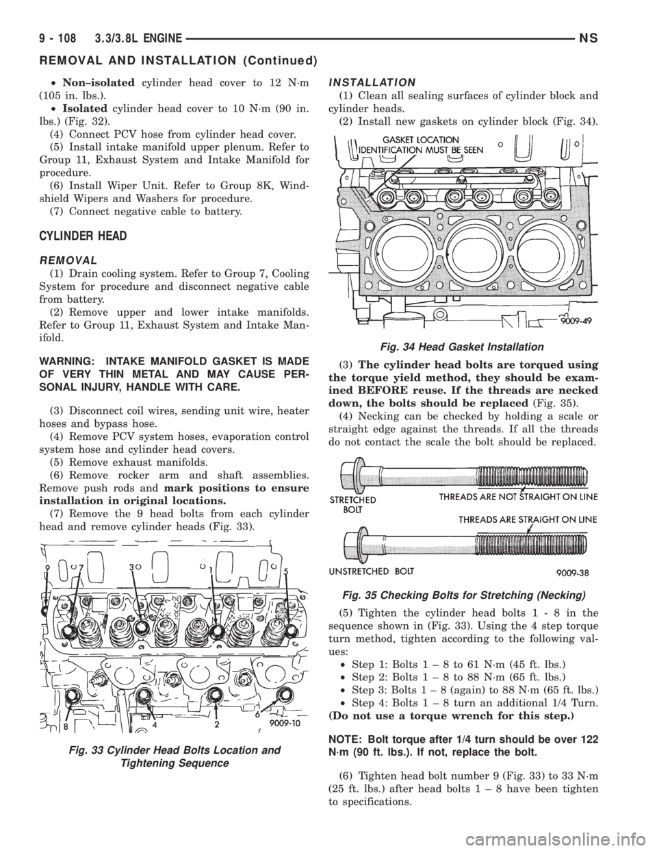
head and remove cylinder heads (Fig. 33).
INSTALLATION
(1) Clean all sealing surfaces of cylinder block and
cylinder heads.
(2) Install new gaskets on cylinder block (Fig. 34).
(3)The cylinder head bolts are torqued using
the torque yield method, they should be exam-
ined BEFORE reuse. If the threads are necked
down, the bolts should be replaced(Fig. 35).
(4) Necking can be checked by holding a scale or
straight edge against the threads. If all the threads
do not contact the scale the bolt should be replaced.
(5) Tighten the cylinder head bolts1-8inthe
sequence shown in (Fig. 33). Using the 4 step torque
turn method, tighten according to the following val-
ues:
²Step 1: Bolts1±8to61N´m(45ft.lbs.)
²Step 2: Bolts1±8to88N´m(65ft.lbs.)
²Step 3: Bolts1±8(again) to 88 N´m (65 ft. lbs.)
²Step 4: Bolts1±8turn an additional 1/4 Turn.
(Do not use a torque wrench for this step.)
NOTE: Bolt torque after 1/4 turn should be over 122
N´m (90 ft. lbs.). If not, replace the bolt.
(6) Tighten head bolt number 9 (Fig. 33) to 33 N´m
(25 ft. lbs.) after head bolts1±8have been tighten
to specifications.
Fig. 33 Cylinder Head Bolts Location and
Tightening Sequence
Fig. 34 Head Gasket Installation
Fig. 35 Checking Bolts for Stretching (Necking)
9 - 108 3.3/3.8L ENGINENS
REMOVAL AND INSTALLATION (Continued)
Page 1163 of 1938
with the dot on the sprocket and install camshaft
sprocket into position.
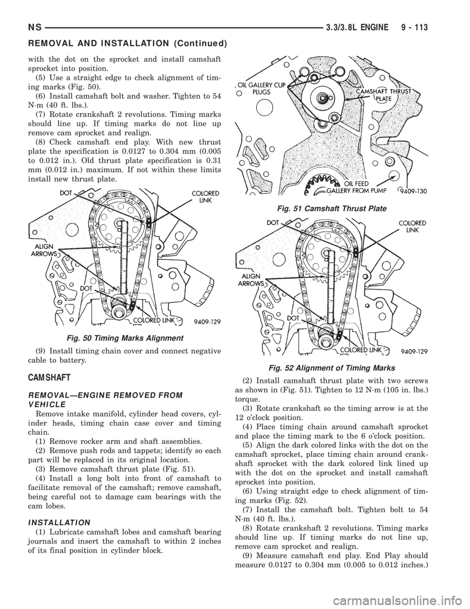
(5) Use a straight edge to check alignment of tim-
ing marks (Fig. 50).
(6) Install camshaft bolt and washer. Tighten to 54
N´m (40 ft. lbs.).
(7) Rotate crankshaft 2 revolutions. Timing marks
should line up. If timing marks do not line up
remove cam sprocket and realign.
(8) Check camshaft end play. With new thrust
plate the specification is 0.0127 to 0.304 mm (0.005
to 0.012 in.). Old thrust plate specification is 0.31
mm (0.012 in.) maximum. If not within these limits
install new thrust plate.
(9) Install timing chain cover and connect negative
cable to battery.
CAMSHAFT
REMOVALÐENGINE REMOVED FROM
VEHICLE
Remove intake manifold, cylinder head covers, cyl-
inder heads, timing chain case cover and timing
chain.
(1) Remove rocker arm and shaft assemblies.
(2) Remove push rods and tappets; identify so each
part will be replaced in its original location.
(3) Remove camshaft thrust plate (Fig. 51).
(4) Install a long bolt into front of camshaft to
facilitate removal of the camshaft; remove camshaft,
being careful not to damage cam bearings with the
cam lobes.
INSTALLATION
(1) Lubricate camshaft lobes and camshaft bearing
journals and insert the camshaft to within 2 inches
of its final position in cylinder block.(2) Install camshaft thrust plate with two screws
as shown in (Fig. 51). Tighten to 12 N´m (105 in. lbs.)
torque.
(3) Rotate crankshaft so the timing arrow is at the
12 o'clock position.
(4) Place timing chain around camshaft sprocket
and place the timing mark to the 6 o'clock position.
(5) Align the dark colored links with the dot on the
camshaft sprocket, place timing chain around crank-
shaft sprocket with the dark colored link lined up
with the dot on the sprocket and install camshaft
sprocket into position.
(6) Using straight edge to check alignment of tim-
ing marks (Fig. 52).
(7) Install the camshaft bolt. Tighten bolt to 54
N´m (40 ft. lbs.).
(8) Rotate crankshaft 2 revolutions. Timing marks
should line up. If timing marks do not line up,
remove cam sprocket and realign.
(9) Measure camshaft end play. End Play should
measure 0.0127 to 0.304 mm (0.005 to 0.012 inches.)
Fig. 50 Timing Marks Alignment
Fig. 51 Camshaft Thrust Plate
Fig. 52 Alignment of Timing Marks
NS3.3/3.8L ENGINE 9 - 113
REMOVAL AND INSTALLATION (Continued)