1996 CHRYSLER VOYAGER battery location
[x] Cancel search: battery locationPage 1203 of 1938
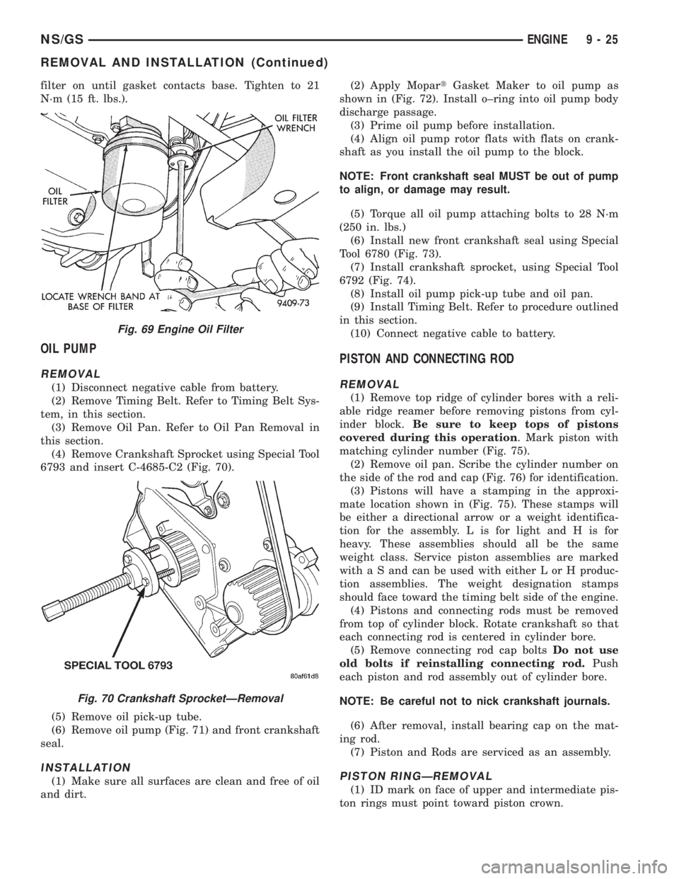
filter on until gasket contacts base. Tighten to 21
N´m (15 ft. lbs.).
OIL PUMP
REMOVAL
(1) Disconnect negative cable from battery.
(2) Remove Timing Belt. Refer to Timing Belt Sys-
tem, in this section.
(3) Remove Oil Pan. Refer to Oil Pan Removal in
this section.
(4) Remove Crankshaft Sprocket using Special Tool
6793 and insert C-4685-C2 (Fig. 70).
(5) Remove oil pick-up tube.
(6) Remove oil pump (Fig. 71) and front crankshaft
seal.
INSTALLATION
(1) Make sure all surfaces are clean and free of oil
and dirt.(2) Apply MopartGasket Maker to oil pump as
shown in (Fig. 72). Install o±ring into oil pump body
discharge passage.
(3) Prime oil pump before installation.
(4) Align oil pump rotor flats with flats on crank-
shaft as you install the oil pump to the block.
NOTE: Front crankshaft seal MUST be out of pump
to align, or damage may result.
(5) Torque all oil pump attaching bolts to 28 N´m
(250 in. lbs.)
(6) Install new front crankshaft seal using Special
Tool 6780 (Fig. 73).
(7) Install crankshaft sprocket, using Special Tool
6792 (Fig. 74).
(8) Install oil pump pick-up tube and oil pan.
(9) Install Timing Belt. Refer to procedure outlined
in this section.
(10) Connect negative cable to battery.
PISTON AND CONNECTING ROD
REMOVAL
(1) Remove top ridge of cylinder bores with a reli-
able ridge reamer before removing pistons from cyl-
inder block.Be sure to keep tops of pistons
covered during this operation. Mark piston with
matching cylinder number (Fig. 75).
(2) Remove oil pan. Scribe the cylinder number on
the side of the rod and cap (Fig. 76) for identification.
(3) Pistons will have a stamping in the approxi-
mate location shown in (Fig. 75). These stamps will
be either a directional arrow or a weight identifica-
tion for the assembly. L is for light and H is for
heavy. These assemblies should all be the same
weight class. Service piston assemblies are marked
with a S and can be used with either L or H produc-
tion assemblies. The weight designation stamps
should face toward the timing belt side of the engine.
(4) Pistons and connecting rods must be removed
from top of cylinder block. Rotate crankshaft so that
each connecting rod is centered in cylinder bore.
(5) Remove connecting rod cap boltsDo not use
old bolts if reinstalling connecting rod.Push
each piston and rod assembly out of cylinder bore.
NOTE: Be careful not to nick crankshaft journals.
(6) After removal, install bearing cap on the mat-
ing rod.
(7) Piston and Rods are serviced as an assembly.
PISTON RINGÐREMOVAL
(1) ID mark on face of upper and intermediate pis-
ton rings must point toward piston crown.
Fig. 69 Engine Oil Filter
Fig. 70 Crankshaft SprocketÐRemoval
NS/GSENGINE 9 - 25
REMOVAL AND INSTALLATION (Continued)
Page 1231 of 1938
ENGINE ASSEMBLY
REMOVAL
(1) Disconnect the battery.
(2) Remove the air cleaner assembly and inlet
hose.
(3) Remove both hoses at intercooler and engine.
(4) Disconnect EGR vacuum hose.
(5) Disconnect brake booster vacuum hose.
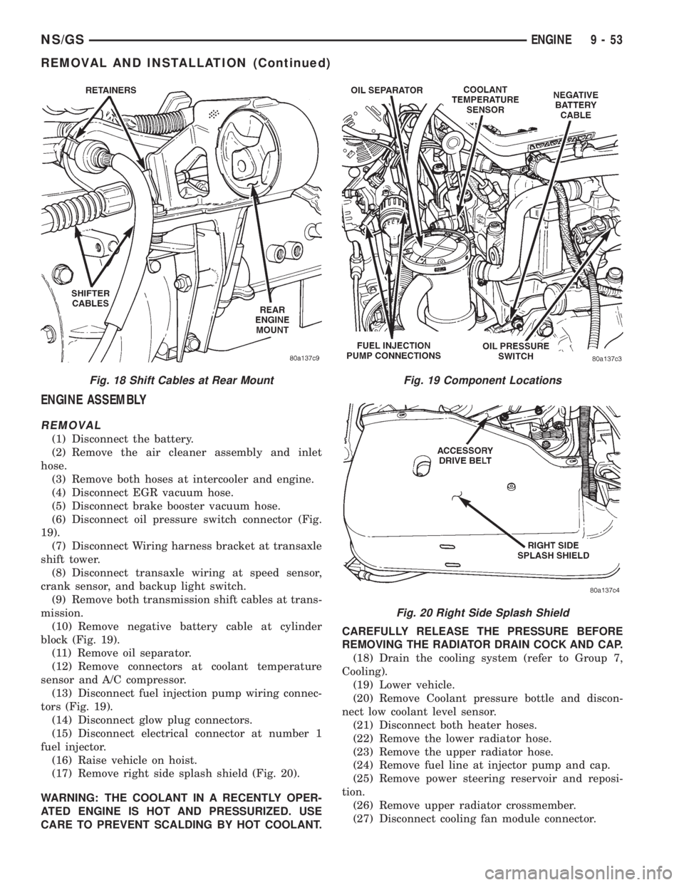
(6) Disconnect oil pressure switch connector (Fig.
19).
(7) Disconnect Wiring harness bracket at transaxle
shift tower.
(8) Disconnect transaxle wiring at speed sensor,
crank sensor, and backup light switch.
(9) Remove both transmission shift cables at trans-
mission.
(10) Remove negative battery cable at cylinder
block (Fig. 19).
(11) Remove oil separator.
(12) Remove connectors at coolant temperature
sensor and A/C compressor.
(13) Disconnect fuel injection pump wiring connec-
tors (Fig. 19).
(14) Disconnect glow plug connectors.
(15) Disconnect electrical connector at number 1
fuel injector.
(16) Raise vehicle on hoist.
(17) Remove right side splash shield (Fig. 20).
WARNING: THE COOLANT IN A RECENTLY OPER-
ATED ENGINE IS HOT AND PRESSURIZED. USE
CARE TO PREVENT SCALDING BY HOT COOLANT.CAREFULLY RELEASE THE PRESSURE BEFORE
REMOVING THE RADIATOR DRAIN COCK AND CAP.
(18) Drain the cooling system (refer to Group 7,
Cooling).
(19) Lower vehicle.
(20) Remove Coolant pressure bottle and discon-
nect low coolant level sensor.
(21) Disconnect both heater hoses.
(22) Remove the lower radiator hose.
(23) Remove the upper radiator hose.
(24) Remove fuel line at injector pump and cap.
(25) Remove power steering reservoir and reposi-
tion.
(26) Remove upper radiator crossmember.
(27) Disconnect cooling fan module connector.
Fig. 18 Shift Cables at Rear MountFig. 19 Component Locations
Fig. 20 Right Side Splash Shield
NS/GSENGINE 9 - 53
REMOVAL AND INSTALLATION (Continued)
Page 1233 of 1938
(3) Install cylinder head cover, torque nuts to 14.7
N´m (132 in. lbs.).
(4) Install coolant pressure tank.
(5) Install breather hose.
(6) Install generator bracket, tighten bolts to 7
N´m (4 ft. lbs.).
(7) Connect the service valves to the A/C compres-
sor ports, if equipped with air conditioning.
(8) Connect battery cable.
VALVE SPRINGSÐCYLINDER HEAD NOT
REMOVED
This procedure can be done with the engine cylin-
der head installed on the block.
REMOVAL
Each valve spring is held in place by a retainer
and a set of conical valve locks. The locks can be
removed only by compressing the valve spring.
(1) Remove the engine cylinder head cover, refer to
cylinder head cover removal in this section.
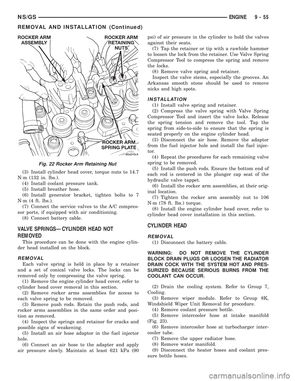
(2) Remove rocker arms assemblies for access to
each valve spring to be removed.
(3) Remove push rods. Retain the push rods, and
rocker arms assemblies in the same order and posi-
tion as removed.
(4) Inspect the springs and retainer for cracks and
possible signs of weakening.
(5) Install an air hose adaptor in the fuel injector
hole.
(6) Connect an air hose to the adapter and apply
air pressure slowly. Maintain at least 621 kPa (90psi) of air pressure in the cylinder to hold the valves
against their seats.
(7) Tap the retainer or tip with a rawhide hammer
to loosen the lock from the retainer. Use Valve Spring
Compressor Tool to compress the spring and remove
the locks.
(8) Remove valve spring and retainer.
Inspect the valve stems, especially the grooves. An
Arkansas smooth stone should be used to remove
nicks and high spots.
INSTALLATION
(1) Install valve spring and retainer.
(2) Compress the valve spring with Valve Spring
Compressor Tool and insert the valve locks. Release
the spring tension and remove the tool. Tap the
spring from side-to-side to ensure that the spring is
seated properly on the engine cylinder head.
(3) Disconnect the air hose. Remove the adaptor
from the fuel injector hole and install the fuel injec-
tor.
(4) Repeat the procedures for each remaining valve
spring to be removed.
(5) Install the push rods. Ensure the bottom end of
each rod is centered in the plunger cap seat of the
hydraulic valve tappet.
(6) Install the rocker arm assemblies, at their orig-
inal location.
(7) Tighten the rocker arm assembly nut to 106
N´m (78 ft. lbs.) torque.
(8) Install the engine cylinder head cover, refer to
cylinder head cover installation in this section.
CYLINDER HEAD
REMOVAL
(1) Disconnect the battery cable.
WARNING: DO NOT REMOVE THE CYLINDER
BLOCK DRAIN PLUGS OR LOOSEN THE RADIATOR
DRAIN COCK WITH THE SYSTEM HOT AND PRES-
SURIZED BECAUSE SERIOUS BURNS FROM THE
COOLANT CAN OCCUR.
(2) Drain the cooling system. Refer to Group 7,
Cooling.
(3) Remove wiper module. Refer to Group 8K,
Windshield Wiper Unit Removal for procedure.
(4) Remove coolant pressure bottle.
(5) Remove intercooler hose at intake manifold
(Fig. 23).
(6) Remove intercooler hose at turbocharger inter-
cooler tube.
(7) Remove the upper radiator hose.
(8) Remove water manifold.
(9) Disconnect the heater hoses and coolant pres-
sure bottle hoses.
Fig. 22 Rocker Arm Retaining Nut
NS/GSENGINE 9 - 55
REMOVAL AND INSTALLATION (Continued)
Page 1240 of 1938
(7) Remove power steering/air conditioning pulley
nut. Remove pulley.
CAUTION: Remove old loctite from threads on
pump.
(8) Remove pump shaft support bracket assembly.
(9) Disconnect the water drain pipe hose at the
timing cover.
CAUTION: When separating the timing geat cover
from the block take care not to damage the mating
surface of the timing gear cover or block. Also take
care not to damage the timing gears or components
located inside the timing gear cover near the edge.
(10) Remove timing gear cover.
INSTALLATION
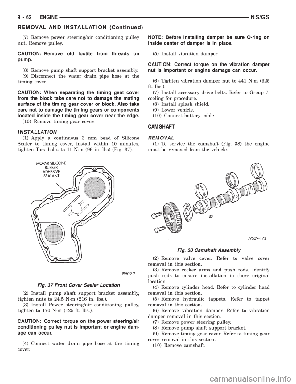
(1) Apply a continuous 3 mm bead of Silicone
Sealer to timing cover, install within 10 minutes,
tighten Torx bolts to 11 N´m (96 in. lbs) (Fig. 37).
(2) Install pump shaft support bracket assembly,
tighten nuts to 24.5 N´m (216 in. lbs.).
(3) Install Power steering/air conditioning pulley,
tighten to 170 N´m (125 ft. lbs.).
CAUTION: Correct torque on the power steering/air
conditioning pulley nut is important or engine dam-
age can occur.
(4) Connect water drain pipe hose at the timing
cover.NOTE: Before installing damper be sure O-ring on
inside center of damper is in place.
(5) Install vibration damper.
CAUTION: Correct torque on the vibration damper
nut is important or engine damage can occur.
(6) Tighten vibration damper nut to 441 N´m (325
ft. lbs.).
(7) Install accessary drive belts. Refer to Group 7,
cooling for procedure.
(8) Install splash shield.
(9) Lower vehicle.
(10) Connect battery cable.
CAMSHAFT
REMOVAL
(1) To service the camshaft (Fig. 38) the engine
must be removed from the vehicle.
(2) Remove valve cover. Refer to valve cover
removal in this section.
(3) Remove rocker arms and push rods. Identify
push rods to ensure installation in there original
location.
(4) Remove cylinder head. Refer to cylinder head
removal in this section.
(5) Remove hydraulic tappets. Refer to tappet
removal in this section.
(6) Remove vibration damper. Refer to vibration
damper removal in this section.
(7) Remove power steering pulley.
(8) Remove pump shaft support bracket.
(9) Remove timing gear cover. Refer to timing gear
cover removal in this section.
(10) Remove camshaft.
Fig. 37 Front Cover Sealer Location
Fig. 38 Camshaft Assembly
9 - 62 ENGINENS/GS
REMOVAL AND INSTALLATION (Continued)
Page 1241 of 1938
THRUST PLATE INSPECTION
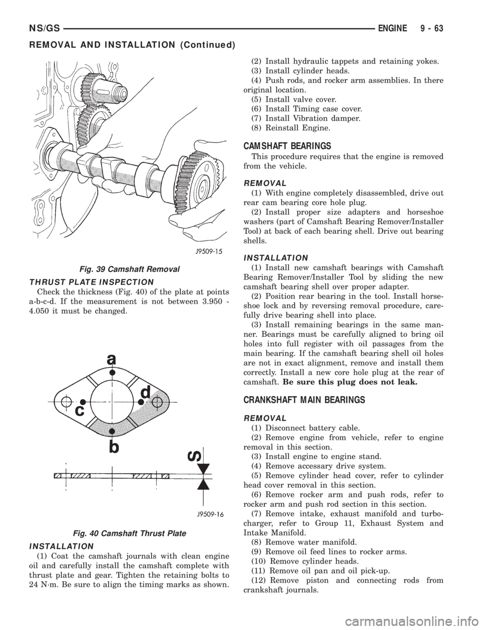
Check the thickness (Fig. 40) of the plate at points
a-b-c-d. If the measurement is not between 3.950 -
4.050 it must be changed.
INSTALLATION
(1) Coat the camshaft journals with clean engine
oil and carefully install the camshaft complete with
thrust plate and gear. Tighten the retaining bolts to
24 N´m. Be sure to align the timing marks as shown.(2) Install hydraulic tappets and retaining yokes.
(3) Install cylinder heads.
(4) Push rods, and rocker arm assemblies. In there
original location.
(5) Install valve cover.
(6) Install Timing case cover.
(7) Install Vibration damper.
(8) Reinstall Engine.
CAMSHAFT BEARINGS
This procedure requires that the engine is removed
from the vehicle.
REMOVAL
(1) With engine completely disassembled, drive out
rear cam bearing core hole plug.
(2) Install proper size adapters and horseshoe
washers (part of Camshaft Bearing Remover/Installer
Tool) at back of each bearing shell. Drive out bearing
shells.
INSTALLATION
(1) Install new camshaft bearings with Camshaft
Bearing Remover/Installer Tool by sliding the new
camshaft bearing shell over proper adapter.
(2) Position rear bearing in the tool. Install horse-
shoe lock and by reversing removal procedure, care-
fully drive bearing shell into place.
(3) Install remaining bearings in the same man-
ner. Bearings must be carefully aligned to bring oil
holes into full register with oil passages from the
main bearing. If the camshaft bearing shell oil holes
are not in exact alignment, remove and install them
correctly. Install a new core hole plug at the rear of
camshaft.Be sure this plug does not leak.
CRANKSHAFT MAIN BEARINGS
REMOVAL
(1) Disconnect battery cable.
(2) Remove engine from vehicle, refer to engine
removal in this section.
(3) Install engine to engine stand.
(4) Remove accessary drive system.
(5) Remove cylinder head cover, refer to cylinder
head cover removal in this section.
(6) Remove rocker arm and push rods, refer to
rocker arm and push rod section in this section.
(7) Remove intake, exhaust manifold and turbo-
charger, refer to Group 11, Exhaust System and
Intake Manifold.
(8) Remove water manifold.
(9) Remove oil feed lines to rocker arms.
(10) Remove cylinder heads.
(11) Remove oil pan and oil pick-up.
(12) Remove piston and connecting rods from
crankshaft journals.
Fig. 39 Camshaft Removal
Fig. 40 Camshaft Thrust Plate
NS/GSENGINE 9 - 63
REMOVAL AND INSTALLATION (Continued)
Page 1283 of 1938
FRAME
INDEX
page page
REMOVAL AND INSTALLATION
FRONT CROSSMEMBER MOUNT BUSHINGS . . . 5
FRONT CROSSMEMBER................... 3SPECIFICATIONS
FRAME AND BODY OPENING DIMENSIONS.... 5
REMOVAL AND INSTALLATION
FRONT CROSSMEMBER
The front suspension crossmember must be
installed in the design location to achieve proper
front end suspension alignment. If the crossmember
is removed without applying reference marks on the
frame rails, align the crossmember according to the
dimensions provided in this group.
NOTE: If the caged nuts in the frame rails become
damaged and cannot be reused, a replacement nut
can be obtained through a MoparTParts supplier.
REMOVAL
(1) Disconnect battery negative cable.
(2) Remove steering column lower cover from
instrument panel. Refer to Group 8E, Instrument
Panel and Systems.
(3) Remove knee blocker reinforcement. Refer to
Group 8E, Instrument Panel and Systems.
(4) Position steering so front wheels are straight
ahead.
CAUTION: Do not rotate steering wheel after disen-
gaging lower coupling from steering gear, damage
to airbag clock spring can result.
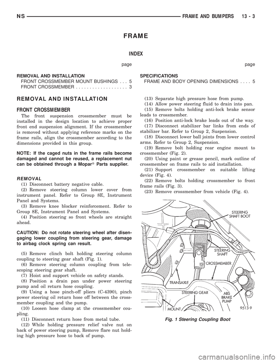
(5) Remove clinch bolt holding steering column
coupling to steering gear shaft (Fig. 1).
(6) Remove steering column coupling from tele-
scoping steering gear shaft.
(7) Hoist and support vehicle on safety stands.
(8) Position a drain pan under power steering
pump and oil return hose coupling.
(9) Using a hose pinch-off pliers (C-4390), pinch
power steering oil return hose off between the cross-
member coupling and the pump.
(10) Loosen hose clamp at the crossmember cou-
pling.
(11) Disconnect return hose from metal tube.
(12) While holding pressure relief valve nut on
back of power steering pump, Remove flare nut hold-
ing high pressure hose to back of pump.(13) Separate high pressure hose from pump.
(14) Allow power steering fluid to drain into pan.
(15) Remove bolts holding anti-lock brake sensor
leads to crossmember.
(16) Position anti-lock brake leads out of the way.
(17) Disconnect stabilizer bar links from ends of
stabilizer bar. Refer to Group 2, Suspension.
(18) Disconnect lower ball joints from lower control
arms. Refer to Group 2, Suspension.
(19) Remove bolt holding rear engine mount to
crossmember (Fig. 2).
(20) Using paint or grease pencil, mark outline of
crossmember on frame rails to aid installation.
(21) Support crossmember on suitable lifting
device (Fig. 4).
(22) Remove bolts holding crossmember to front
frame rails (Fig. 3).
(23) Remove crossmember from vehicle (Fig. 4).
Fig. 1 Steering Coupling Boot
NSFRAME AND BUMPERS 13 - 3
Page 1285 of 1938
(7) Connect lower ball joints to lower control arms.
Refer to Group 2, Suspension.
(8) Connect stabilizer bar links to ends of stabi-
lizer bar. Refer to Group 2, Suspension.
(9) Install bolts to hold anti-lock brake sensor
leads to crossmember.
(10) Install high pressure hose to pump.
(11) Connect return hose to metal tube.
(12) Tighten hose clamp at the crossmember cou-
pling.
(13) Remove pinch-off pliers.
(14) Position steering so front wheels are straight
ahead.
(15) Install steering column coupling to telescoping
steering gear shaft.
(16) Install clinch bolt to hold steering column cou-
pling to steering gear shaft.
(17) Install knee blocker reinforcement. Refer to
Group 8E, Instrument Panel and Systems.
(18) Install steering column lower cover from
instrument panel. Refer to Group 8E, Instrument
Panel and Systems.
(19) Connect battery negative cable.
FRONT CROSSMEMBER MOUNT BUSHINGS
REMOVAL
(1) Using paint or grease pencil, mark outline of
crossmember on frame rails.
(2) Loosen bolts holding crossmember to frame
rails.
(3) Remove bolt on bushing that requires replace-
ment.
(4) Allow crossmember to drop down enough to
gain clearance for bushing removal.
(5) Remove bushing from vehicle.
INSTALLATION
(1) Apply rubber lube or soap to replacement bush-
ing.(2) Insert lower half of bushing into square hole in
crossmember.
(3) Place upper half of bushing on top of cross-
member aligned to receive square tube protruding
upward from lower bushing half.
(4) Squeeze bushing halves together to ensure they
are properly mated.
(5) Lift crossmember upward to close gap between
the bushing and frame.
(6) Verify that lower bushing is fully seated into
crossmember and upper bushing.
(7) Install bolt to hold bushing and crossmember
to frame rail hand tight.
(8) Align crossmember to reference marks on
frame rails.
(9) Tighten crossmember to frame rails attaching
bolts to 163 N´m (120 ft. lbs.) torque.
SPECIFICATIONS
FRAME AND BODY OPENING DIMENSIONS
Frame dimensions are listed in metric scale. All
dimensions are from center to center of Principal
Locating Point (PLP), or from center to center of PLP
and fastener location.
VEHICLE PREPARATION
Position the vehicle on a frame alignment rack,
refer to instructions provided with equipment being
used. Adjust the vehicle PLP heights to the specified
dimension above the work surface (datum line). Ver-
tical dimensions can be taken from the datum line to
the locations indicated were applicable. Refer to (Fig.
5), (Fig. 6), (Fig. 7), (Fig. 8), (Fig. 9), (Fig. 10) and
(Fig. 11) for proper dimensions.
NSFRAME AND BUMPERS 13 - 5
REMOVAL AND INSTALLATION (Continued)
Page 1305 of 1938
SERVICE PROCEDURES
FUEL SYSTEM PRESSURE RELEASE
PROCEDUREÐ2.4/3.3/3.8L
WARNING: RELEASE FUEL SYSTEM PRESSURE
BEFORE SERVICING FUEL SYSTEM COMPONENTS.
SERVICE VEHICLES IN WELL VENTILATED AREAS
AND AVOID IGNITION SOURCES. NEVER SMOKE
WHILE SERVICING THE VEHICLE.
(1) Disconnect negative cable from battery.
(2) Remove fuel filler cap.
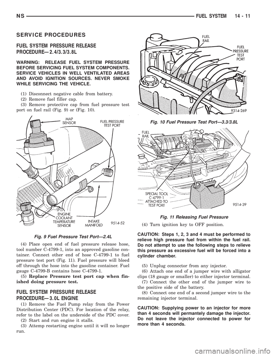
(3) Remove protective cap from fuel pressure test
port on fuel rail (Fig. 9) or (Fig. 10).
(4) Place open end of fuel pressure release hose,
tool number C-4799-1, into an approved gasoline con-
tainer. Connect other end of hose C-4799-1 to fuel
pressure test port (Fig. 11). Fuel pressure will bleed
off through the hose into the gasoline container. Fuel
gauge C-4799-B contains hose C-4799-1.
(5)Replace Pressure test port cap when fin-
ished doing pressure test.
FUEL SYSTEM PRESSURE RELEASE
PROCEDUREÐ3.0L ENGINE
(1) Remove the Fuel Pump relay from the Power
Distribution Center (PDC). For location of the relay,
refer to the label on the underside of the PDC cover.
(2) Start and run engine it stalls.
(3) Attemp restarting engine until it will no longer
run.(4) Turn ignition key to OFF position.
CAUTION: Steps 1, 2, 3 and 4 must be performed to
relieve high pressure fuel from within the fuel rail.
Do not attempt to use the following steps to relieve
this pressure as excessive fuel will be forced into a
cylinder chamber.
(5) Unplug connector from any injector.
(6) Attach one end of a jumper wire with alligator
clips (18 gauge or smaller) to either injector terminal.
(7) Connect the other end of the jumper wire to
the positive side of the battery.
(8) Connect one end of a second jumper wire to the
remaining injector terminal.
CAUTION: Supplying power to an injector for more
than 4 seconds will permantely damage the injector.
Do not leave the injector connected to power for
more than 4 seconds.
Fig. 9 Fuel Pressure Test PortÐ2.4L
Fig. 10 Fuel Pressure Test PortÐ3.3/3.8L
Fig. 11 Releasing Fuel Pressure
NSFUEL SYSTEM 14 - 11