1996 CHRYSLER VOYAGER battery
[x] Cancel search: batteryPage 1661 of 1938
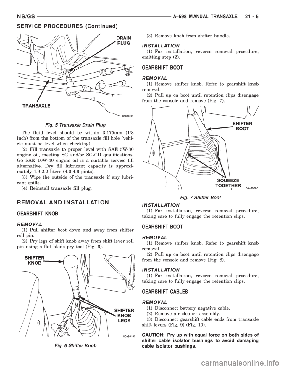
The fluid level should be within 3.175mm (1/8
inch) from the bottom of the transaxle fill hole (vehi-
cle must be level when checking).
(2) Fill transaxle to proper level with SAE 5W-30
engine oil, meeting SG and/or SG-CD qualifications.
G5 SAE 10W-40 engine oil is a suitable service fill
alternative. Dry fill lubricant capacity is approxi-
mately 1.9-2.2 liters (4.0-4.6 pints).
(3) Wipe the outside of the transaxle if any lubri-
cant spills.
(4) Reinstall transaxle fill plug.
REMOVAL AND INSTALLATION
GEARSHIFT KNOB
REMOVAL
(1) Pull shifter boot down and away from shifter
roll pin.
(2) Pry legs of shift knob away from shift lever roll
pin using a flat blade pry tool (Fig. 6).(3) Remove knob from shifter handle.
INSTALLATION
(1) For installation, reverse removal procedure,
omitting step (2).
GEARSHIFT BOOT
REMOVAL
(1) Remove shifter knob. Refer to gearshift knob
removal.
(2) Pull up on boot until retention clips disengage
from the console and remove (Fig. 7).
INSTALLATION
(1) For installation, reverse removal procedure,
taking care to fully engage the retention clips.
GEARSHIFT BOOT
REMOVAL
(1) Remove shifter knob. Refer to gearshift knob
removal.
(2) Pull up on boot until retention clips disengage
from the console and remove (Fig. 8).
INSTALLATION
(1) For installation, reverse removal procedure,
taking care to fully engage the retention clips.
GEARSHIFT CABLES
REMOVAL
(1) Disconnect battery negative cable.
(2) Remove air cleaner assembly.
(3) Disconnect gearshift cable ends from transaxle
shift levers (Fig. 9) (Fig. 10).
CAUTION: Pry up with equal force on both sides of
shifter cable isolator bushings to avoid damaging
cable isolator bushings.
Fig. 5 Transaxle Drain Plug
Fig. 6 Shifter Knob
Fig. 7 Shifter Boot
NS/GSA±598 MANUAL TRANSAXLE 21 - 5
SERVICE PROCEDURES (Continued)
Page 1663 of 1938
INSTALLATION
(1) To install, reverse removal procedure. After
cables have been replaced, cable adjustment should
be checked. Refer to cable adjustment procedure in
this section.
NOTE: High temperature tie straps must be used
when replacing cable(s). Locate the new tie strap at
the white band on the crossover cable and cinch
cables tightly together.
CAUTION: Only the crossover cable is adjustable.
The selector cable does not have any adjustment
capabilities.
GEARSHIFT CABLESÐRHD VEHICLES
REMOVAL
(1) Disconnect battery negative cable.
(2) Remove air cleaner assembly.(3) Disconnect gearshift cable ends from transaxle
shift levers (Fig. 16) (Fig. 17).
CAUTION: Pry up with equal force on both sides of
shifter cable isolator bushings to avoid damaging
cable isolator bushings.
(4) Remove cable to bracket retaining clips at tran-
saxle (Fig. 18).
CAUTION: It is recommended that new cable retain-
ing clips be used for reinstallation.
(5) Pull cables up out of engine mount bracket.
(6) Remove gearshift knob and boot. Refer to Knob
and Boot Removal in this section.
(7) Remove console screws (Fig. 19).
(8) Remove cable retaining clips at shifter (Fig. 20)
(Fig. 21).
CAUTION: It is recommended that new cable retain-
ing clips be used for reinstallation. Clips must be
installed to span the slotted holes.
(9) Disconnect shift cables from shifter. Pry with
equal force on both sides of shifter cable isolator
bushings to avoid damaging bushings.
(10) Lift vehicle on hoist. Cut gearshift cable tie
strap at floor pan with diagonal cutters.
(11) Remove shift cables from vehicle by grasping
cables and grommets one at a time and tugging down
through floor pan holes (Fig. 22).
INSTALLATION
(1) To install, reverse removal procedure. After
cables have been replaced, cable adjustment should
be checked. Refer to cable adjustment procedure in
this section.
NOTE: High temperature tie straps must be used
when replacing cable(s). Locate the new tie strap at
the white band on the crossover cable and cinch
cables tightly together.
CAUTION: Only the crossover cable is adjustable.
The selector cable does not have any adjustment
capabilities.
GEARSHIFT MECHANISM REPLACEMENT
REMOVAL
(1) Remove shifter knob and boot. refer to Shifter
Knob And Boot Removal procedure in this section.
(2) Remove console assembly. Refer to Console
Removal procedure in this section.
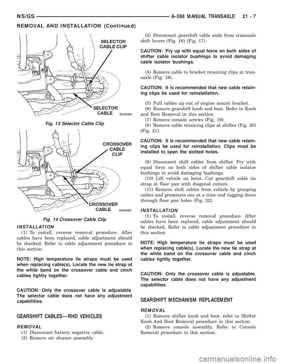
Fig. 13 Selector Cable Clip
Fig. 14 Crossover Cable Clip
NS/GSA±598 MANUAL TRANSAXLE 21 - 7
REMOVAL AND INSTALLATION (Continued)
Page 1668 of 1938
DIFFERENTIAL BEARING RETAINER AXLE
SEAL
REMOVAL
(1) Remove axle shaft. Refer to Group 2, Suspen-
sion and Driveshafts for service procedures.
(2) Insert a flat±blade pry tool into the axle seal
bore.
(3) Using the pry tool, carefully pop out the seal
taking care not to nick the seal bore.
INSTALLATION
(1) Clean axle shaft seal bore of any excess seal-
ant.
(2) Align axle shaft seal with axle shaft seal bore.
(3) Position axle seal at extension housing.
(4) Using Tool L-4520 and Tool C-4171, tap seal
into position.
SHIFT SHAFT SEALS
It isnotnecessary to remove the shift shaft cover
from the transaxle to service the shift shaft seals.
REMOVAL
(1) Remove the shift lever from the seal that is to
be serviced. Refer to shift lever removal for service
procedure.
(2) Using a pick tool, pry up on the shift shaft seal
and remove seal from bore.
INSTALLATION
(1) Position new shift shaft seal in bore.
(2) Install shift shaft seal into bore using an
appropriate size deep±well socket.
TRANSAXLE
The following items can be serviced without remov-
ing the transaxle from the vehicle:
²Gearshift housing
²5th speed synchronizer
²5th speed gear
²Roller detents and springs
²Speedometer pinion
²Vehicle speed sensor
²Bearing retainer plate.
²All external covers
²Shift shaft seals
²Axle shaft seals
To service any other component of the A-598 tran-
saxle you must remove it from the vehicle.
REMOVAL
(1) Disconnect battery negative cable.
(2) Remove air intake hose. Disconnect air mass
meter connector.
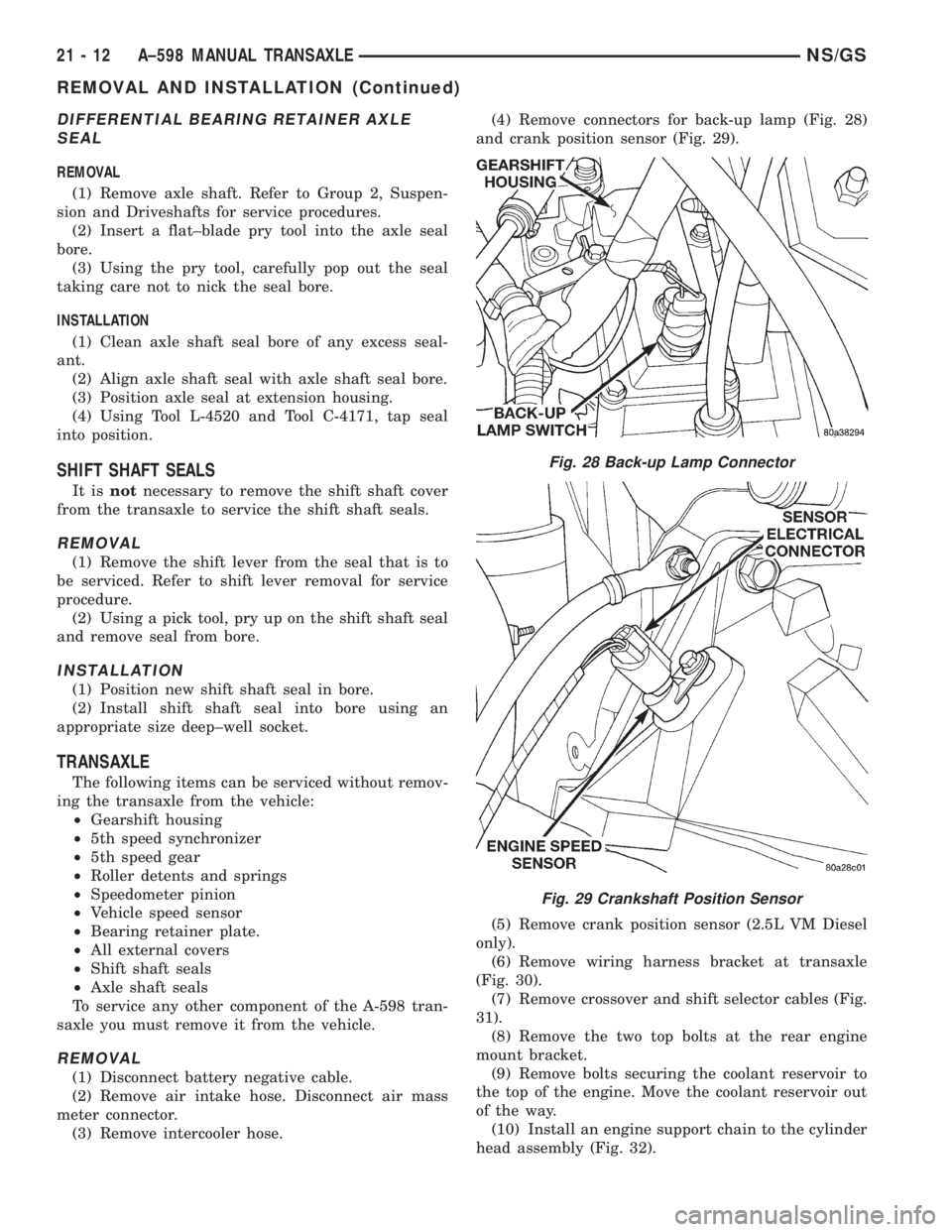
(3) Remove intercooler hose.(4) Remove connectors for back-up lamp (Fig. 28)
and crank position sensor (Fig. 29).
(5) Remove crank position sensor (2.5L VM Diesel
only).
(6) Remove wiring harness bracket at transaxle
(Fig. 30).
(7) Remove crossover and shift selector cables (Fig.
31).
(8) Remove the two top bolts at the rear engine
mount bracket.
(9) Remove bolts securing the coolant reservoir to
the top of the engine. Move the coolant reservoir out
of the way.
(10) Install an engine support chain to the cylinder
head assembly (Fig. 32).
Fig. 28 Back-up Lamp Connector
Fig. 29 Crankshaft Position Sensor
21 - 12 A±598 MANUAL TRANSAXLENS/GS
REMOVAL AND INSTALLATION (Continued)
Page 1672 of 1938
(2) Tighten the input bearing retainer sleeve bolts
to 28 N´m (250 in. lbs.).
INPUT SHAFT SEAL
REMOVAL
(1) Remove input shaft front bearing retainer from
transaxle case. Refer to Input Bearing Retainer
Removal in this group.
(2) Place the retainer in a soft-jawed vise.
(3) Using a flat-blade pry tool, remove the input
shaft seal from the retainer.
INSTALLATION
(1) Position the new input shaft seal in the
retainer.
(2) Place the retainer on a flat surface (seal side
down).
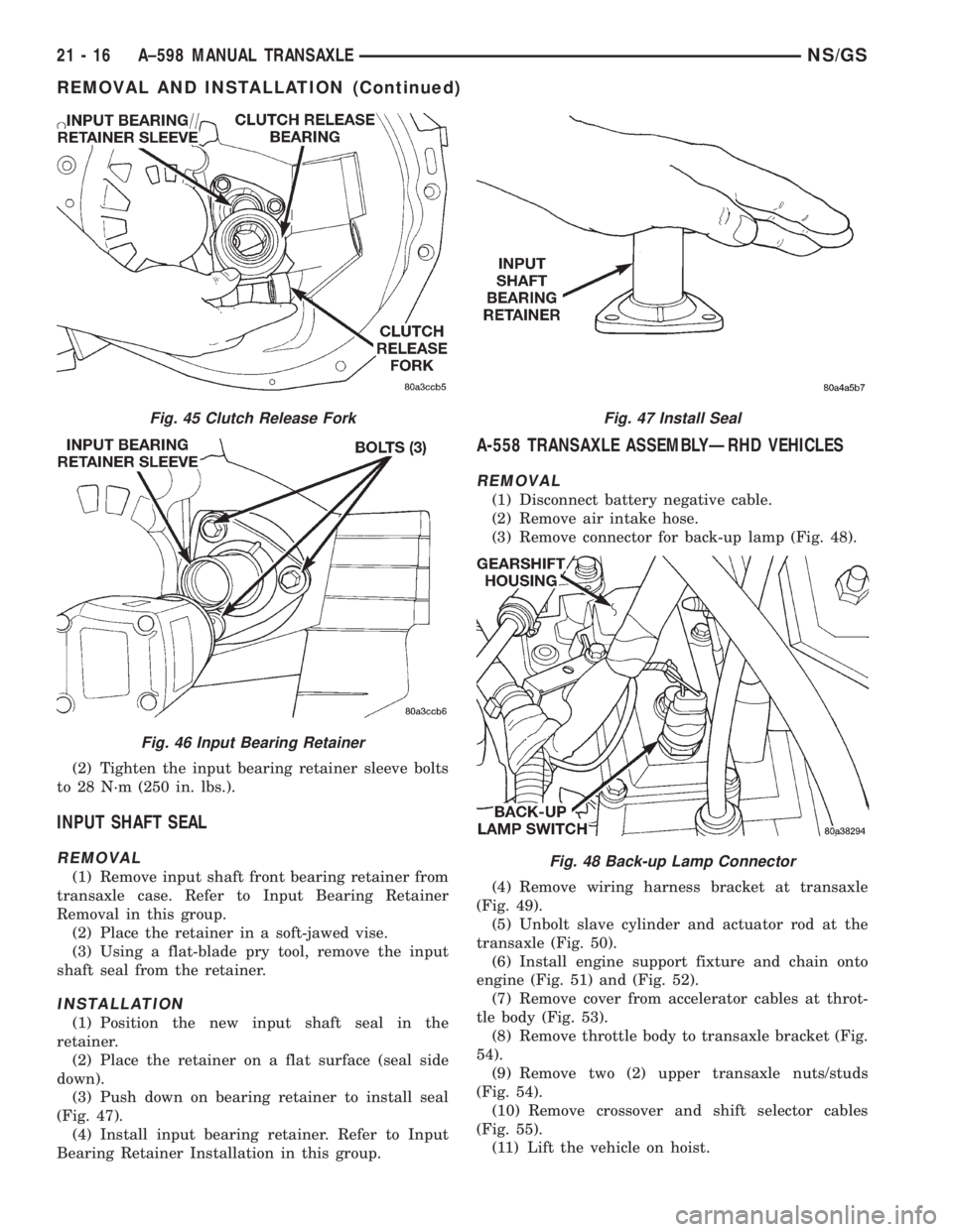
(3) Push down on bearing retainer to install seal
(Fig. 47).
(4) Install input bearing retainer. Refer to Input
Bearing Retainer Installation in this group.
A-558 TRANSAXLE ASSEMBLYÐRHD VEHICLES
REMOVAL
(1) Disconnect battery negative cable.
(2) Remove air intake hose.
(3) Remove connector for back-up lamp (Fig. 48).
(4) Remove wiring harness bracket at transaxle
(Fig. 49).
(5) Unbolt slave cylinder and actuator rod at the
transaxle (Fig. 50).
(6) Install engine support fixture and chain onto
engine (Fig. 51) and (Fig. 52).
(7) Remove cover from accelerator cables at throt-
tle body (Fig. 53).
(8) Remove throttle body to transaxle bracket (Fig.
54).
(9) Remove two (2) upper transaxle nuts/studs
(Fig. 54).
(10) Remove crossover and shift selector cables
(Fig. 55).
(11) Lift the vehicle on hoist.
Fig. 45 Clutch Release Fork
Fig. 46 Input Bearing Retainer
Fig. 47 Install Seal
Fig. 48 Back-up Lamp Connector
21 - 16 A±598 MANUAL TRANSAXLENS/GS
REMOVAL AND INSTALLATION (Continued)
Page 1731 of 1938
BODY
CONTENTS
page page
BODY COMPONENT SERVICE.............. 22
GENERAL SERVICE INFORMATION........... 1
PAINT.................................. 2SEATS .................................. 9
STATIONARY GLASS....................... 4
GENERAL SERVICE INFORMATION
INDEX
page
GENERAL INFORMATION
SAFETY PRECAUTIONS AND WARNINGS...... 1
GENERAL INFORMATION
SAFETY PRECAUTIONS AND WARNINGS
WARNING: EYE PROTECTION SHOULD BE USED
WHEN SERVICING GLASS COMPONENTS. PER-
SONAL INJURY CAN RESULT.
USE A OSHA APPROVED BREATHING FILTER
WHEN SPRAYING PAINT OR SOLVENTS IN A CON-
FINED AREA. PERSONAL INJURY CAN RESULT.
AVOID PROLONGED SKIN CONTACT WITH
PETROLEUM OR ALCOHOL± BASED CLEANING
SOLVENTS. PERSONAL INJURY CAN RESULT.
DO NOT STAND UNDER A HOISTED VEHICLE
THAT IS NOT PROPERLY SUPPORTED ON SAFETY
STANDS. PERSONAL INJURY CAN RESULT.
CAUTION: When holes must be drilled or punched
in an inner body panel, verify depth of space to the
outer body panel, electrical wiring, or other compo-
nents. Damage to vehicle can result.
Do not weld exterior panels unless combustible
material on the interior of vehicle is removed from
the repair area. Fire or hazardous conditions, can
result.
Always have a fire extinguisher ready for use
when welding.
Disconnect the negative (-) cable clamp from the
battery when servicing electrical components that
are live when the ignition is OFF. Damage to electri-
cal system can result.Do not use abrasive chemicals or compounds on
painted surfaces. Damage to finish can result.
Do not use harsh alkaline based cleaning sol-
vents on painted or upholstered surfaces. Damage
to finish or color can result.
Do not hammer or pound on plastic trim panel
when servicing interior trim. Plastic panels can
break.
Chrysler Corporation uses many different types of
push-in fasteners to secure the interior and exterior
trim to the body. Most of these fasteners can be
reused to assemble the trim during various repair
procedures. At times, a push-in fastener cannot be
removed without damaging the fastener or the com-
ponent it is holding. If it is not possible to remove a
fastener without damaging a component or body, cut
or break the fastener and use a new one when
installing the component. Never pry or pound on a
plastic or pressed-board trim component. Using a
suitable fork-type prying device, pry the fastener
from the retaining hole behind the component being
removed. When installing, verify fastener alignment
with the retaining hole by hand. Push directly on or
over the fastener until it seats. Apply a low-force pull
to the panel to verify that it is secure.
When it is necessary to remove components to ser-
vice another, it should not be necessary to apply
excessive force or bend a component to remove it.
Before damaging a trim component, verify hidden
fasteners or captured edges holding the component in
place.
NSBODY 23 - 1
Page 1754 of 1938
Some water leaks must be tested for a considerable
length of time to become apparent. When a leak
appears, find the highest point of the water track or
drop. The highest point usually will show the point of
entry. After leak point has been found, repair the
leak and water test to verify that the leak has
stopped.
Locating the entry point of water that is leaking
into a cavity between panels can be difficult. The
trapped water may splash or run from the cavity,
often at a distance from the entry point. Most water
leaks of this type become apparent after accelerating,
stopping, turning, or when on an incline.
MIRROR INSPECTION METHOD
When a leak point area is visually obstructed, use
a suitable mirror to gain visual access. A mirror can
also be used to deflect light to a limited-access area
to assist in locating a leak point.
BRIGHT LIGHT LEAK TEST METHOD
Some water leaks in the luggage compartment can
be detected without water testing. Position the vehi-
cle in a brightly lit area. From inside the darkened
luggage compartment inspect around seals and body
seams. If necessary, have a helper direct a drop light
over the suspected leak areas around the luggage
compartment. If light is visible through a normally
sealed location, water could enter through the open-
ing.
PRESSURIZED LEAK TEST METHOD
When a water leak into the passenger compart-
ment cannot be detected by water testing, pressurize
the passenger compartment and soap test exterior of
the vehicle. To pressurize the passenger compart-
ment, close all doors and windows, start engine, and
set heater control to high blower in HEAT position. If
engine can not be started, connect a charger to the
battery to ensure adequate voltage to the blower.
With interior pressurized, apply dish detergent solu-
tion to suspected leak area on the exterior of the
vehicle. Apply detergent solution with spray device or
soft bristle brush. If soap bubbles occur at a body
seam, joint, seal or gasket, the leak entry point could
be at that location.
WIND NOISE
Wind noise is the result of most air leaks. Air leaks
can be caused by poor sealing, improper body compo-
nent alignment, body seam porosity, or missing plugs
in the engine compartment or door hinge pillar areas.
All body sealing points should be airtight in normal
driving conditions. Moving sealing surfaces will not
always seal airtight under all conditions. At times,
side glass or door seals will allow wind noise to be
noticed in the passenger compartment during highcrosswinds. Over compensating on door or glass
adjustments to stop wind noise that occurs under
severe conditions can cause premature seal wear and
excessive closing or latching effort. After a repair pro-
cedure has been performed, test vehicle to verify
noise has stopped before returning vehicle to use.
Wind noise can also be caused by improperly fitted
exterior moldings or body ornamentation. Loose
moldings can flutter, creating a buzzing or chattering
noise. An open cavity or protruding edge can create a
whistling or howling noise. Inspect the exterior of the
vehicle to verify that these conditions do not exist.
VISUAL INSPECTION BEFORE TESTS
Verify that floor and body plugs are in place and
body components are aligned and sealed. If component
alignment or sealing is necessary, refer to the appro-
priate section of this group for proper procedures.
ROAD TESTING WIND NOISE
(1) Drive the vehicle to verify the general location
of the wind noise.
(2) Apply 50 mm (2 in.) masking tape in 150 mm
(6 in.) lengths along weatherstrips, weld seams or
moldings. After each length is applied, drive the vehi-
cle. If noise goes away after a piece of tape is applied,
remove tape, locate, and repair defect.
POSSIBLE CAUSE OF WIND NOISE
²Moldings standing away from body surface can
catch wind and whistle.
²Gaps in sealed areas behind overhanging body
flanges can cause wind-rushing sounds.
²Misaligned movable components.
²Missing or improperly installed plugs in pillars.
²Weld burn through holes.
SERVICE PROCEDURES
HEAT STAKING
(1) Remove trim panel.
(2) Bend or move the trim panel components at
the heat staked joints. Observe the heat staked loca-
tions and/or component seams for looseness.
(3) Heat stake the components.
(a) If the heat staked or component seam loca-
tion is loose, hold the two components tightly
together and using a soldering gun with a flat tip,
melt the material securing the components
together. Do not over heat the affected area, dam-
age to the exterior of the trim panel may occur.
(b) If the heat staked material is broken or miss-
ing, use a hot glue gun to apply new material to
the area to be repaired. The panels that are being
heat staked must be held together while the apply-
ing the glue. Once the new material is in place, it
23 - 24 BODYNS
DIAGNOSIS AND TESTING (Continued)
Page 1774 of 1938
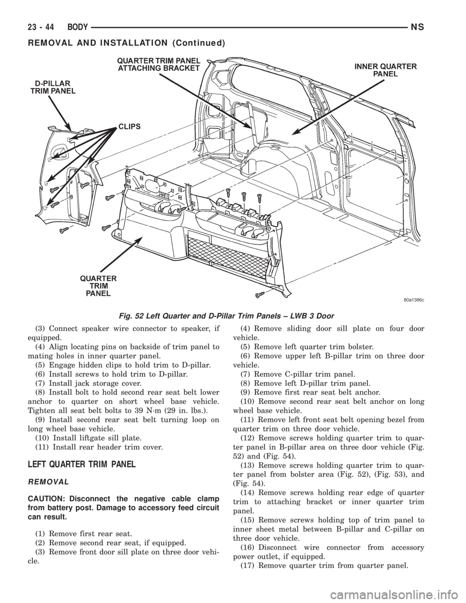
(3) Connect speaker wire connector to speaker, if
equipped.
(4) Align locating pins on backside of trim panel to
mating holes in inner quarter panel.
(5) Engage hidden clips to hold trim to D-pillar.
(6) Install screws to hold trim to D-pillar.
(7) Install jack storage cover.
(8) Install bolt to hold second rear seat belt lower
anchor to quarter on short wheel base vehicle.
Tighten all seat belt bolts to 39 N´m (29 in. lbs.).
(9) Install second rear seat belt turning loop on
long wheel base vehicle.
(10) Install liftgate sill plate.
(11) Install rear header trim cover.
LEFT QUARTER TRIM PANEL
REMOVAL
CAUTION: Disconnect the negative cable clamp
from battery post. Damage to accessory feed circuit
can result.
(1) Remove first rear seat.
(2) Remove second rear seat, if equipped.
(3) Remove front door sill plate on three door vehi-
cle.(4) Remove sliding door sill plate on four door
vehicle.
(5) Remove left quarter trim bolster.
(6) Remove upper left B-pillar trim on three door
vehicle.
(7) Remove C-pillar trim panel.
(8) Remove left D-pillar trim panel.
(9) Remove first rear seat belt anchor.
(10) Remove second rear seat belt anchor on long
wheel base vehicle.
(11) Remove left front seat belt opening bezel from
quarter trim on three door vehicle.
(12) Remove screws holding quarter trim to quar-
ter panel in B-pillar area on three door vehicle (Fig.
52) and (Fig. 54).
(13) Remove screws holding quarter trim to quar-
ter panel from bolster area (Fig. 52), (Fig. 53), and
(Fig. 54).
(14) Remove screws holding rear edge of quarter
trim to attaching bracket or inner quarter trim
panel.
(15) Remove screws holding top of trim panel to
inner sheet metal between B-pillar and C-pillar on
three door vehicle.
(16) Disconnect wire connector from accessory
power outlet, if equipped.
(17) Remove quarter trim from quarter panel.
Fig. 52 Left Quarter and D-Pillar Trim Panels ± LWB 3 Door
23 - 44 BODYNS
REMOVAL AND INSTALLATION (Continued)
Page 1775 of 1938
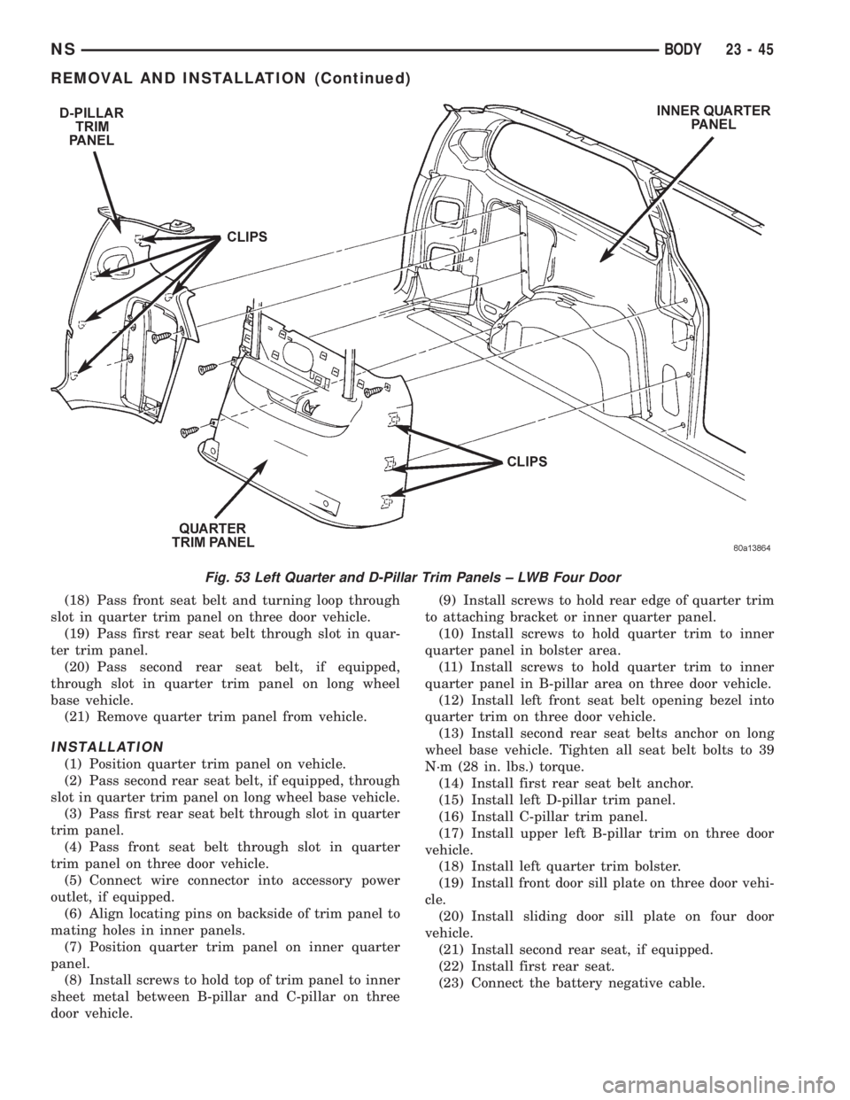
(18) Pass front seat belt and turning loop through
slot in quarter trim panel on three door vehicle.
(19) Pass first rear seat belt through slot in quar-
ter trim panel.
(20) Pass second rear seat belt, if equipped,
through slot in quarter trim panel on long wheel
base vehicle.
(21) Remove quarter trim panel from vehicle.
INSTALLATION
(1) Position quarter trim panel on vehicle.
(2) Pass second rear seat belt, if equipped, through
slot in quarter trim panel on long wheel base vehicle.
(3) Pass first rear seat belt through slot in quarter
trim panel.
(4) Pass front seat belt through slot in quarter
trim panel on three door vehicle.
(5) Connect wire connector into accessory power
outlet, if equipped.
(6) Align locating pins on backside of trim panel to
mating holes in inner panels.
(7) Position quarter trim panel on inner quarter
panel.
(8) Install screws to hold top of trim panel to inner
sheet metal between B-pillar and C-pillar on three
door vehicle.(9) Install screws to hold rear edge of quarter trim
to attaching bracket or inner quarter panel.
(10) Install screws to hold quarter trim to inner
quarter panel in bolster area.
(11) Install screws to hold quarter trim to inner
quarter panel in B-pillar area on three door vehicle.
(12) Install left front seat belt opening bezel into
quarter trim on three door vehicle.
(13) Install second rear seat belts anchor on long
wheel base vehicle. Tighten all seat belt bolts to 39
N´m (28 in. lbs.) torque.
(14) Install first rear seat belt anchor.
(15) Install left D-pillar trim panel.
(16) Install C-pillar trim panel.
(17) Install upper left B-pillar trim on three door
vehicle.
(18) Install left quarter trim bolster.
(19) Install front door sill plate on three door vehi-
cle.
(20) Install sliding door sill plate on four door
vehicle.
(21) Install second rear seat, if equipped.
(22) Install first rear seat.
(23) Connect the battery negative cable.
Fig. 53 Left Quarter and D-Pillar Trim Panels ± LWB Four Door
NSBODY 23 - 45
REMOVAL AND INSTALLATION (Continued)