1996 CHRYSLER VOYAGER battery
[x] Cancel search: batteryPage 1786 of 1938
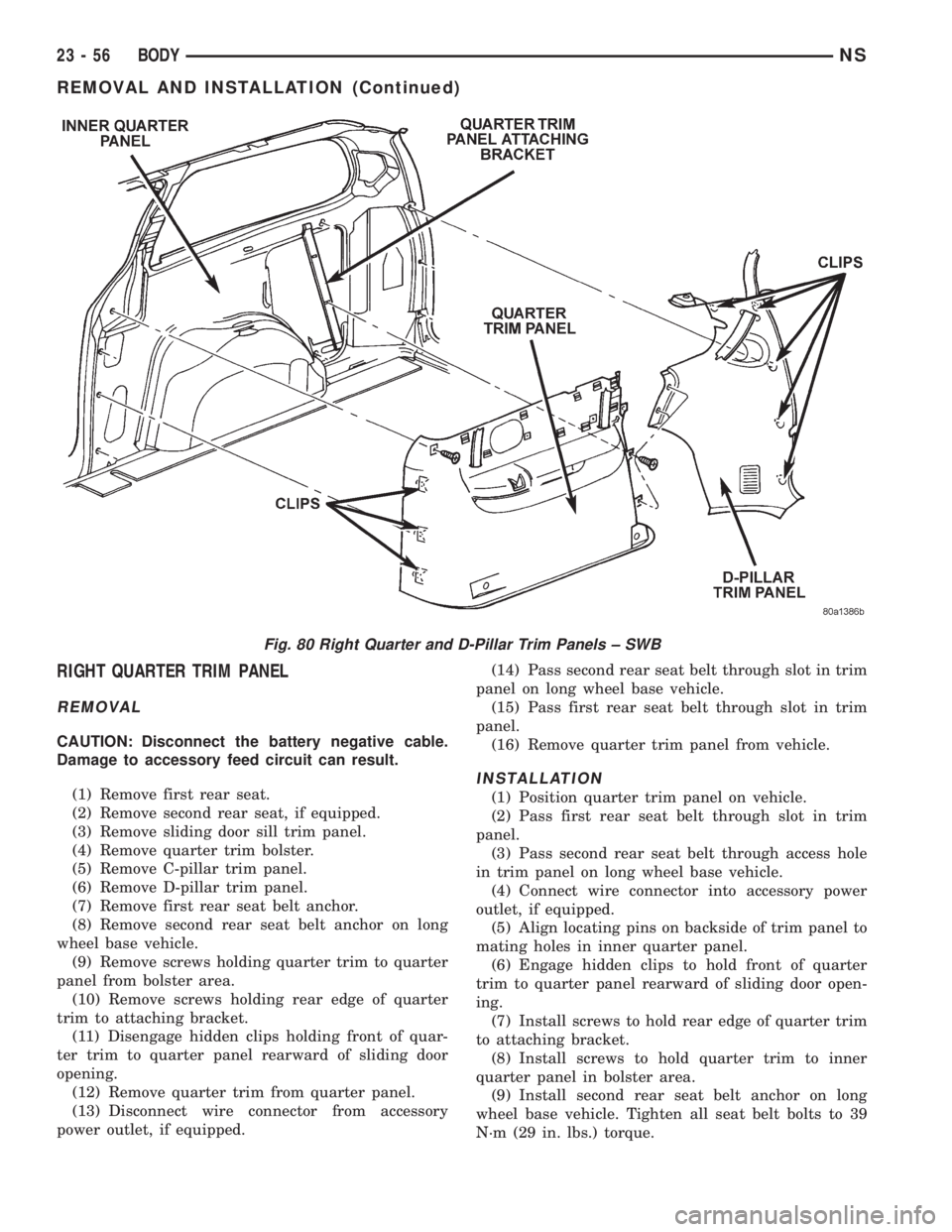
RIGHT QUARTER TRIM PANEL
REMOVAL
CAUTION: Disconnect the battery negative cable.
Damage to accessory feed circuit can result.
(1) Remove first rear seat.
(2) Remove second rear seat, if equipped.
(3) Remove sliding door sill trim panel.
(4) Remove quarter trim bolster.
(5) Remove C-pillar trim panel.
(6) Remove D-pillar trim panel.
(7) Remove first rear seat belt anchor.
(8) Remove second rear seat belt anchor on long
wheel base vehicle.
(9) Remove screws holding quarter trim to quarter
panel from bolster area.
(10) Remove screws holding rear edge of quarter
trim to attaching bracket.
(11) Disengage hidden clips holding front of quar-
ter trim to quarter panel rearward of sliding door
opening.
(12) Remove quarter trim from quarter panel.
(13) Disconnect wire connector from accessory
power outlet, if equipped.(14) Pass second rear seat belt through slot in trim
panel on long wheel base vehicle.
(15) Pass first rear seat belt through slot in trim
panel.
(16) Remove quarter trim panel from vehicle.
INSTALLATION
(1) Position quarter trim panel on vehicle.
(2) Pass first rear seat belt through slot in trim
panel.
(3) Pass second rear seat belt through access hole
in trim panel on long wheel base vehicle.
(4) Connect wire connector into accessory power
outlet, if equipped.
(5) Align locating pins on backside of trim panel to
mating holes in inner quarter panel.
(6) Engage hidden clips to hold front of quarter
trim to quarter panel rearward of sliding door open-
ing.
(7) Install screws to hold rear edge of quarter trim
to attaching bracket.
(8) Install screws to hold quarter trim to inner
quarter panel in bolster area.
(9) Install second rear seat belt anchor on long
wheel base vehicle. Tighten all seat belt bolts to 39
N´m (29 in. lbs.) torque.
Fig. 80 Right Quarter and D-Pillar Trim Panels ± SWB
23 - 56 BODYNS
REMOVAL AND INSTALLATION (Continued)
Page 1787 of 1938
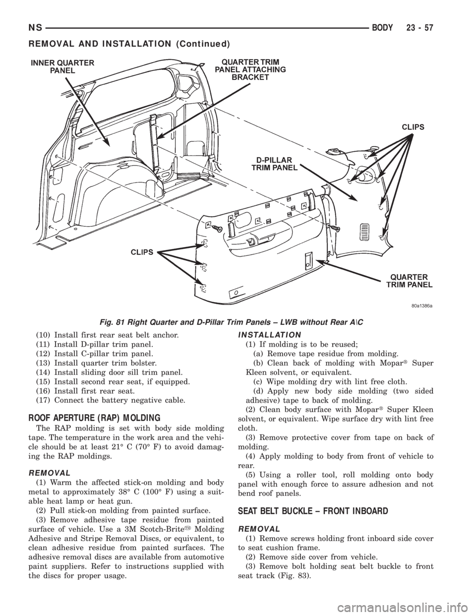
(10) Install first rear seat belt anchor.
(11) Install D-pillar trim panel.
(12) Install C-pillar trim panel.
(13) Install quarter trim bolster.
(14) Install sliding door sill trim panel.
(15) Install second rear seat, if equipped.
(16) Install first rear seat.
(17) Connect the battery negative cable.
ROOF APERTURE (RAP) MOLDING
The RAP molding is set with body side molding
tape. The temperature in the work area and the vehi-
cle should be at least 21É C (70É F) to avoid damag-
ing the RAP moldings.
REMOVAL
(1) Warm the affected stick-on molding and body
metal to approximately 38É C (100É F) using a suit-
able heat lamp or heat gun.
(2) Pull stick-on molding from painted surface.
(3) Remove adhesive tape residue from painted
surface of vehicle. Use a 3M Scotch-BriteyMolding
Adhesive and Stripe Removal Discs, or equivalent, to
clean adhesive residue from painted surfaces. The
adhesive removal discs are available from automotive
paint suppliers. Refer to instructions supplied with
the discs for proper usage.
INSTALLATION
(1) If molding is to be reused;
(a) Remove tape residue from molding.
(b) Clean back of molding with MopartSuper
Kleen solvent, or equivalent.
(c) Wipe molding dry with lint free cloth.
(d) Apply new body side molding (two sided
adhesive) tape to back of molding.
(2) Clean body surface with MopartSuper Kleen
solvent, or equivalent. Wipe surface dry with lint free
cloth.
(3) Remove protective cover from tape on back of
molding.
(4) Apply molding to body from front of vehicle to
rear.
(5) Using a roller tool, roll molding onto body
panel with enough force to assure adhesion and not
bend roof panels.
SEAT BELT BUCKLE ± FRONT INBOARD
REMOVAL
(1) Remove screws holding front inboard side cover
to seat cushion frame.
(2) Remove side cover from vehicle.
(3) Remove bolt holding seat belt buckle to front
seat track (Fig. 83).
Fig. 81 Right Quarter and D-Pillar Trim Panels ± LWB without Rear A\C
NSBODY 23 - 57
REMOVAL AND INSTALLATION (Continued)
Page 1826 of 1938
After calibration, Rear Wiper LED flashing
once, Intermittent LED flashing once. The
mode actuator did not reach defrost position.
(1) Using a voltmeter, check the mode door actua-
tor wiring connector. Check Pin 1 for battery voltage.
Move the HVAC control from the defrost to panel
position, and check Pin 6 voltage it should change
from 0.5 - 1 volts to 3.5 - 4.5 volts. If voltage is OK,
go to Step 2. If not OK, check for loose or corroded
connector, open or shorted circuit and repair as nec-
essary.
(2) Remove actuator, and check if the gear pins are
in the correct track on cam or if they are binding. If
OK, go to Step 3. If not OK, repair as necessary.
(3) Check for binding door, if door is binding repair
as necessary. If gears and door are OK, replace
actuator.
(4) Once repairs are completed repeat the Calibra-
tion Diagnostic and Cooldown test. Repeating the
test is necessary to clear the fault codes.
After calibration, Rear Wiper LED flashing
once, Intermittent LED flashing twice. The
mode actuator did not reach panel position.
(1) Using a voltmeter, check the mode door actua-
tor wiring connector. Check Pin 1 for battery voltage.
Move the HVAC control from panel to defrost posi-
tion, and check Pin 6 voltage it should change from
3.5 - 4.5 volts to 0.5 - 1 volts. If voltage is OK, go to
Step 2. If not OK, check for loose or corroded connec-
tor, open or shorted circuit and repair as necessary.
(2) Remove actuator, and check if the gear pins are
in the correct cam track or binding. If OK, go to Step
3. If not OK, repair as necessary.
(3) Check for binding door, if door is binding repair
as necessary. If gears and door are OK, replace
actuator.
(4) Once repairs are completed repeat the Calibra-
tion Diagnostic and Cooldown test. Repeating the
test is necessary to clear the fault codes.
After calibration, Rear Wiper LED flashing
once, Intermittent LED flashing three times.
The main temperature actuator/passenger
temperature actuator on a zone system did
not reach cold stop.
(1) Check if the correct HVAC control module was
used.
(2) Using a voltmeter, check the temperature door
actuator wiring connector. Check Pin 1 for battery
voltage. Move the HVAC control from the cold to hot
position, and check Pin 5 voltage it should change
from 0.5 - 4 volts to 3.5 - 4.5 volts. If voltage is OK,
go to Step 3. If not OK, check for loose or corroded
connector, open or shorted circuit and repair as nec-
essary.(3) Remove actuator, and check if gear pins are in
the correct cam track or binding. If OK, go to Step 4.
If not OK, repair as necessary.
(4) Check for binding door, if door is binding repair
as necessary. If gears and door are OK, replace
actuator.
(5) Once repairs are completed repeat the Calibra-
tion Diagnostic and Cooldown test. Repeating the
test is necessary to clear the fault codes.
After calibration, Rear Wiper LED flashing
once, Intermittent LED flashing four times.
The main temperature actuator/passenger
temperature actuator on a zone system did
not reach hot stop.
(1) Check if the correct HVAC control module was
used.
(2) Using a voltmeter, check the temperature door
actuator wiring connector. Check Pin 1 for battery
voltage. Move the HVAC control from hot to cold
position and check Pin 5 voltage it should change
from 3.5 -4.5 volts 0.5 - 1.5 volts. If voltage is OK, go
to Step 3. If not OK, check for loose or corroded con-
nector, open or shorted circuit and repair as neces-
sary.
(3) Remove actuator, and check if the gear pins are
in the correct track on cam or if they are binding. If
OK, go to Step 4. If not OK, repair as necessary.
(4) Check for binding door, if door is binding repair
as necessary. If gears and door are OK, replace
actuator.
(5) Once repairs are completed repeat the Calibra-
tion Diagnostic and Cooldown test. Repeating the
test is necessary to clear the fault codes.
After calibration, Rear Wiper LED flashing
once, Intermittent LED flashing five times.
The evaporator probe is open.
(1) Using a voltmeter, check Pin 1 of the evapora-
tor probe wiring connector for 0.1 - 4.75 volts. If OK,
go to Step 2. If not OK, if greater than 4.75 volts
check for loose or corroded connector, open circuit
and repair as necessary.
(2) Using a ohmmeter, check Pin 2 for a good
ground, If OK, go to Step 3. If not OK, check for loose
or corroded connector, open or shorted circuit and
repair as necessary.
(3) If ground and power circuit are OK, replace
Evaporator Probe.
(4) Once repairs are completed, press the intermit-
tent button about 5 seconds until all LED's light to
remove fault code from memory. Then repeat the Cal-
ibration Diagnostic and Cooldown test. Repeating the
test is necessary to clear the fault codes.
24 - 10 HEATING AND AIR CONDITIONINGNS
DIAGNOSIS AND TESTING (Continued)
Page 1829 of 1938
BLOWER MOTOR AND WHEEL ASSEMBLY
VIBRATION AND/OR NOISE DIAGNOSIS
The blower speed switch, in conjunction with the
resistor block, supplies the blower motor with varied
voltage.
CAUTION: Stay clear of the blower motor and resis-
tor block (Hot). Do not operate the blower motor
with the resistor block removed from the heater A/C
housing.
Refer to the Blower Motor Vibration/Noise chart in
this section for diagnosis.
COMPRESSOR NOISE DIAGNOSIS
Excessive noise while the A/C is being used, can be
caused by loose mounts, loose clutch, or high operat-
ing pressure. Verify compressor drive belt condition,
proper refrigerant charge and head pressure before
compressor repair is performed.
If the A/C drive belt slips at initial start-up, it does
not necessarily mean the compressor has failed.
With the close tolerances of a compressor it is pos-
sible to experience a temporary lockup. The longer
the A/C system is inactive, the more likely the condi-
tion to occur.
This condition is the result of normal refrigerant
movement within the A/C system caused by temper-
ature changes. The refrigerant movement may wash
the oil out of the compressor.
COMPRESSOR CLUTCH/COIL
The air conditioning compressor clutch electrical
circuit is controlled by the Powertrain Control Mod-
ule. It is located in the engine compartment outboard
of the battery.If the compressor clutch does not engage verify
refrigerant charge.
If the compressor clutch still does not engage check
for battery voltage at the pressure transducer located
on the liquid line. If voltage is not detected, refer to:
²Group 8W, Wiring diagrams.
²Powertrain Diagnostic Procedures manual for
diagnostic information.
If voltage is detected at the pressure transducer,
connect pressure transducer and check for battery
voltage between the compressor clutch connector ter-
minals.
If voltage is detected, perform A/C Clutch Coil
Tests.
TESTS
(1) Verify battery state of charge. (Test indicator in
battery should be green).
(2) Connect an ampmeter (0-10 ampere scale) in
series with the clutch coil terminal. Use a voltmeter
(0-20 volt scale) with clip leads measuring voltage
across the battery and A/C clutch.
(3) With A/C control in A/C mode and blower at
low speed, start the engine and run at normal idle.
(4) The A/C clutch should engage immediately and
the clutch voltage should be within two volts of the
battery voltage. If the A/C clutch does not engage,
test the fuse.
(5) The A/C clutch coil is acceptable if the current
draw is 2.0 to 3.7 amperes at 11.5-12.5 volts at clutch
coil. This is with the work area temperature at 21ÉC
(70ÉF). If voltage is more than 12.5 volts, add electri-
cal loads by turning on electrical accessories until
voltage reads below 12.5 volts.
(6) If coil current reads zero, the coil is open and
should be replaced. If the ammeter reading is 4
amperes or more, the coil is shorted and should be
replaced. If the coil voltage is not within two volts of
the battery voltage, test clutch coil feed circuit for
excessive voltage drop.
EXPANSION VALVE
NOTE: Special effort must be used to keep all
R-134a system components moisture-free. Moisture
in the oil is very difficult to remove and will cause a
reliability problem with the compressor.
TESTS
NOTE: Expansion valve tests should be performed
after compressor tests.
Review Safety Precautions and Warnings in this
group. The work area and vehicle temperature must
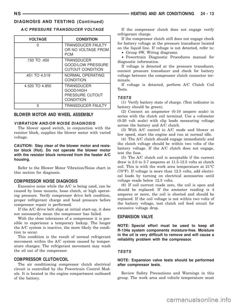
A/C PRESSURE TRANSDUCER VOLTAGE
VOLTAGE CONDITION
0 TRANSDUCER FAULTY
OR NO VOLTAGE FROM
PCM
.150 TO .450 TRANSDUCER
GOOD/LOW PRESSURE
CUTOUT CONDITION
.451 TO 4.519 NORMAL OPERATING
CONDITION
4.520 TO 4.850 TRANSDUCER
GOOD/HIGH
PRESSURE CUTOUT
CONDITION
5 TRANSDUCER FAULTY
NSHEATING AND AIR CONDITIONING 24 - 13
DIAGNOSIS AND TESTING (Continued)
Page 1836 of 1938
²Transaxle in Park
²Engine Idling at 700 rpm
²A/C Controls Set in 100 percent outside air
²Full Panel Mode
²Blower motor ON HIGH
²A/C in the ON position
²Front Windows Open.
²Rear Air Off (If Equipped)
CAUTION: A leak detector designed for R-12 refrig-
erant will not detect leaks in a R-134a refrigerant
system.
(4) Shut off the vehicle and wait 2 to 7 minutes.
Then use an Electronic Leak Detector that is
designed to detect R-134a type refrigerant and search
for leaks. Fittings, lines, or components that appear
to be oily usually indicates a refrigerant leak. To
inspect the evaporator core for leaks, insert the leak
detector probe into the recirculating air door opening
or a heat duct.
If a thorough leak check has been completed with-
out indication of a leak, proceed to System Charge
Level-Check or Fill.
REMOVAL AND INSTALLATION
A/C PRESSURE TRANSDUCER
REMOVAL
(1) Disconnect the wire connector at the pressure
transducer.
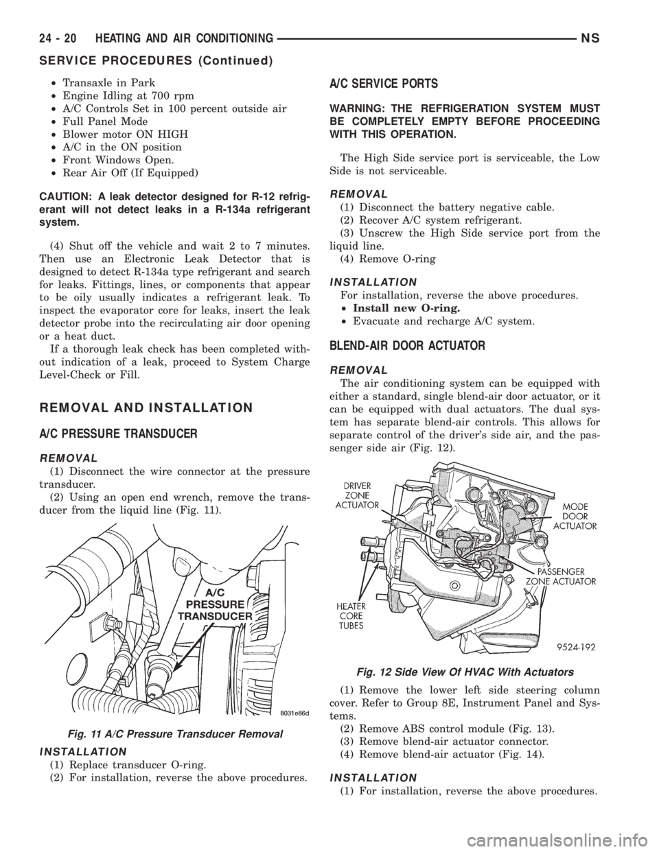
(2) Using an open end wrench, remove the trans-
ducer from the liquid line (Fig. 11).
INSTALLATION
(1) Replace transducer O-ring.
(2) For installation, reverse the above procedures.
A/C SERVICE PORTS
WARNING: THE REFRIGERATION SYSTEM MUST
BE COMPLETELY EMPTY BEFORE PROCEEDING
WITH THIS OPERATION.
The High Side service port is serviceable, the Low
Side is not serviceable.
REMOVAL
(1) Disconnect the battery negative cable.
(2) Recover A/C system refrigerant.
(3) Unscrew the High Side service port from the
liquid line.
(4) Remove O-ring
INSTALLATION
For installation, reverse the above procedures.
²Install new O-ring.
²Evacuate and recharge A/C system.
BLEND-AIR DOOR ACTUATOR
REMOVAL
The air conditioning system can be equipped with
either a standard, single blend-air door actuator, or it
can be equipped with dual actuators. The dual sys-
tem has separate blend-air controls. This allows for
separate control of the driver's side air, and the pas-
senger side air (Fig. 12).
(1) Remove the lower left side steering column
cover. Refer to Group 8E, Instrument Panel and Sys-
tems.
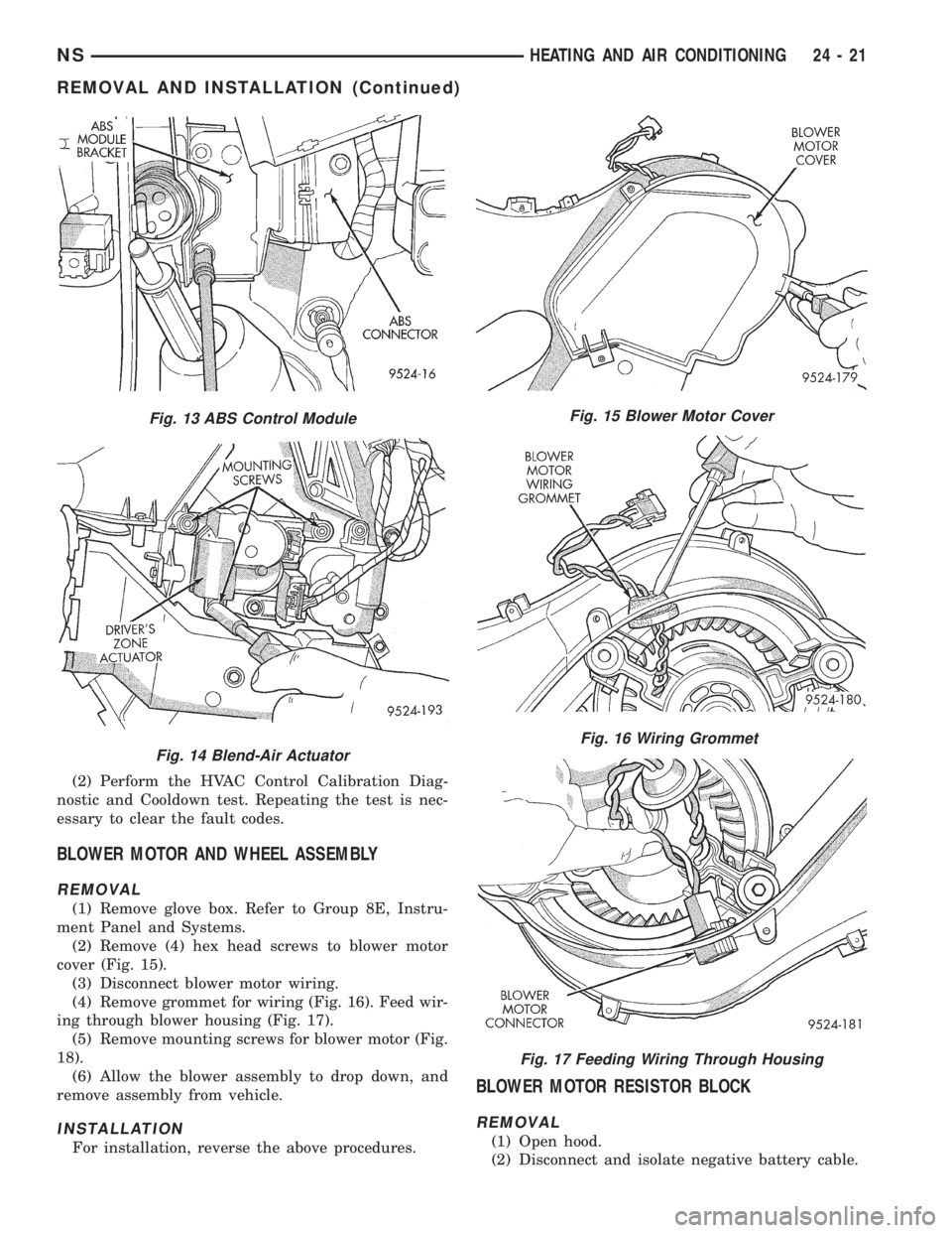
(2) Remove ABS control module (Fig. 13).
(3) Remove blend-air actuator connector.
(4) Remove blend-air actuator (Fig. 14).
INSTALLATION
(1) For installation, reverse the above procedures.
Fig. 11 A/C Pressure Transducer Removal
Fig. 12 Side View Of HVAC With Actuators
24 - 20 HEATING AND AIR CONDITIONINGNS
SERVICE PROCEDURES (Continued)
Page 1837 of 1938
(2) Perform the HVAC Control Calibration Diag-
nostic and Cooldown test. Repeating the test is nec-
essary to clear the fault codes.
BLOWER MOTOR AND WHEEL ASSEMBLY
REMOVAL
(1) Remove glove box. Refer to Group 8E, Instru-
ment Panel and Systems.
(2) Remove (4) hex head screws to blower motor
cover (Fig. 15).
(3) Disconnect blower motor wiring.
(4) Remove grommet for wiring (Fig. 16). Feed wir-
ing through blower housing (Fig. 17).
(5) Remove mounting screws for blower motor (Fig.
18).
(6) Allow the blower assembly to drop down, and
remove assembly from vehicle.
INSTALLATION
For installation, reverse the above procedures.
BLOWER MOTOR RESISTOR BLOCK
REMOVAL
(1) Open hood.
(2) Disconnect and isolate negative battery cable.
Fig. 13 ABS Control Module
Fig. 14 Blend-Air Actuator
Fig. 15 Blower Motor Cover
Fig. 16 Wiring Grommet
Fig. 17 Feeding Wiring Through Housing
NSHEATING AND AIR CONDITIONING 24 - 21
REMOVAL AND INSTALLATION (Continued)
Page 1839 of 1938
COMPRESSOR
REMOVAL
WARNING: REFER TO REFRIGERANT SERVICE
PROCEDURES FOR INFORMATION REGARDING
PROPER RECOVERY OF THE REFRIGERANT
BEFORE ATTEMPTING TO REMOVE THE COM-
PRESSOR.
(1) Disconnect negative battery cable.
(2) Pinch off coolant lines to rear Heat unit (if
equipped). Drain engine coolant.
(3) Remove upper radiator hose.
(4) Remove drive belt (refer to Group 7, Cooling
System). Disconnect compressor clutch wire lead.
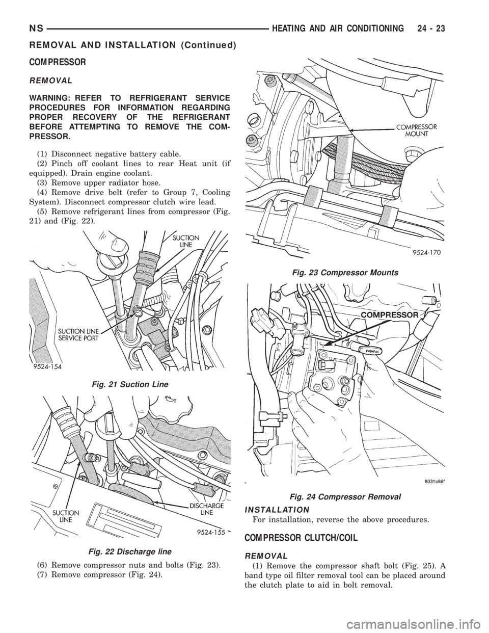
(5) Remove refrigerant lines from compressor (Fig.
21) and (Fig. 22).
(6) Remove compressor nuts and bolts (Fig. 23).
(7) Remove compressor (Fig. 24).
INSTALLATION
For installation, reverse the above procedures.
COMPRESSOR CLUTCH/COIL
REMOVAL
(1) Remove the compressor shaft bolt (Fig. 25). A
band type oil filter removal tool can be placed around
the clutch plate to aid in bolt removal.
Fig. 21 Suction Line
Fig. 22 Discharge line
Fig. 23 Compressor Mounts
Fig. 24 Compressor Removal
NSHEATING AND AIR CONDITIONING 24 - 23
REMOVAL AND INSTALLATION (Continued)
Page 1844 of 1938
EXPANSION VALVE
WARNING: THE REFRIGERATION SYSTEM MUST
BE COMPLETELY EMPTY BEFORE PROCEEDING
WITH THIS OPERATION.
REMOVAL
(1) Disconnect the battery negative cable.
(2) Recover A/C system refrigerant.
(3) Remove the accessory drive belt.
(4) Remove upper generator bracket.
(5) Disconnect generator field wire connector.
(6) Push generator forward.
(7) Remove ground wire at dash panel.
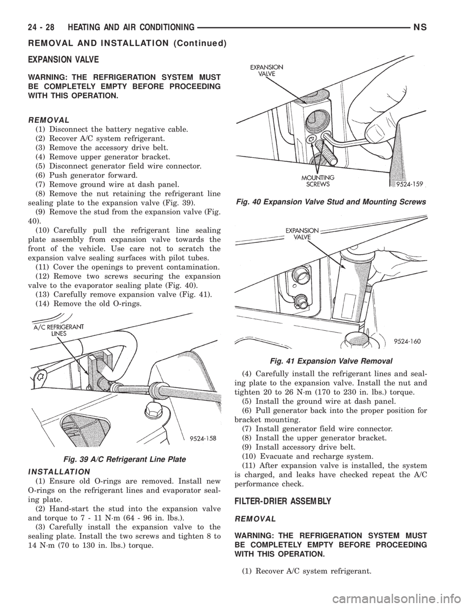
(8) Remove the nut retaining the refrigerant line
sealing plate to the expansion valve (Fig. 39).
(9) Remove the stud from the expansion valve (Fig.
40).
(10) Carefully pull the refrigerant line sealing
plate assembly from expansion valve towards the
front of the vehicle. Use care not to scratch the
expansion valve sealing surfaces with pilot tubes.
(11) Cover the openings to prevent contamination.
(12) Remove two screws securing the expansion
valve to the evaporator sealing plate (Fig. 40).
(13) Carefully remove expansion valve (Fig. 41).
(14) Remove the old O-rings.
INSTALLATION
(1) Ensure old O-rings are removed. Install new
O-rings on the refrigerant lines and evaporator seal-
ing plate.
(2) Hand-start the stud into the expansion valve
and torque to7-11N´m(64-96in.lbs.).
(3) Carefully install the expansion valve to the
sealing plate. Install the two screws and tighten 8 to
14 N´m (70 to 130 in. lbs.) torque.(4) Carefully install the refrigerant lines and seal-
ing plate to the expansion valve. Install the nut and
tighten 20 to 26 N´m (170 to 230 in. lbs.) torque.
(5) Install the ground wire at dash panel.
(6) Pull generator back into the proper position for
bracket mounting.
(7) Install generator field wire connector.
(8) Install the upper generator bracket.
(9) Install accessory drive belt.
(10) Evacuate and recharge system.
(11) After expansion valve is installed, the system
is charged, and leaks have checked repeat the A/C
performance check.
FILTER-DRIER ASSEMBLY
REMOVAL
WARNING: THE REFRIGERATION SYSTEM MUST
BE COMPLETELY EMPTY BEFORE PROCEEDING
WITH THIS OPERATION.
(1) Recover A/C system refrigerant.
Fig. 39 A/C Refrigerant Line Plate
Fig. 40 Expansion Valve Stud and Mounting Screws
Fig. 41 Expansion Valve Removal
24 - 28 HEATING AND AIR CONDITIONINGNS
REMOVAL AND INSTALLATION (Continued)