1996 CHRYSLER VOYAGER battery
[x] Cancel search: batteryPage 1377 of 1938
DIAGNOSIS AND TESTING
GENERAL INFORMATION
This section of the group will cover a general diag-
nosis of diesel engine fuel system components.
Diagnostic Trouble Codes:Refer to On-Board
Diagnostics in Group 25, Emission Control System
for a list of Diagnostic Trouble Codes (DTC's) for cer-
tain fuel system components.
The PCM must be tested with the DRBIII scan
tool. The DRBIII should be the first step in any diag-
nosis of engine performance complaints. Refer to the
1997 GS 2.5L Diesel Powertrain Diagnostic Proce-
dures manual for diagnosis and testing of the diesel
engine control system.
VISUAL INSPECTION
A visual inspection for loose, disconnected, or incor-
rectly routed wires and hoses should be made before
attempting to diagnose or service the diesel fuel
injection system. A visual check will help find these
conditions. It also saves unnecessary test and diag-
nostic time. A thorough visual inspection of the fuel
injection system includes the following checks:
(1) Be sure that the battery connections are tight
and not corroded.
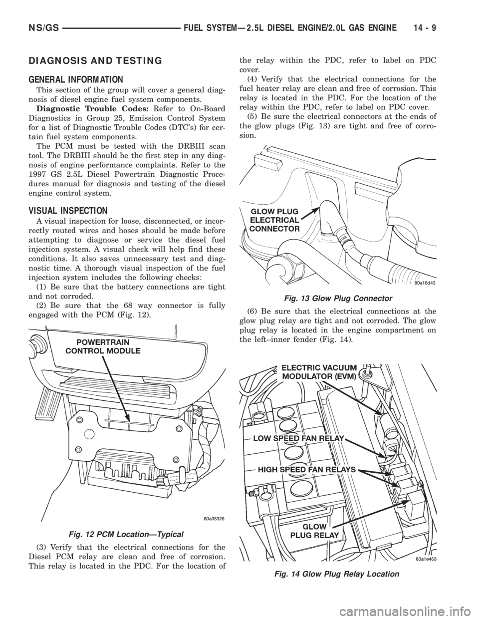
(2) Be sure that the 68 way connector is fully
engaged with the PCM (Fig. 12).
(3) Verify that the electrical connections for the
Diesel PCM relay are clean and free of corrosion.
This relay is located in the PDC. For the location ofthe relay within the PDC, refer to label on PDC
cover.
(4) Verify that the electrical connections for the
fuel heater relay are clean and free of corrosion. This
relay is located in the PDC. For the location of the
relay within the PDC, refer to label on PDC cover.
(5) Be sure the electrical connectors at the ends of
the glow plugs (Fig. 13) are tight and free of corro-
sion.
(6) Be sure that the electrical connections at the
glow plug relay are tight and not corroded. The glow
plug relay is located in the engine compartment on
the left±inner fender (Fig. 14).
Fig. 12 PCM LocationÐTypical
Fig. 13 Glow Plug Connector
Fig. 14 Glow Plug Relay Location
NS/GSFUEL SYSTEMÐ2.5L DIESEL ENGINE/2.0L GAS ENGINE 14 - 9
Page 1381 of 1938
A defective fuel injection pump, defective fuel tim-
ing solenoid or misadjusted mechanical pump timing
can cause starting problems or prevent the engine
from revving up. It can also cause:
²Engine surge at idle
²Rough idle (warm engine)
²Low power
²Excessive fuel consumption
²Poor performance
²Low power
²Black smoke from the exhaust
²Blue or white fog like exhaust
²Incorrect idle or maximum speed
The electronically controlled fuel pump has no
mechanical governor like older mechanically con-
trolled fuel pumps. Do not remove the top cover of
the fuel pump, or the screws fastening the wiring
pigtail to the side of the pump.The warranty of
the injection pump and the engine may be void
if those seals have been removed or tampered
with.
FUEL SUPPLY RESTRICTIONS
LOW±PRESSURE LINES
Restricted or Plugged supply lines or fuel filter can
cause a timing fault that will cause the PCM to oper-
ate the engine in a ªLimp Homeº mode. See the
introduction of the Fuel Injection System in this
group for more information on the Limp Home mode.
Fuel supply line restrictions can cause starting prob-
lems and prevent the engine from revving up. The
starting problems include; low power and blue or
white fog like exhaust. Test all fuel supply lines for
restrictions or blockage. Flush or replace as neces-
sary. Bleed the fuel system of air once a fuel supply
line has been replaced. Refer to the Air Bleed Proce-
dure section of this group for procedures.
HIGH±PRESSURE LINES
Restricted (kinked or bent) high±pressure lines can
cause starting problems, poor engine performance
and black smoke from exhaust.
Examine all high±pressure lines for any damage.
Each radius on each high±pressure line must be
smooth and free of any bends or kinks.
Replace damaged, restricted or leaking high±pres-
sure fuel lines with the correct replacement line.
CAUTION: The high±pressure fuel lines must be
clamped securely in place in the holders. The lines
cannot contact each other or other components. Do
not attempt to weld high±pressure fuel lines or to
repair lines that are damaged. Only use the recom-
mended lines when replacement of high±pressure
fuel line is necessary.
FUEL SHUTDOWN SOLENOID TEST
Since diesel fuel injection does not use spark plugs
to start combustion, the only way to stop the engine
is to cut off the fuel supply. This is done with the
Fuel Shutdown Solenoid. If the engine cranks, but
refuses to start, it may be caused by a defective fuel
shutdown solenoid.
The fuel shutdown solenoid is not controlled
or operated by the PCM.Voltage to operate the
solenoid is supplied from the ignition (key) switch.
NOTE: Although the fuel shutdown solenoid is not
operated by the PCM, if the Fuel Shutdown Solenoid
has been disconnected, and the key turned on, the
PCM will sense that the solenoid is not in the circuit,
and will switch to a ªLimp Homeº mode. After recon-
necting the solenoid, the PCM will have to be reset
by clearing the codes with the DRBIII scan tool, or
disconnecting the vehicle's battery for several min-
utes. The DRBIII scan tool is the preferred method
for resetting the PCM. Refer to the 1998 GS 2.5L Die-
sel Powertrain Diagnostic Manual for procedure.
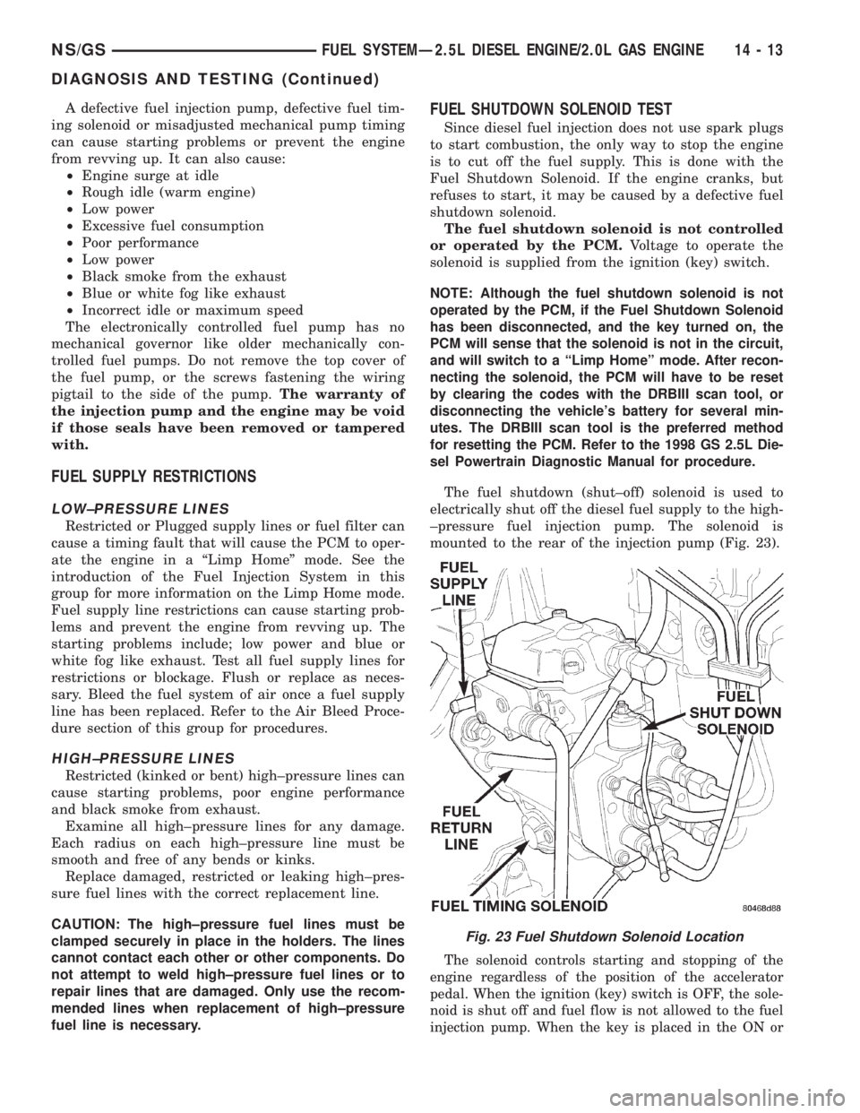
The fuel shutdown (shut±off) solenoid is used to
electrically shut off the diesel fuel supply to the high-
±pressure fuel injection pump. The solenoid is
mounted to the rear of the injection pump (Fig. 23).
The solenoid controls starting and stopping of the
engine regardless of the position of the accelerator
pedal. When the ignition (key) switch is OFF, the sole-
noid is shut off and fuel flow is not allowed to the fuel
injection pump. When the key is placed in the ON or
Fig. 23 Fuel Shutdown Solenoid Location
NS/GSFUEL SYSTEMÐ2.5L DIESEL ENGINE/2.0L GAS ENGINE 14 - 13
DIAGNOSIS AND TESTING (Continued)
Page 1387 of 1938
INSTALLATION
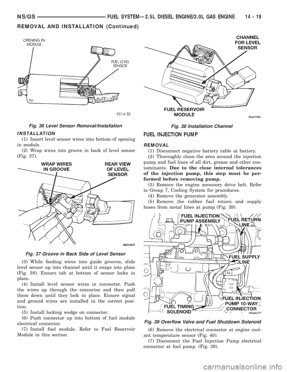
(1) Insert level sensor wires into bottom of opening
in module.
(2) Wrap wires into groove in back of level sensor
(Fig. 37).
(3) While feeding wires into guide grooves, slide
level sensor up into channel until it snaps into place
(Fig. 38). Ensure tab at bottom of sensor locks in
place.
(4) Install level sensor wires in connector. Push
the wires up through the connector and then pull
them down until they lock in place. Ensure signal
and ground wires are installed in the correct posi-
tion.
(5) Install locking wedge on connector.
(6) Push connector up into bottom of fuel module
electrical connector.
(7) Install fuel module. Refer to Fuel Reservoir
Module in this section.FUEL INJECTION PUMP
REMOVAL
(1) Disconnect negative battery cable at battery.
(2) Thoroughly clean the area around the injection
pump and fuel lines of all dirt, grease and other con-
taminants.Due to the close internal tolerances
of the injection pump, this step must be per-
formed before removing pump.
(3) Remove the engine accessory drive belt. Refer
to Group 7, Cooling System for procedures.
(4) Remove the generator assembly.
(5) Remove the rubber fuel return and supply
hoses from metal lines at pump (Fig. 39).
(6) Remove the electrical connector at engine cool-
ant temperature sensor (Fig. 40).
(7) Disconnect the Fuel Injection Pump electrical
connector at fuel pump. (Fig. 39).
Fig. 36 Level Sensor Removal/Installation
Fig. 37 Groove in Back Side of Level Sensor
Fig. 38 Installation Channel
Fig. 39 Overflow Valve and Fuel Shutdown Solenoid
NS/GSFUEL SYSTEMÐ2.5L DIESEL ENGINE/2.0L GAS ENGINE 14 - 19
REMOVAL AND INSTALLATION (Continued)
Page 1390 of 1938
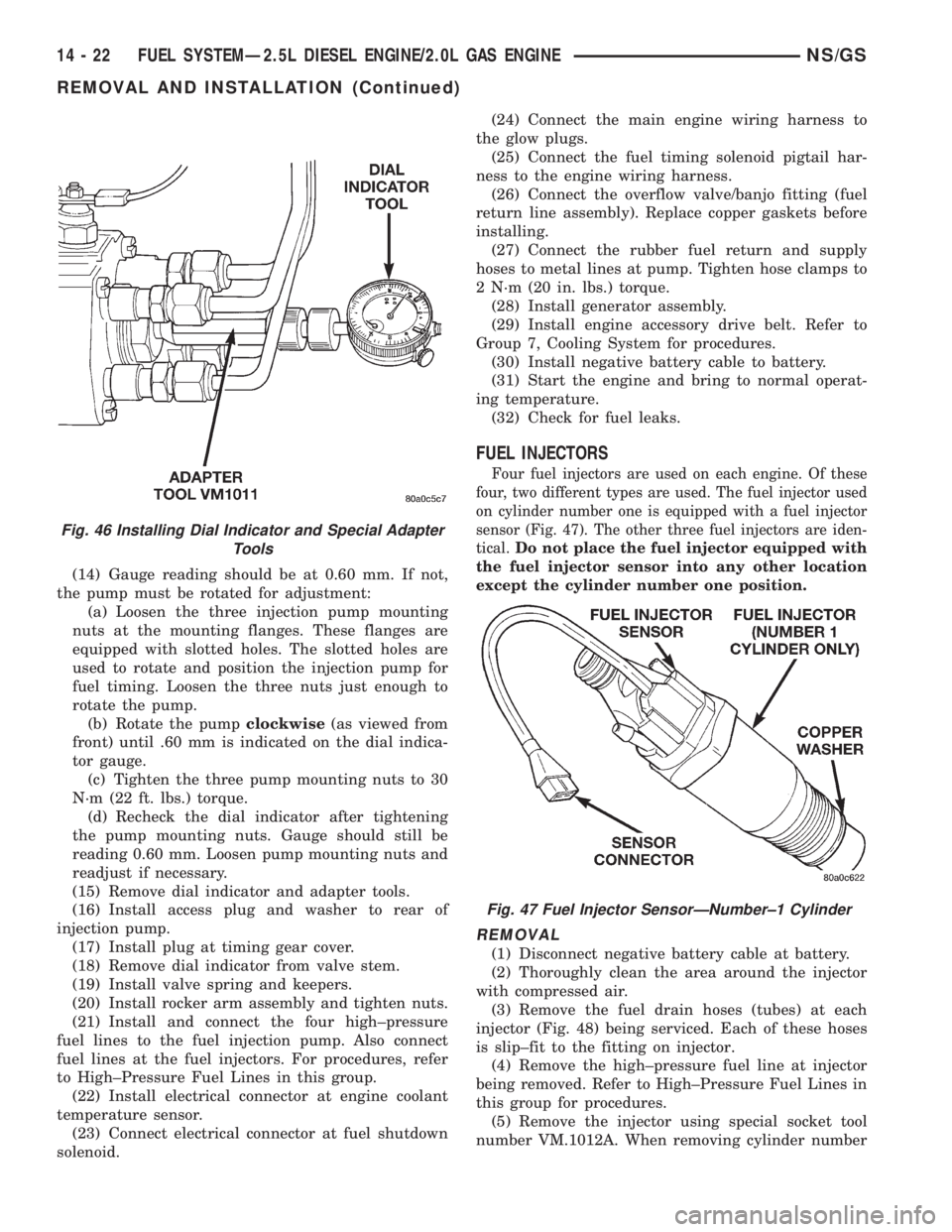
(14) Gauge reading should be at 0.60 mm. If not,
the pump must be rotated for adjustment:
(a) Loosen the three injection pump mounting
nuts at the mounting flanges. These flanges are
equipped with slotted holes. The slotted holes are
used to rotate and position the injection pump for
fuel timing. Loosen the three nuts just enough to
rotate the pump.
(b) Rotate the pumpclockwise(as viewed from
front) until .60 mm is indicated on the dial indica-
tor gauge.
(c) Tighten the three pump mounting nuts to 30
N´m (22 ft. lbs.) torque.
(d) Recheck the dial indicator after tightening
the pump mounting nuts. Gauge should still be
reading 0.60 mm. Loosen pump mounting nuts and
readjust if necessary.
(15) Remove dial indicator and adapter tools.
(16) Install access plug and washer to rear of
injection pump.
(17) Install plug at timing gear cover.
(18) Remove dial indicator from valve stem.
(19) Install valve spring and keepers.
(20) Install rocker arm assembly and tighten nuts.
(21) Install and connect the four high±pressure
fuel lines to the fuel injection pump. Also connect
fuel lines at the fuel injectors. For procedures, refer
to High±Pressure Fuel Lines in this group.
(22) Install electrical connector at engine coolant
temperature sensor.
(23) Connect electrical connector at fuel shutdown
solenoid.(24) Connect the main engine wiring harness to
the glow plugs.
(25) Connect the fuel timing solenoid pigtail har-
ness to the engine wiring harness.
(26) Connect the overflow valve/banjo fitting (fuel
return line assembly). Replace copper gaskets before
installing.
(27) Connect the rubber fuel return and supply
hoses to metal lines at pump. Tighten hose clamps to
2 N´m (20 in. lbs.) torque.
(28) Install generator assembly.
(29) Install engine accessory drive belt. Refer to
Group 7, Cooling System for procedures.
(30) Install negative battery cable to battery.
(31) Start the engine and bring to normal operat-
ing temperature.
(32) Check for fuel leaks.
FUEL INJECTORS
Four fuel injectors are used on each engine. Of these
four, two different types are used. The fuel injector used
on cylinder number one is equipped with a fuel injector
sensor (Fig. 47). The other three fuel injectors are iden-
tical.
Do not place the fuel injector equipped with
the fuel injector sensor into any other location
except the cylinder number one position.
REMOVAL
(1) Disconnect negative battery cable at battery.
(2) Thoroughly clean the area around the injector
with compressed air.
(3) Remove the fuel drain hoses (tubes) at each
injector (Fig. 48) being serviced. Each of these hoses
is slip±fit to the fitting on injector.
(4) Remove the high±pressure fuel line at injector
being removed. Refer to High±Pressure Fuel Lines in
this group for procedures.
(5) Remove the injector using special socket tool
number VM.1012A. When removing cylinder number
Fig. 46 Installing Dial Indicator and Special Adapter
Tools
Fig. 47 Fuel Injector SensorÐNumber±1 Cylinder
14 - 22 FUEL SYSTEMÐ2.5L DIESEL ENGINE/2.0L GAS ENGINENS/GS
REMOVAL AND INSTALLATION (Continued)
Page 1391 of 1938
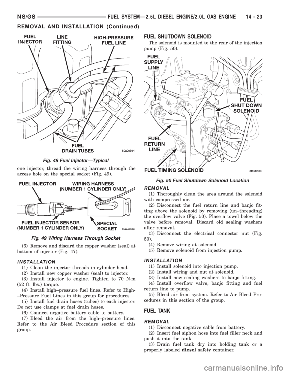
one injector, thread the wiring harness through the
access hole on the special socket (Fig. 49).
(6) Remove and discard the copper washer (seal) at
bottom of injector (Fig. 47).
INSTALLATION
(1) Clean the injector threads in cylinder head.
(2) Install new copper washer (seal) to injector.
(3) Install injector to engine. Tighten to 70 N´m
(52 ft. lbs.) torque.
(4) Install high±pressure fuel lines. Refer to High-
±Pressure Fuel Lines in this group for procedures.
(5) Install fuel drain hoses (tubes) to each injector.
Do not use clamps at fuel drain hoses.
(6) Connect negative battery cable to battery.
(7) Bleed the air from the high±pressure lines.
Refer to the Air Bleed Procedure section of this
group.
FUEL SHUTDOWN SOLENOID
The solenoid is mounted to the rear of the injection
pump (Fig. 50).
REMOVAL
(1) Thoroughly clean the area around the solenoid
with compressed air.
(2) Disconnect the fuel return line and banjo fit-
ting above the solenoid by removing (un±threading)
the overflow valve (Fig. 50). Place a towel below the
valve before removal. Discard old sealing washers
after removal.
(3) Disconnect the electrical connector nut (Fig.
50).
(4) Remove wiring at solenoid.
(5) Remove solenoid from injection pump.
INSTALLATION
(1) Install solenoid into injection pump.
(2) Install wiring and nut at solenoid.
(3) Install new sealing washers to banjo fitting.
(4) Install overflow valve, banjo fitting and fuel
return line to pump.
(5) Bleed air from system. Refer to Air Bleed Pro-
cedures in this section of the group.
FUEL TANK
REMOVAL
(1) Disconnect negative cable from battery.
(2) Insert fuel siphon hose into fuel filler neck and
push it into the tank.
(3) Drain fuel tank dry into holding tank or a
properly labeleddieselsafety container.
Fig. 48 Fuel InjectorÐTypical
Fig. 49 Wiring Harness Through Socket
Fig. 50 Fuel Shutdown Solenoid Location
NS/GSFUEL SYSTEMÐ2.5L DIESEL ENGINE/2.0L GAS ENGINE 14 - 23
REMOVAL AND INSTALLATION (Continued)
Page 1393 of 1938
fuel fitting. Refer to Tube/Fitting Assembly in the
Fuel Delivery section of this Group.
(7) Attach filler line to filler tube. Pull on connec-
tor to make sure of connection.
(8) Fill fuel tank, replace cap, and connect battery
negative cable.
FUEL RESERVOIR MODULE
REMOVAL
WARNING: THE FUEL RESERVOIR OF THE FUEL
MODULE DOES NOT EMPTY OUT WHEN THE TANK
IS DRAINED. THE FUEL IN THE RESERVOIR WILL
SPILL OUT WHEN THE MODULE IS REMOVED.
(1) Disconnect negative cable from battery.
(2) Insert fuel siphon hose into fuel filler neck and
push it into the tank.
(3) Drain fuel tank dry into holding tank or a
properly labeleddieselsafety container.
(4) Raise vehicle on hoist.
(5) Use a transmission jack to support the fuel
tank. Remove bolts from fuel tank straps. Lower
tank slightly.
(6) Clean area around fuel reservoir module and
tank to keep dirt and foreign material out of tank.
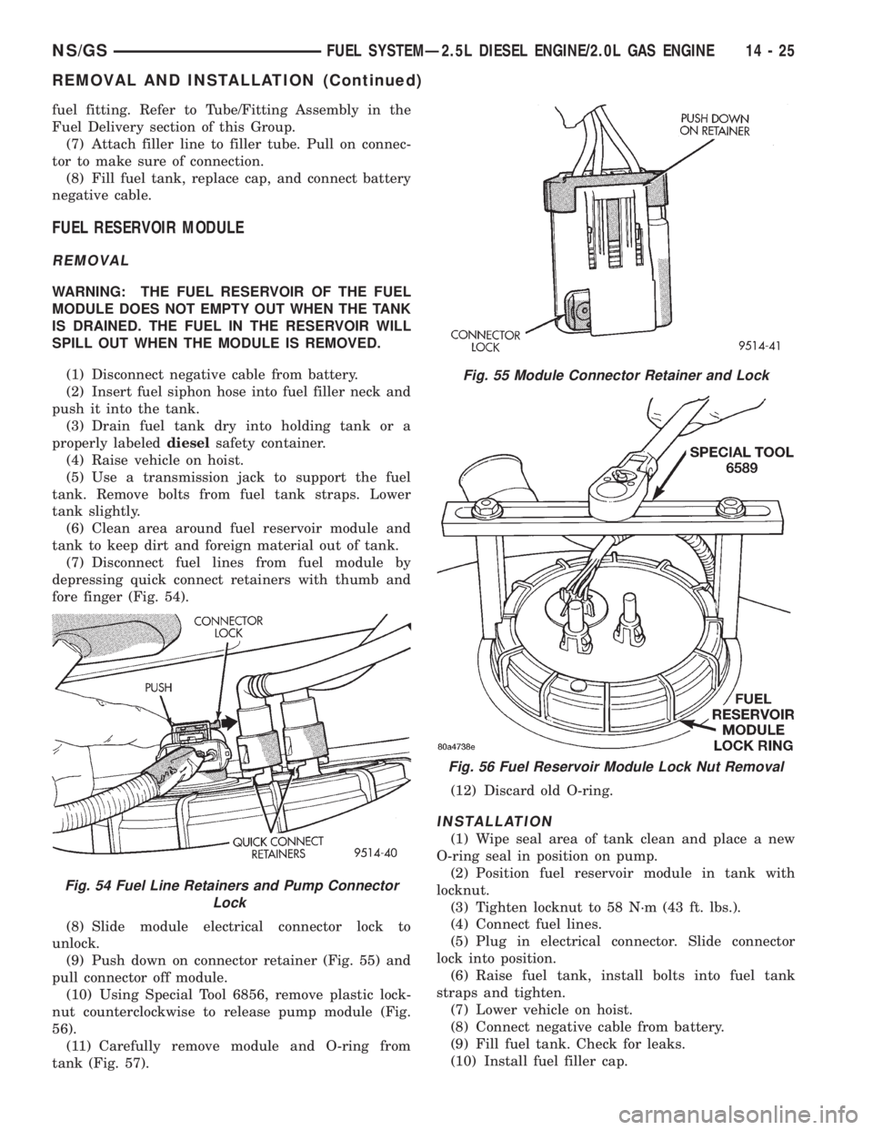
(7) Disconnect fuel lines from fuel module by
depressing quick connect retainers with thumb and
fore finger (Fig. 54).
(8) Slide module electrical connector lock to
unlock.
(9) Push down on connector retainer (Fig. 55) and
pull connector off module.
(10) Using Special Tool 6856, remove plastic lock-
nut counterclockwise to release pump module (Fig.
56).
(11) Carefully remove module and O-ring from
tank (Fig. 57).(12) Discard old O-ring.
INSTALLATION
(1) Wipe seal area of tank clean and place a new
O-ring seal in position on pump.
(2) Position fuel reservoir module in tank with
locknut.
(3) Tighten locknut to 58 N´m (43 ft. lbs.).
(4) Connect fuel lines.
(5) Plug in electrical connector. Slide connector
lock into position.
(6) Raise fuel tank, install bolts into fuel tank
straps and tighten.
(7) Lower vehicle on hoist.
(8) Connect negative cable from battery.
(9) Fill fuel tank. Check for leaks.
(10) Install fuel filler cap.
Fig. 54 Fuel Line Retainers and Pump Connector
Lock
Fig. 55 Module Connector Retainer and Lock
Fig. 56 Fuel Reservoir Module Lock Nut Removal
NS/GSFUEL SYSTEMÐ2.5L DIESEL ENGINE/2.0L GAS ENGINE 14 - 25
REMOVAL AND INSTALLATION (Continued)
Page 1394 of 1938
HIGH-PRESSURE LINES
All high±pressure fuel lines are of the same length
and inside diameter. Correct high±pressure fuel line
usage and installation is critical to smooth engine
operation.
CAUTION: The high±pressure fuel lines must be
clamped securely in place in the holders. The lines
cannot contact each other or other components. Do
not attempt to weld high±pressure fuel lines or to
repair lines that are damaged. Only use the recom-
mended lines when replacement of high±pressure
fuel line is necessary.
REMOVAL
(1) Disconnect negative battery cable from battery.
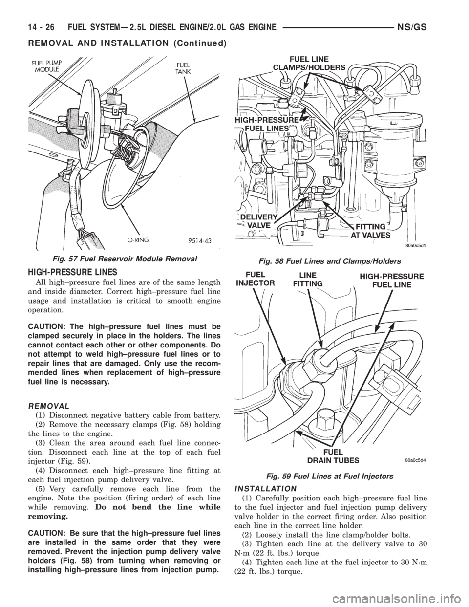
(2) Remove the necessary clamps (Fig. 58) holding
the lines to the engine.
(3) Clean the area around each fuel line connec-
tion. Disconnect each line at the top of each fuel
injector (Fig. 59).
(4) Disconnect each high±pressure line fitting at
each fuel injection pump delivery valve.
(5) Very carefully remove each line from the
engine. Note the position (firing order) of each line
while removing.Do not bend the line while
removing.
CAUTION: Be sure that the high±pressure fuel lines
are installed in the same order that they were
removed. Prevent the injection pump delivery valve
holders (Fig. 58) from turning when removing or
installing high±pressure lines from injection pump.
INSTALLATION
(1) Carefully position each high±pressure fuel line
to the fuel injector and fuel injection pump delivery
valve holder in the correct firing order. Also position
each line in the correct line holder.
(2) Loosely install the line clamp/holder bolts.
(3) Tighten each line at the delivery valve to 30
N´m (22 ft. lbs.) torque.
(4) Tighten each line at the fuel injector to 30 N´m
(22 ft. lbs.) torque.
Fig. 57 Fuel Reservoir Module RemovalFig. 58 Fuel Lines and Clamps/Holders
Fig. 59 Fuel Lines at Fuel Injectors
14 - 26 FUEL SYSTEMÐ2.5L DIESEL ENGINE/2.0L GAS ENGINENS/GS
REMOVAL AND INSTALLATION (Continued)
Page 1398 of 1938
FUEL LEVEL SENSORÐ2.0L ENGINE
Refer to the Fuel Pump Inlet Strainer for the 2.4/
3.0/3.3/3.8L engines under Removal and Installation
in the Fuel Delivery System section of group 14 for
more information.
FUEL TANKÐ2.0L ENGINE
Refer to the Fuel Tank for the 2.4/3.0/3.3/3.8L
engines under Removal and Installation in the Fuel
Delivery System section of group 14 for more infor-
mation.
FUEL INJECTORS
REMOVAL
(1) Disconnect negative cable from battery.
(2) Release fuel system pressure. Refer to Fuel
System Pressure Release procedure in this section.
(3) Disconnect fuel supply tube from rail. Refer to
Quick-Connect Fittings in the Fuel Delivery section
of this group.
(4) Disconnect electrical connectors from fuel injec-
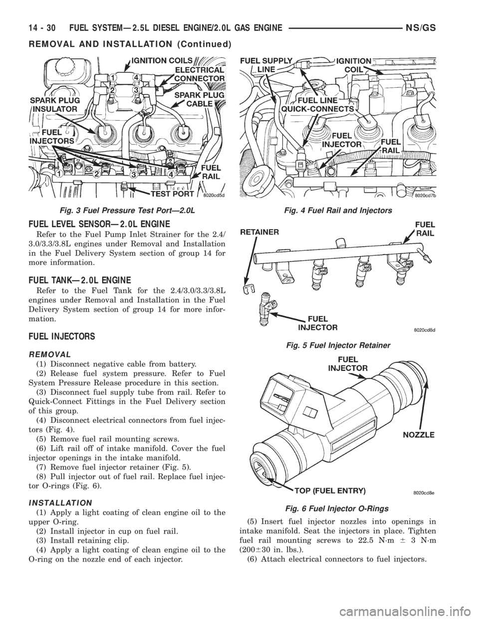
tors (Fig. 4).
(5) Remove fuel rail mounting screws.
(6) Lift rail off of intake manifold. Cover the fuel
injector openings in the intake manifold.
(7) Remove fuel injector retainer (Fig. 5).
(8) Pull injector out of fuel rail. Replace fuel injec-
tor O-rings (Fig. 6).
INSTALLATION
(1) Apply a light coating of clean engine oil to the
upper O-ring.
(2) Install injector in cup on fuel rail.
(3) Install retaining clip.
(4) Apply a light coating of clean engine oil to the
O-ring on the nozzle end of each injector.(5) Insert fuel injector nozzles into openings in
intake manifold. Seat the injectors in place. Tighten
fuel rail mounting screws to 22.5 N´m63 N´m
(200630 in. lbs.).
(6) Attach electrical connectors to fuel injectors.
Fig. 3 Fuel Pressure Test PortÐ2.0LFig. 4 Fuel Rail and Injectors
Fig. 5 Fuel Injector Retainer
Fig. 6 Fuel Injector O-Rings
14 - 30 FUEL SYSTEMÐ2.5L DIESEL ENGINE/2.0L GAS ENGINENS/GS
REMOVAL AND INSTALLATION (Continued)