Page 1349 of 1938
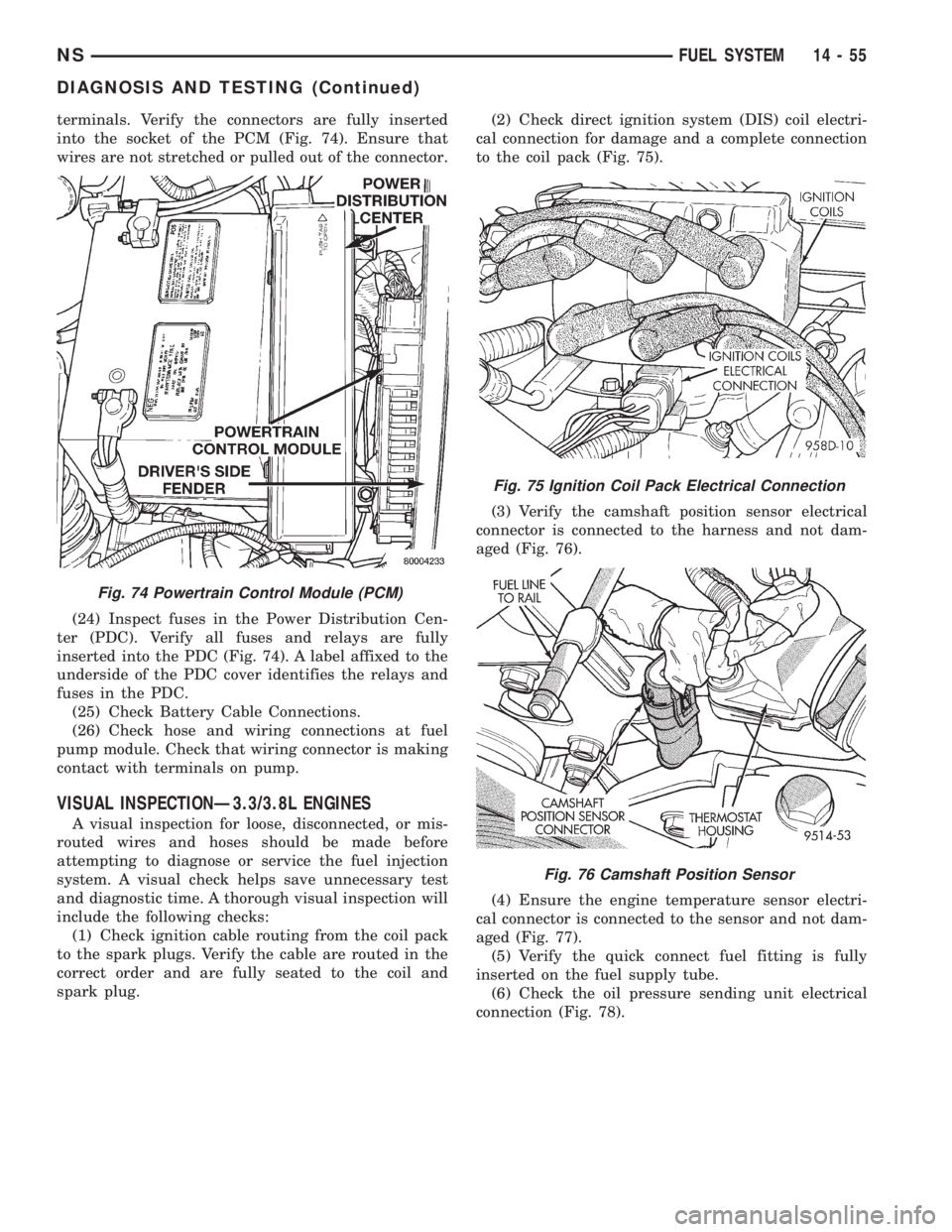
terminals. Verify the connectors are fully inserted
into the socket of the PCM (Fig. 74). Ensure that
wires are not stretched or pulled out of the connector.
(24) Inspect fuses in the Power Distribution Cen-
ter (PDC). Verify all fuses and relays are fully
inserted into the PDC (Fig. 74). A label affixed to the
underside of the PDC cover identifies the relays and
fuses in the PDC.
(25) Check Battery Cable Connections.
(26) Check hose and wiring connections at fuel
pump module. Check that wiring connector is making
contact with terminals on pump.
VISUAL INSPECTIONÐ3.3/3.8L ENGINES
A visual inspection for loose, disconnected, or mis-
routed wires and hoses should be made before
attempting to diagnose or service the fuel injection
system. A visual check helps save unnecessary test
and diagnostic time. A thorough visual inspection will
include the following checks:
(1) Check ignition cable routing from the coil pack
to the spark plugs. Verify the cable are routed in the
correct order and are fully seated to the coil and
spark plug.(2) Check direct ignition system (DIS) coil electri-
cal connection for damage and a complete connection
to the coil pack (Fig. 75).
(3) Verify the camshaft position sensor electrical
connector is connected to the harness and not dam-
aged (Fig. 76).
(4) Ensure the engine temperature sensor electri-
cal connector is connected to the sensor and not dam-
aged (Fig. 77).
(5) Verify the quick connect fuel fitting is fully
inserted on the fuel supply tube.
(6) Check the oil pressure sending unit electrical
connection (Fig. 78).
Fig. 74 Powertrain Control Module (PCM)
Fig. 75 Ignition Coil Pack Electrical Connection
Fig. 76 Camshaft Position Sensor
NSFUEL SYSTEM 14 - 55
DIAGNOSIS AND TESTING (Continued)
Page 1353 of 1938
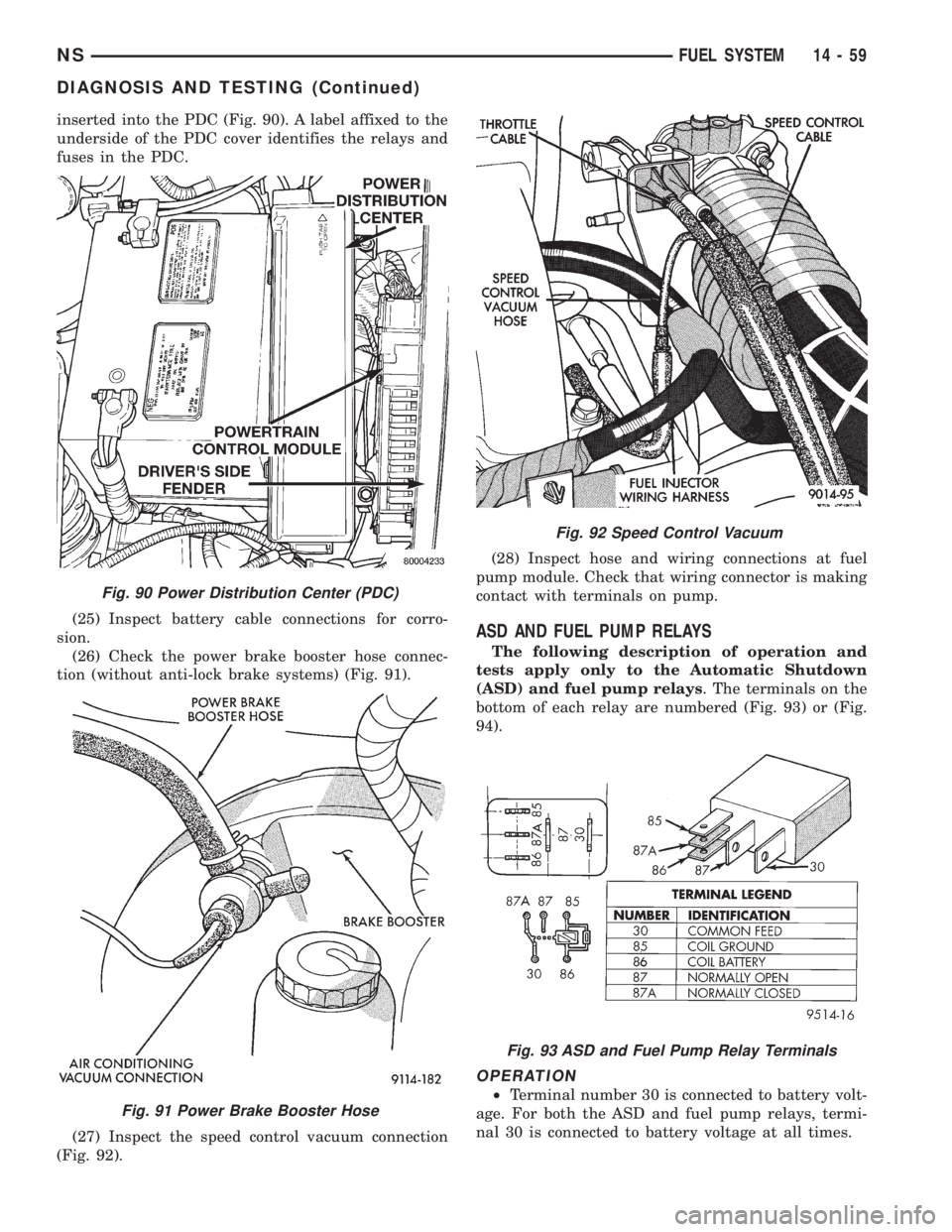
inserted into the PDC (Fig. 90). A label affixed to the
underside of the PDC cover identifies the relays and
fuses in the PDC.
(25) Inspect battery cable connections for corro-
sion.
(26) Check the power brake booster hose connec-
tion (without anti-lock brake systems) (Fig. 91).
(27) Inspect the speed control vacuum connection
(Fig. 92).(28) Inspect hose and wiring connections at fuel
pump module. Check that wiring connector is making
contact with terminals on pump.
ASD AND FUEL PUMP RELAYS
The following description of operation and
tests apply only to the Automatic Shutdown
(ASD) and fuel pump relays. The terminals on the
bottom of each relay are numbered (Fig. 93) or (Fig.
94).
OPERATION
²Terminal number 30 is connected to battery volt-
age. For both the ASD and fuel pump relays, termi-
nal 30 is connected to battery voltage at all times.
Fig. 90 Power Distribution Center (PDC)
Fig. 91 Power Brake Booster Hose
Fig. 92 Speed Control Vacuum
Fig. 93 ASD and Fuel Pump Relay Terminals
NSFUEL SYSTEM 14 - 59
DIAGNOSIS AND TESTING (Continued)
Page 1358 of 1938
REMOVAL AND INSTALLATION
THROTTLE BODY
REMOVAL
(1) Disconnect negative cable from battery cable.
(2) Remove air inlet to throttle body hose clamp.
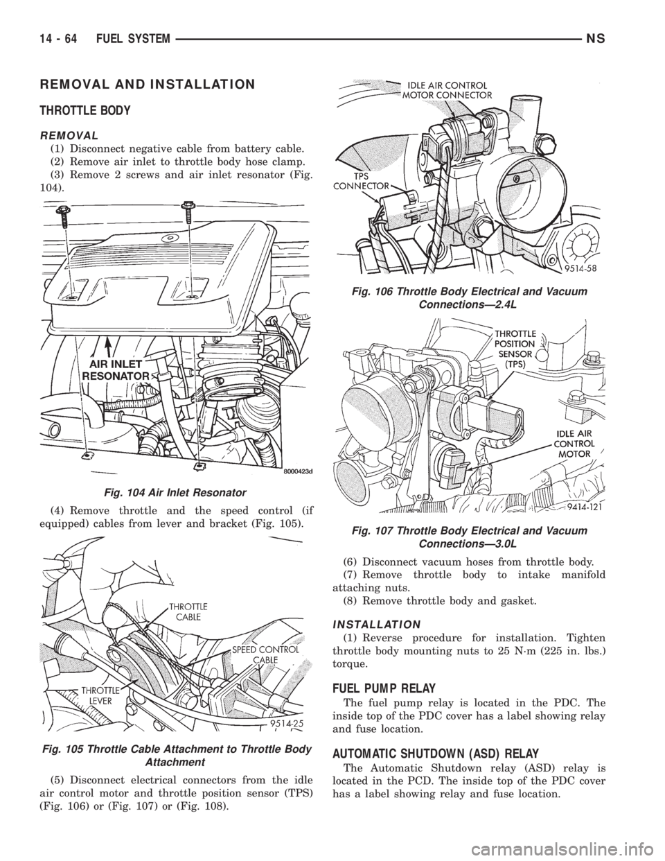
(3) Remove 2 screws and air inlet resonator (Fig.
104).
(4) Remove throttle and the speed control (if
equipped) cables from lever and bracket (Fig. 105).
(5) Disconnect electrical connectors from the idle
air control motor and throttle position sensor (TPS)
(Fig. 106) or (Fig. 107) or (Fig. 108).(6) Disconnect vacuum hoses from throttle body.
(7) Remove throttle body to intake manifold
attaching nuts.
(8) Remove throttle body and gasket.
INSTALLATION
(1) Reverse procedure for installation. Tighten
throttle body mounting nuts to 25 N´m (225 in. lbs.)
torque.
FUEL PUMP RELAY
The fuel pump relay is located in the PDC. The
inside top of the PDC cover has a label showing relay
and fuse location.
AUTOMATIC SHUTDOWN (ASD) RELAY
The Automatic Shutdown relay (ASD) relay is
located in the PCD. The inside top of the PDC cover
has a label showing relay and fuse location.
Fig. 104 Air Inlet Resonator
Fig. 105 Throttle Cable Attachment to Throttle Body
Attachment
Fig. 106 Throttle Body Electrical and Vacuum
ConnectionsÐ2.4L
Fig. 107 Throttle Body Electrical and Vacuum
ConnectionsÐ3.0L
14 - 64 FUEL SYSTEMNS
Page 1359 of 1938
THROTTLE POSITION SENSOR
REMOVAL
(1) Disconnect negative cable from battery.
(2) Remove electrical connector from throttle posi-
tion sensor.
(3) Remove throttle position sensor mounting
screws.
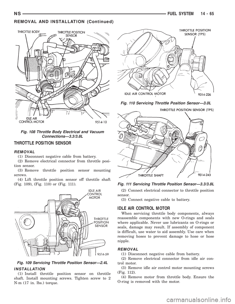
(4) Lift throttle position sensor off throttle shaft
(Fig. 109), (Fig. 110) or (Fig. 111).
INSTALLATION
(1) Install throttle position sensor on throttle
shaft. Install mounting screws. Tighten screw to 2
N´m (17 in. lbs.) torque.(2) Connect electrical connector to throttle position
sensor.
(3) Connect negative cable to battery.
IDLE AIR CONTROL MOTOR
When servicing throttle body components, always
reassemble components with new O-rings and seals
where applicable. Never use lubricants on O-rings or
seals, damage may result. If assembly of component
is difficult, use water to aid assembly. Use care when
removing hoses to prevent damage to hose or hose
nipple.
REMOVAL
(1) Disconnect negative cable from battery.
(2) Remove electrical connector from idle air con-
trol motor.
(3) Remove idle air control motor mounting screws
(Fig. 112).
(4) Remove motor from throttle body. Ensure the
O-ring is removed with the motor.
Fig. 108 Throttle Body Electrical and Vacuum
ConnectionsÐ3.3/3.8L
Fig. 109 Servicing Throttle Position SensorÐ2.4L
Fig. 110 Servicing Throttle Position SensorÐ3.0L
Fig. 111 Servicing Throttle Position SensorÐ3.3/3.8L
NSFUEL SYSTEM 14 - 65
REMOVAL AND INSTALLATION (Continued)
Page 1360 of 1938
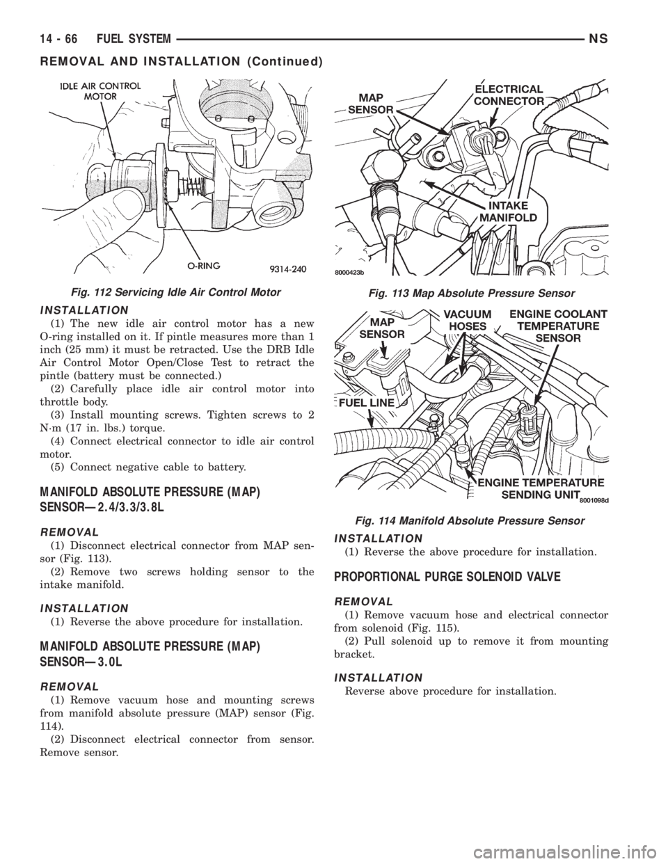
INSTALLATION
(1) The new idle air control motor has a new
O-ring installed on it. If pintle measures more than 1
inch (25 mm) it must be retracted. Use the DRB Idle
Air Control Motor Open/Close Test to retract the
pintle (battery must be connected.)
(2) Carefully place idle air control motor into
throttle body.
(3) Install mounting screws. Tighten screws to 2
N´m (17 in. lbs.) torque.
(4) Connect electrical connector to idle air control
motor.
(5) Connect negative cable to battery.
MANIFOLD ABSOLUTE PRESSURE (MAP)
SENSORÐ2.4/3.3/3.8L
REMOVAL
(1) Disconnect electrical connector from MAP sen-
sor (Fig. 113).
(2) Remove two screws holding sensor to the
intake manifold.
INSTALLATION
(1) Reverse the above procedure for installation.
MANIFOLD ABSOLUTE PRESSURE (MAP)
SENSORÐ3.0L
REMOVAL
(1) Remove vacuum hose and mounting screws
from manifold absolute pressure (MAP) sensor (Fig.
114).
(2) Disconnect electrical connector from sensor.
Remove sensor.
INSTALLATION
(1) Reverse the above procedure for installation.
PROPORTIONAL PURGE SOLENOID VALVE
REMOVAL
(1) Remove vacuum hose and electrical connector
from solenoid (Fig. 115).
(2) Pull solenoid up to remove it from mounting
bracket.
INSTALLATION
Reverse above procedure for installation.
Fig. 112 Servicing Idle Air Control MotorFig. 113 Map Absolute Pressure Sensor
Fig. 114 Manifold Absolute Pressure Sensor
14 - 66 FUEL SYSTEMNS
REMOVAL AND INSTALLATION (Continued)
Page 1361 of 1938
POWERTRAIN CONTROL MODULE
REMOVAL
(1) Disconnect both cables from battery, negative
cable first.
(2) Remove 2 screws holding Power Distribution
Center (PDC) to bracket (Fig. 116).
(3) Remove heat shield from battery (Fig. 117).
(4) Remove nut and clamp holding battery to bat-
tery tray (Fig. 118).
(5) Remove battery from vehicle.(6) Rotate PDC toward center of vehicle to remove
from rear bracket (Fig. 119).
(7) Pull PDC rearward to remove from front
bracket. Lay PDC aside to allow access to Powertrain
Control Module (PCM).
(8) Squeeze tabs on 40-way connector. Pull connec-
tor rearward to remove from PCM (Fig. 120). Remove
both way connectors.
Fig. 115 Proportional Purge Solenoid Valve
Fig. 116 Power Distribution Center Retaining Screws
Fig. 117 Battery Heat Shield
Fig. 118 Battery Clamp
NSFUEL SYSTEM 14 - 67
REMOVAL AND INSTALLATION (Continued)
Page 1362 of 1938
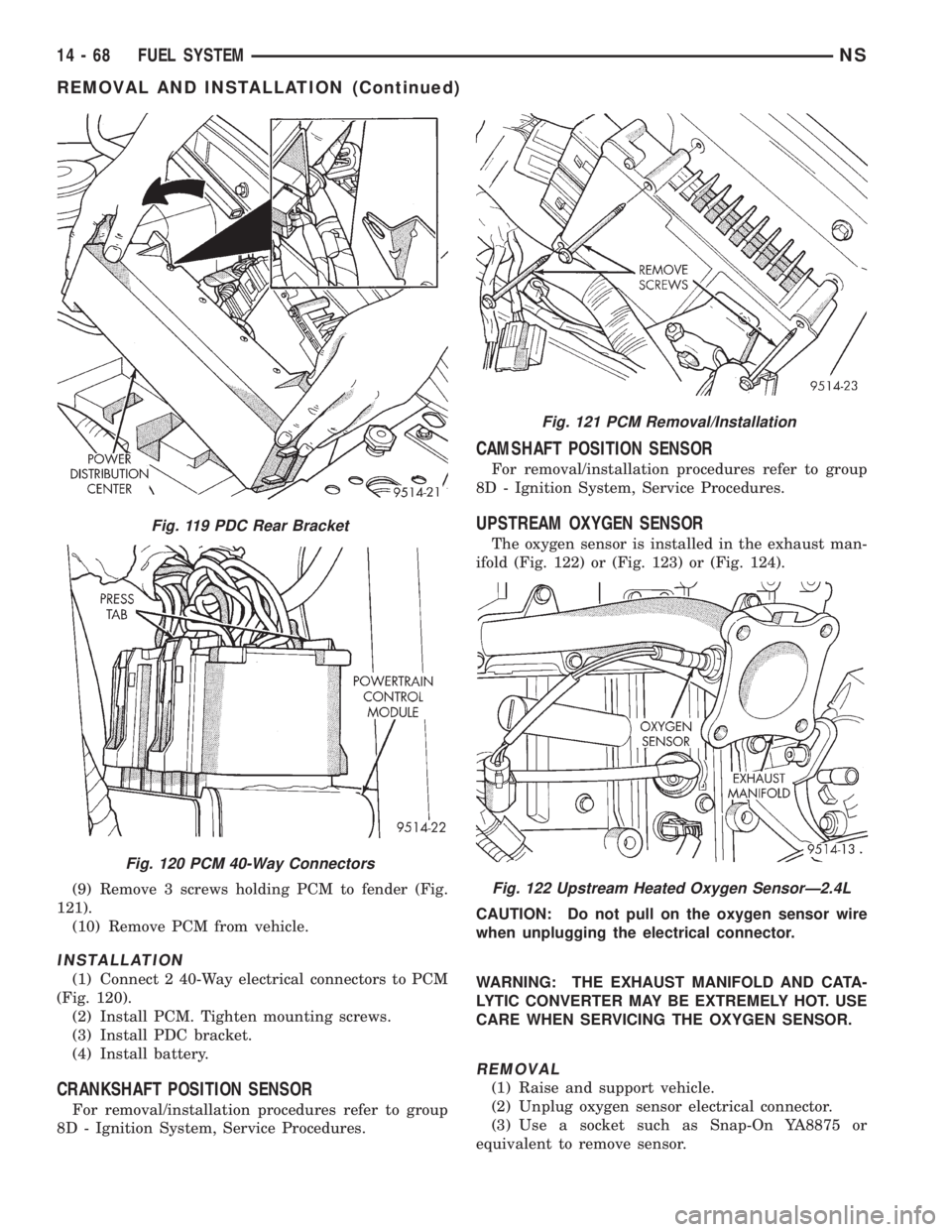
(9) Remove 3 screws holding PCM to fender (Fig.
121).
(10) Remove PCM from vehicle.
INSTALLATION
(1) Connect 2 40-Way electrical connectors to PCM
(Fig. 120).
(2) Install PCM. Tighten mounting screws.
(3) Install PDC bracket.
(4) Install battery.
CRANKSHAFT POSITION SENSOR
For removal/installation procedures refer to group
8D - Ignition System, Service Procedures.
CAMSHAFT POSITION SENSOR
For removal/installation procedures refer to group
8D - Ignition System, Service Procedures.
UPSTREAM OXYGEN SENSOR
The oxygen sensor is installed in the exhaust man-
ifold (Fig. 122) or (Fig. 123) or (Fig. 124).
CAUTION: Do not pull on the oxygen sensor wire
when unplugging the electrical connector.
WARNING: THE EXHAUST MANIFOLD AND CATA-
LYTIC CONVERTER MAY BE EXTREMELY HOT. USE
CARE WHEN SERVICING THE OXYGEN SENSOR.
REMOVAL
(1) Raise and support vehicle.
(2) Unplug oxygen sensor electrical connector.
(3) Use a socket such as Snap-On YA8875 or
equivalent to remove sensor.
Fig. 119 PDC Rear Bracket
Fig. 120 PCM 40-Way Connectors
Fig. 121 PCM Removal/Installation
Fig. 122 Upstream Heated Oxygen SensorÐ2.4L
14 - 68 FUEL SYSTEMNS
REMOVAL AND INSTALLATION (Continued)
Page 1376 of 1938
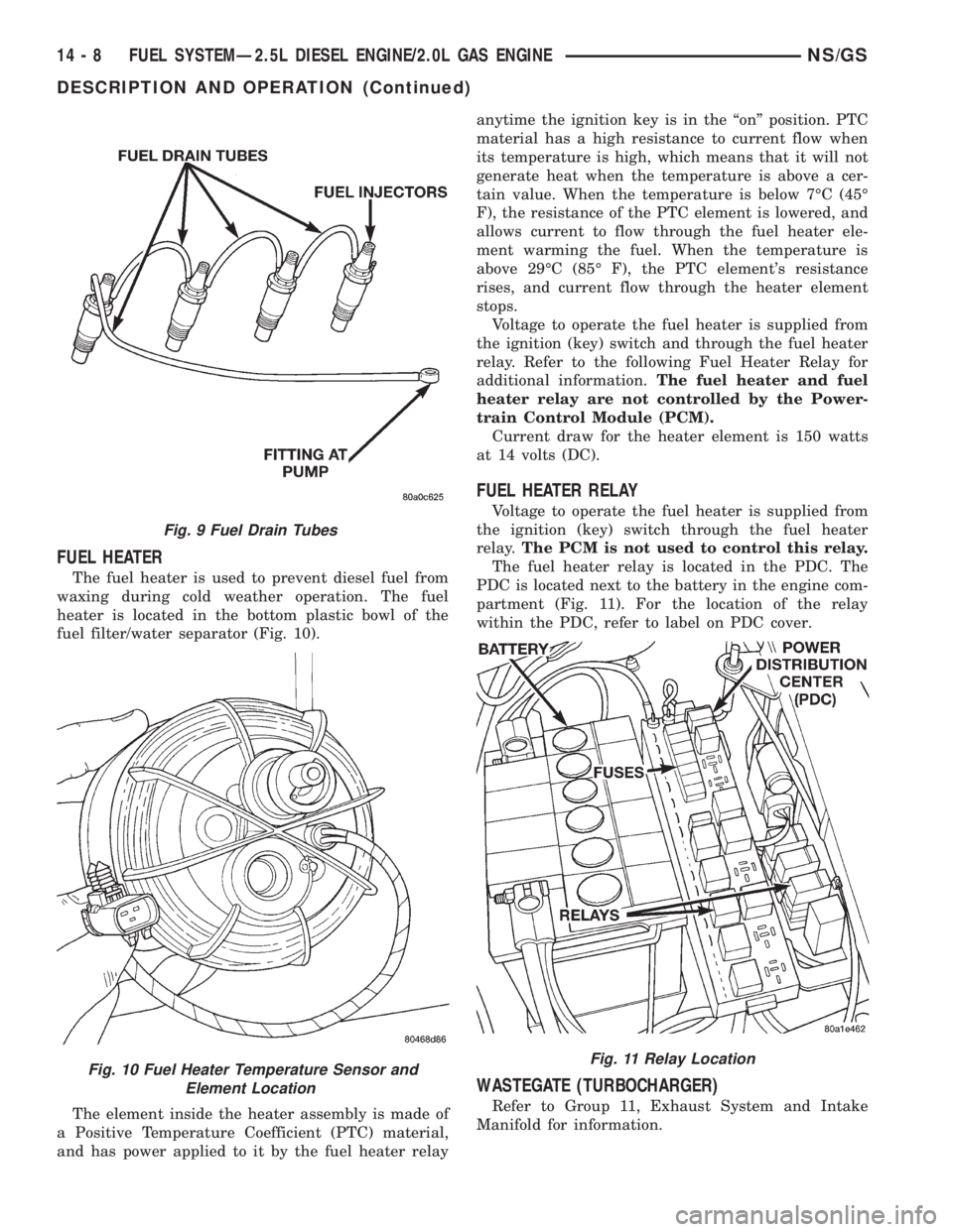
FUEL HEATER
The fuel heater is used to prevent diesel fuel from
waxing during cold weather operation. The fuel
heater is located in the bottom plastic bowl of the
fuel filter/water separator (Fig. 10).
The element inside the heater assembly is made of
a Positive Temperature Coefficient (PTC) material,
and has power applied to it by the fuel heater relayanytime the ignition key is in the ªonº position. PTC
material has a high resistance to current flow when
its temperature is high, which means that it will not
generate heat when the temperature is above a cer-
tain value. When the temperature is below 7ÉC (45É
F), the resistance of the PTC element is lowered, and
allows current to flow through the fuel heater ele-
ment warming the fuel. When the temperature is
above 29ÉC (85É F), the PTC element's resistance
rises, and current flow through the heater element
stops.
Voltage to operate the fuel heater is supplied from
the ignition (key) switch and through the fuel heater
relay. Refer to the following Fuel Heater Relay for
additional information.The fuel heater and fuel
heater relay are not controlled by the Power-
train Control Module (PCM).
Current draw for the heater element is 150 watts
at 14 volts (DC).
FUEL HEATER RELAY
Voltage to operate the fuel heater is supplied from
the ignition (key) switch through the fuel heater
relay.The PCM is not used to control this relay.
The fuel heater relay is located in the PDC. The
PDC is located next to the battery in the engine com-
partment (Fig. 11). For the location of the relay
within the PDC, refer to label on PDC cover.
WASTEGATE (TURBOCHARGER)
Refer to Group 11, Exhaust System and Intake
Manifold for information.
Fig. 9 Fuel Drain Tubes
Fig. 10 Fuel Heater Temperature Sensor and
Element LocationFig. 11 Relay Location
14 - 8 FUEL SYSTEMÐ2.5L DIESEL ENGINE/2.0L GAS ENGINENS/GS
DESCRIPTION AND OPERATION (Continued)