1996 CHRYSLER VOYAGER check engine
[x] Cancel search: check enginePage 1390 of 1938
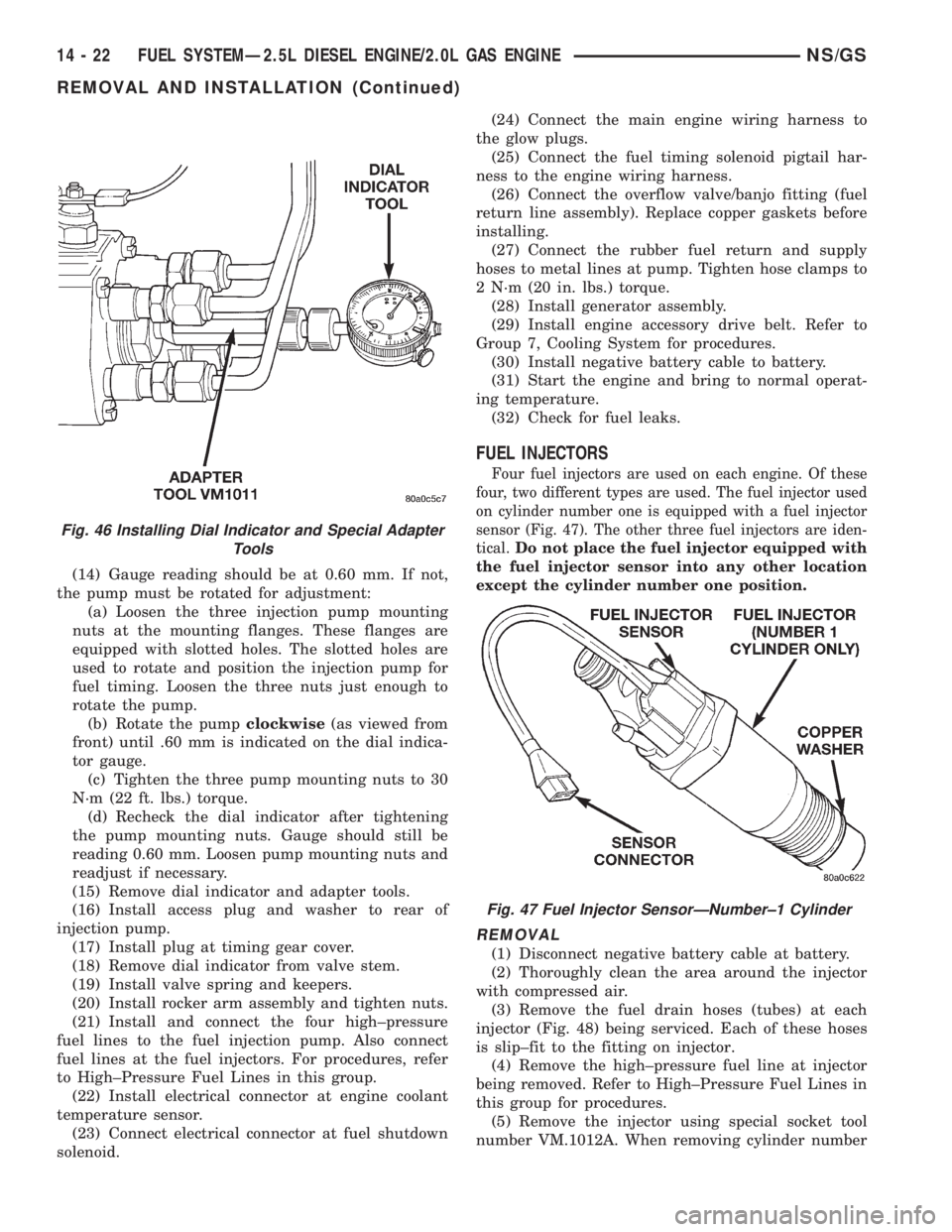
(14) Gauge reading should be at 0.60 mm. If not,
the pump must be rotated for adjustment:
(a) Loosen the three injection pump mounting
nuts at the mounting flanges. These flanges are
equipped with slotted holes. The slotted holes are
used to rotate and position the injection pump for
fuel timing. Loosen the three nuts just enough to
rotate the pump.
(b) Rotate the pumpclockwise(as viewed from
front) until .60 mm is indicated on the dial indica-
tor gauge.
(c) Tighten the three pump mounting nuts to 30
N´m (22 ft. lbs.) torque.
(d) Recheck the dial indicator after tightening
the pump mounting nuts. Gauge should still be
reading 0.60 mm. Loosen pump mounting nuts and
readjust if necessary.
(15) Remove dial indicator and adapter tools.
(16) Install access plug and washer to rear of
injection pump.
(17) Install plug at timing gear cover.
(18) Remove dial indicator from valve stem.
(19) Install valve spring and keepers.
(20) Install rocker arm assembly and tighten nuts.
(21) Install and connect the four high±pressure
fuel lines to the fuel injection pump. Also connect
fuel lines at the fuel injectors. For procedures, refer
to High±Pressure Fuel Lines in this group.
(22) Install electrical connector at engine coolant
temperature sensor.
(23) Connect electrical connector at fuel shutdown
solenoid.(24) Connect the main engine wiring harness to
the glow plugs.
(25) Connect the fuel timing solenoid pigtail har-
ness to the engine wiring harness.
(26) Connect the overflow valve/banjo fitting (fuel
return line assembly). Replace copper gaskets before
installing.
(27) Connect the rubber fuel return and supply
hoses to metal lines at pump. Tighten hose clamps to
2 N´m (20 in. lbs.) torque.
(28) Install generator assembly.
(29) Install engine accessory drive belt. Refer to
Group 7, Cooling System for procedures.
(30) Install negative battery cable to battery.
(31) Start the engine and bring to normal operat-
ing temperature.
(32) Check for fuel leaks.
FUEL INJECTORS
Four fuel injectors are used on each engine. Of these
four, two different types are used. The fuel injector used
on cylinder number one is equipped with a fuel injector
sensor (Fig. 47). The other three fuel injectors are iden-
tical.
Do not place the fuel injector equipped with
the fuel injector sensor into any other location
except the cylinder number one position.
REMOVAL
(1) Disconnect negative battery cable at battery.
(2) Thoroughly clean the area around the injector
with compressed air.
(3) Remove the fuel drain hoses (tubes) at each
injector (Fig. 48) being serviced. Each of these hoses
is slip±fit to the fitting on injector.
(4) Remove the high±pressure fuel line at injector
being removed. Refer to High±Pressure Fuel Lines in
this group for procedures.
(5) Remove the injector using special socket tool
number VM.1012A. When removing cylinder number
Fig. 46 Installing Dial Indicator and Special Adapter
Tools
Fig. 47 Fuel Injector SensorÐNumber±1 Cylinder
14 - 22 FUEL SYSTEMÐ2.5L DIESEL ENGINE/2.0L GAS ENGINENS/GS
REMOVAL AND INSTALLATION (Continued)
Page 1393 of 1938
fuel fitting. Refer to Tube/Fitting Assembly in the
Fuel Delivery section of this Group.
(7) Attach filler line to filler tube. Pull on connec-
tor to make sure of connection.
(8) Fill fuel tank, replace cap, and connect battery
negative cable.
FUEL RESERVOIR MODULE
REMOVAL
WARNING: THE FUEL RESERVOIR OF THE FUEL
MODULE DOES NOT EMPTY OUT WHEN THE TANK
IS DRAINED. THE FUEL IN THE RESERVOIR WILL
SPILL OUT WHEN THE MODULE IS REMOVED.
(1) Disconnect negative cable from battery.
(2) Insert fuel siphon hose into fuel filler neck and
push it into the tank.
(3) Drain fuel tank dry into holding tank or a
properly labeleddieselsafety container.
(4) Raise vehicle on hoist.
(5) Use a transmission jack to support the fuel
tank. Remove bolts from fuel tank straps. Lower
tank slightly.
(6) Clean area around fuel reservoir module and
tank to keep dirt and foreign material out of tank.
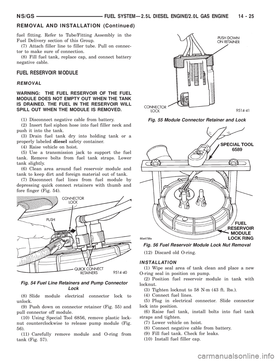
(7) Disconnect fuel lines from fuel module by
depressing quick connect retainers with thumb and
fore finger (Fig. 54).
(8) Slide module electrical connector lock to
unlock.
(9) Push down on connector retainer (Fig. 55) and
pull connector off module.
(10) Using Special Tool 6856, remove plastic lock-
nut counterclockwise to release pump module (Fig.
56).
(11) Carefully remove module and O-ring from
tank (Fig. 57).(12) Discard old O-ring.
INSTALLATION
(1) Wipe seal area of tank clean and place a new
O-ring seal in position on pump.
(2) Position fuel reservoir module in tank with
locknut.
(3) Tighten locknut to 58 N´m (43 ft. lbs.).
(4) Connect fuel lines.
(5) Plug in electrical connector. Slide connector
lock into position.
(6) Raise fuel tank, install bolts into fuel tank
straps and tighten.
(7) Lower vehicle on hoist.
(8) Connect negative cable from battery.
(9) Fill fuel tank. Check for leaks.
(10) Install fuel filler cap.
Fig. 54 Fuel Line Retainers and Pump Connector
Lock
Fig. 55 Module Connector Retainer and Lock
Fig. 56 Fuel Reservoir Module Lock Nut Removal
NS/GSFUEL SYSTEMÐ2.5L DIESEL ENGINE/2.0L GAS ENGINE 14 - 25
REMOVAL AND INSTALLATION (Continued)
Page 1400 of 1938
FUEL INJECTION SYSTEMÐ2.0L ENGINE
INDEX
page page
GENERAL INFORMATION
INTRODUCTIONÐ2.0L ENGINE............ 32
MODES OF OPERATIONÐ2.0L ENGINE..... 32
DESCRIPTION AND OPERATION
AIR CONDITIONING (A/C) RELAYÐPCM
OUTPUTÐ2.0L ENGINE................ 35
AIR CONDITIONING PRESSURE
TRANSDUCERÐPCM INPUTÐ
2.0L ENGINE......................... 33
AIR CONDITIONING SWITCH SENSEÐ
PCM INPUTÐ2.0L ENGINE.............. 33
AUTOMATIC SHUTDOWN (ASD) SENSEÐ
PCM INPUTÐ2.0L ENGINE.............. 33
AUTOMATIC SHUTDOWN RELAYÐ
PCM OUTPUTÐ2.0L ENGINE............ 35
BATTERY VOLTAGEÐPCM INPUTÐ
2.0L ENGINE......................... 33
CAMSHAFT POSITION SENSORÐ
PCM INPUTÐ2.0L ENGINE.............. 33
CRANKSHAFT POSITION SENSORÐ
PCM INPUTÐ2.0L ENGINE.............. 33
DATA LINK CONNECTORÐPCM OUTPUTÐ
2.0L ENGINE......................... 35
ELECTRONIC EGR TRANSDUCERÐ
PCM OUTPUTÐ2.0L ENGINE............ 35
ENGINE COOLANT TEMPERATURE SENSORÐ
PCM INPUTÐ2.0L ENGINE.............. 33
FUEL INJECTORSÐPCM OUTPUTÐ
2.0L ENGINE......................... 35
FUEL PUMP RELAYÐPCM OUTPUTÐ
2.0L ENGINE......................... 35
GENERATOR FIELDÐPCM OUTPUTÐ
2.0L ENGINE......................... 35
HEATED OXYGEN SENSORÐPCM INPUTÐ
2.0L ENGINE......................... 33
IDLE AIR CONTROL MOTORÐPCM OUTPUTÐ
2.0L ENGINE......................... 35
IGNITION COILÐPCM OUTPUTÐ
2.0L ENGINE......................... 36KNOCK SENSORÐPCM INPUTÐ
2.0L ENGINE......................... 34
MALFUNCTION INDICATOR (CHECK ENGINE)
LAMPÐPCM OUTPUTÐ2.0L ENGINE...... 36
MANIFOLD ABSOLUTE PRESSURE
(MAP SENSOR)ÐPCM INPUTÐ
2.0L ENGINE......................... 34
POWERTRAIN CONTROL MODULEÐ
2.0L ENGINE......................... 33
RADIATOR FAN CONTROL MODULEÐ
PCM OUTPUTÐ2.0L ENGINE............ 36
SPEED CONTROL SOLENOIDSÐ
PCM OUTPUTÐ2.0L ENGINE............ 36
SPEED CONTROLÐPCM INPUTÐ
2.0L ENGINE......................... 34
STARTER RELAYÐPCM OUTPUTÐ
2.0L ENGINE......................... 35
SYSTEM DIAGNOSISÐ2.0L ENGINE........ 33
TACHOMETERÐPCM OUTPUTÐ
2.0L ENGINE......................... 36
THROTTLE BODYÐ2.0L ENGINE.......... 36
THROTTLE POSITION SENSOR/ IDLE AIR
CONTROL MOTORÐPCM INPUTÐ
2.0L ENGINE......................... 35
DIAGNOSIS AND TESTING
ASD AND FUEL PUMP RELAYSÐ
2.0L ENGINE......................... 39
CAMSHAFT AND CRANKSHAFT
POSITION SENSOR................... 40
ENGINE COOLANT TEMPERATURE
SENSOR............................ 40
KNOCK SENSORÐ2.0L ENGINE........... 40
MANIFOLD ABSOLUTE PRESSURE
(MAP) SENSORÐ2.0L ENGINE........... 39
THROTTLE BODY MINIMUM AIR FLOW..... 41
THROTTLE POSITION SENSOR........... 40
VISUAL INSPECTIONÐSOHC............. 36
SPECIFICATIONS
TORQUE............................. 42
GENERAL INFORMATION
INTRODUCTIONÐ2.0L ENGINE
Refer to the Introduction for 2.4/3.0/3.3/3.8L
engines under General Information in the Fuel Injec-
tion System section of group 14 for more information.
MODES OF OPERATIONÐ2.0L ENGINE
Refer to the Modes of Operation for 2.4/3.0/3.3/3.8L
engines under General Information in the Fuel Injec-
tion System section of group 14 for more information.
14 - 32 FUEL SYSTEMÐ2.5L DIESEL ENGINE/2.0L GAS ENGINENS/GS
Page 1404 of 1938
IGNITION COILÐPCM OUTPUTÐ2.0L ENGINE
Refer to the Ignition Coil for 2.4/3.0/3.3/3.8L
engines under Description and Operation in the Fuel
Injection System section of group 14 for more infor-
mation.
MALFUNCTION INDICATOR (CHECK ENGINE)
LAMPÐPCM OUTPUTÐ2.0L ENGINE
Refer to the Malfunction Indicator Lamp for 2.4/
3.0/3.3/3.8L engines under Description and Operation
in the Fuel Injection System section of group 14 for
more information.
RADIATOR FAN CONTROL MODULEÐPCM
OUTPUTÐ2.0L ENGINE
Refer to the Radiator Fan Control Module for 2.4/
3.0/3.3/3.8L engines under Description and Operation
in the Fuel Injection System section of group 14 for
more information.
SPEED CONTROL SOLENOIDSÐPCM OUTPUTÐ
2.0L ENGINE
Refer to the Speed Control Solenoids for 2.4/3.0/3.3/
3.8L engines under Description and Operation in the
Fuel Injection System section of group 14 for more
information.
TACHOMETERÐPCM OUTPUTÐ2.0L ENGINE
Refer to the Tachometer for 2.4/3.0/3.3/3.8L engines
under Description and Operation in the Fuel Injec-
tion System section of group 14 for more information.
THROTTLE BODYÐ2.0L ENGINE
Refer to the Throttle Body for 2.4/3.0/3.3/3.8L
engines under Description and Operation in the Fuel
Injection System section of group 14 for more infor-
mation.
DIAGNOSIS AND TESTING
VISUAL INSPECTIONÐSOHC
Before diagnosing or servicing the fuel injection
system, perform a visual inspection for loose, discon-
nected, or misrouted wires and hoses. A thorough
visual inspection that includes the following checks
saves unnecessary test and diagnostic time.
(1) Inspect the battery connections. Clean corroded
terminals.
(2) Check the 2 PCM 40-way connector for
stretched wires on pushed out terminals
(3) Open the Power Distribution Center (PDC).
Check for blown fuses. Ensure the relays and fuses
are fully seated in the PDC. A label on the underside
of the PDC cover shows the locations of each relay
and fuse.
(4) Verify the throttle cable operates freely.
(5) Check the electrical connections at the idle air
control motor and throttle position sensor.
(6) Check hose connections between the PCV
valve, vacuum port - intake manifold and the oil sep-
arator (Fig. 13).
(7) Inspect the electrical connections at the MAP
sensor/intake air temperature sensor and the (Fig.
14).
(8) Inspect the fuel injector electrical connections
(Fig. 15).
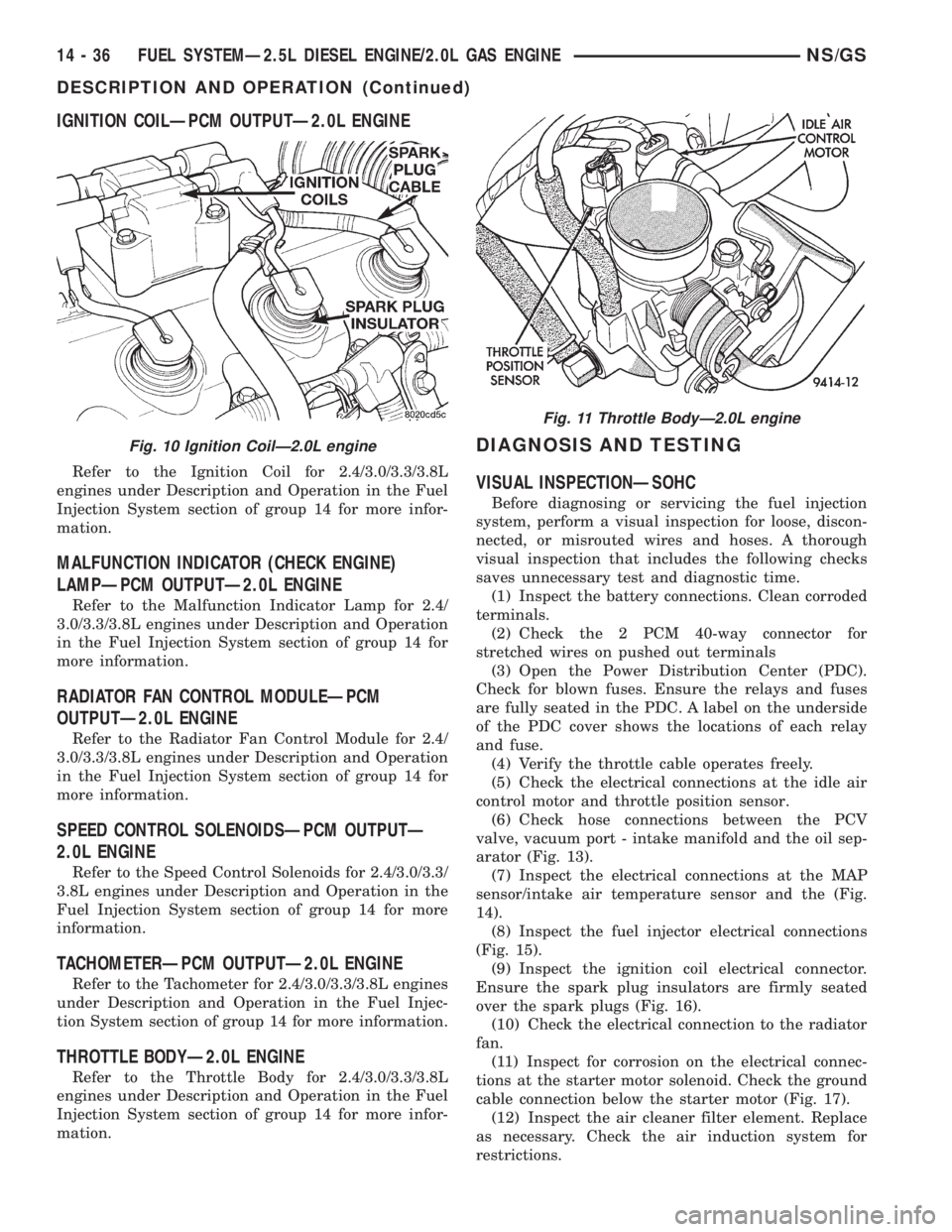
(9) Inspect the ignition coil electrical connector.
Ensure the spark plug insulators are firmly seated
over the spark plugs (Fig. 16).
(10) Check the electrical connection to the radiator
fan.
(11) Inspect for corrosion on the electrical connec-
tions at the starter motor solenoid. Check the ground
cable connection below the starter motor (Fig. 17).
(12) Inspect the air cleaner filter element. Replace
as necessary. Check the air induction system for
restrictions.
Fig. 10 Ignition CoilÐ2.0L engine
Fig. 11 Throttle BodyÐ2.0L engine
14 - 36 FUEL SYSTEMÐ2.5L DIESEL ENGINE/2.0L GAS ENGINENS/GS
DESCRIPTION AND OPERATION (Continued)
Page 1405 of 1938
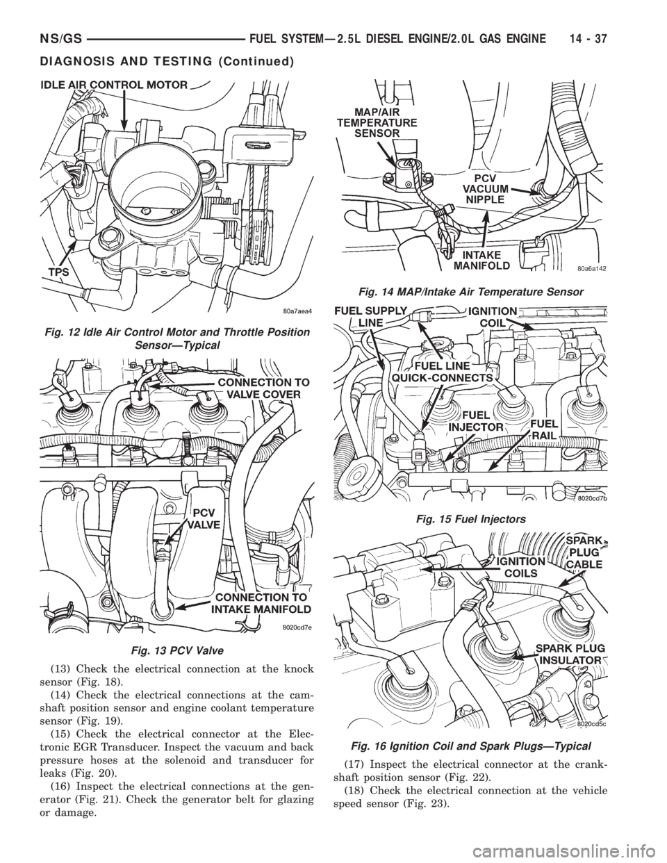
(13) Check the electrical connection at the knock
sensor (Fig. 18).
(14) Check the electrical connections at the cam-
shaft position sensor and engine coolant temperature
sensor (Fig. 19).
(15) Check the electrical connector at the Elec-
tronic EGR Transducer. Inspect the vacuum and back
pressure hoses at the solenoid and transducer for
leaks (Fig. 20).
(16) Inspect the electrical connections at the gen-
erator (Fig. 21). Check the generator belt for glazing
or damage.(17) Inspect the electrical connector at the crank-
shaft position sensor (Fig. 22).
(18) Check the electrical connection at the vehicle
speed sensor (Fig. 23).
Fig. 12 Idle Air Control Motor and Throttle Position
SensorÐTypical
Fig. 13 PCV Valve
Fig. 14 MAP/Intake Air Temperature Sensor
Fig. 15 Fuel Injectors
Fig. 16 Ignition Coil and Spark PlugsÐTypical
NS/GSFUEL SYSTEMÐ2.5L DIESEL ENGINE/2.0L GAS ENGINE 14 - 37
DIAGNOSIS AND TESTING (Continued)
Page 1406 of 1938
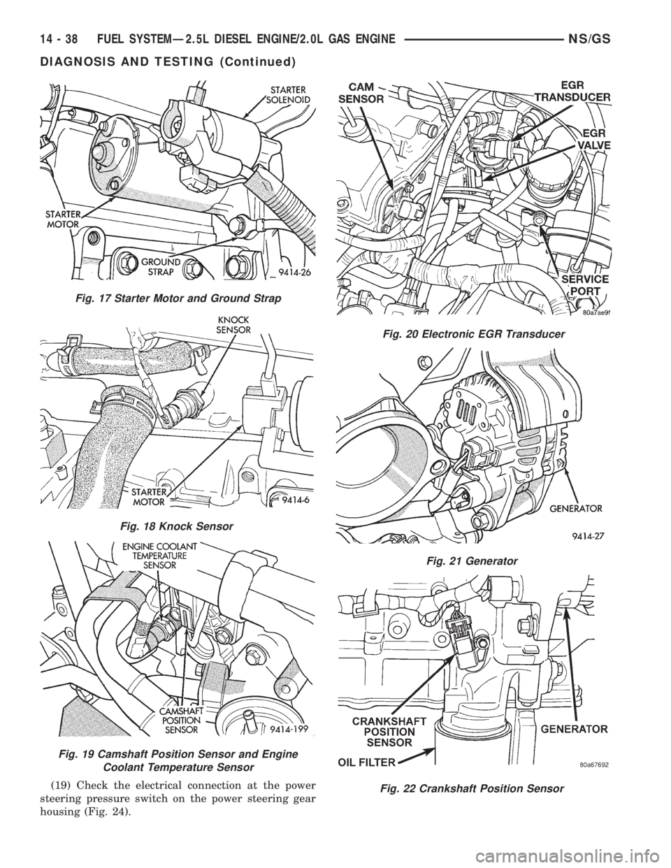
(19) Check the electrical connection at the power
steering pressure switch on the power steering gear
housing (Fig. 24).
Fig. 17 Starter Motor and Ground Strap
Fig. 18 Knock Sensor
Fig. 19 Camshaft Position Sensor and Engine
Coolant Temperature Sensor
Fig. 20 Electronic EGR Transducer
Fig. 21 Generator
Fig. 22 Crankshaft Position Sensor
14 - 38 FUEL SYSTEMÐ2.5L DIESEL ENGINE/2.0L GAS ENGINENS/GS
DIAGNOSIS AND TESTING (Continued)
Page 1407 of 1938

(20) Inspect the electrical connections at the
upstream and downstream heated oxygen sensors
(Fig. 25) and (Fig. 26).
(21) Inspect the fuel pump module electrical con-
nection at the fuel tank for corrosion or damage (Fig.27). Check for pinched, kinked or damaged fuel sup-
ply tube.
(22) Inspect the connections to the speed control
servo, if equipped. Refer to Group 8H, Vehicle Speed
Control.
(23) Inspect the connection at the battery temper-
ature sensor.
ASD AND FUEL PUMP RELAYSÐ2.0L ENGINE
Refer to the ASD and Fuel Pump Relays for 2.4/
3.0/3.3/3.8L engines under Diagnosis and Testing in
the Fuel Injection System section of group 14 for
more information.
MANIFOLD ABSOLUTE PRESSURE (MAP)
SENSORÐ2.0L ENGINE
To perform a complete test of the MAP sensor and
its circuitry, refer to the DRB scan tool and appropri-
ate Powertrain Diagnostics Procedures manual. To
test the MAP sensor only, refer to the following:
Fig. 23 Vehicle Speed Sensor
Fig. 24 Power Steering Pressure Switch
Fig. 25 Upstream Heated Oxygen Sensor
Fig. 26 Downstream Heated Oxygen Sensor
Fig. 27 Fuel Pump Module Electrical Connector
NS/GSFUEL SYSTEMÐ2.5L DIESEL ENGINE/2.0L GAS ENGINE 14 - 39
DIAGNOSIS AND TESTING (Continued)
Page 1409 of 1938
Connect the DVM between the center and sensor
ground terminal. Refer to Group 8W - Wiring Dia-
grams for correct pinout.
With the ignition switch in the ON position, check
the output voltage at the center terminal wire of the
connector. Check the output voltage at idle and at
Wide-Open-Throttle (WOT). At idle, TPS output volt-
age should be approximately 0.38 volts to 1.2 volts.
At wide open throttle, TPS output voltage should be
approximately 3.1 volts to 4.4 volts. The output volt-
age should gradually increase as the throttle plate
moves slowly from idle to WOT.
Check for spread terminals at the sensor and PCM
connections before replacing the TPS.
THROTTLE BODY MINIMUM AIR FLOW
(1) Turn ignition key to Off.
(2) D
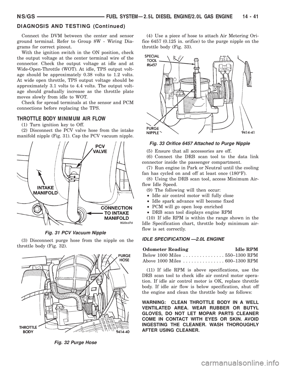
isconnect the PCV valve hose from the intake
manifold nipple (Fig. 31). Cap the PCV vacuum nipple.
(3) Disconnect purge hose from the nipple on the
throttle body (Fig. 32).(4) Use a piece of hose to attach Air Metering Ori-
fice 6457 (0.125 in. orifice) to the purge nipple on the
throttle body (Fig. 33).
(5) Ensure that all accessories are off.
(6) Connect the DRB scan tool to the data link
connector inside the passenger compartment.
(7) Run engine in Park or Neutral until the cooling
fan has cycled on and off at least once (180ÉF).
(8) Using the DRB scan tool, access Minimum Air-
flow Idle Speed.
(9) The following will then occur:
²Idle air control motor will fully close
²Idle spark advance will become fixed
²PCM will go open loop enriched
²DRB scan tool displays engine RPM
(10) If idle RPM is within the range shown in the
Idle Specification chart, throttle body minimum air-
flow is set correctly.IDLE SPECIFICATION Ð2.0L ENGINE
Odometer Reading Idle RPM
Below 1000 Miles...............550±1300 RPM
Above 1000 Miles...............600±1300 RPM
(11) If idle RPM is above specifications, use the
DRB scan tool to check idle air control motor opera-
tion. If idle air control motor is OK, replace throttle
body. If idle air flow is below specification, shut off
the engine and clean the throttle body as follows:
WARNING: CLEAN THROTTLE BODY IN A WELL
VENTILATED AREA. WEAR RUBBER OR BUTYL
GLOVES, DO NOT LET MOPAR PARTS CLEANER
COME IN CONTACT WITH EYES OR SKIN. AVOID
INGESTING THE CLEANER. WASH THOROUGHLY
AFTER USING CLEANER.
Fig. 31 PCV Vacuum Nipple
Fig. 32 Purge Hose
Fig. 33 Orifice 6457 Attached to Purge Nipple
NS/GSFUEL SYSTEMÐ2.5L DIESEL ENGINE/2.0L GAS ENGINE 14 - 41
DIAGNOSIS AND TESTING (Continued)