1996 CHRYSLER VOYAGER check engine
[x] Cancel search: check enginePage 1921 of 1938
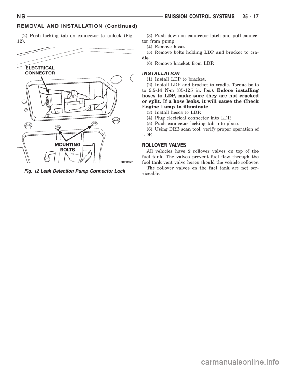
(2) Push locking tab on connector to unlock (Fig.
12).(3) Push down on connector latch and pull connec-
tor from pump.
(4) Remove hoses.
(5) Remove bolts holding LDP and bracket to cra-
dle.
(6) Remove bracket from LDP.
INSTALLATION
(1) Install LDP to bracket.
(2) Install LDP and bracket to cradle. Torque bolts
to 9.5-14 N´m (85-125 in. lbs.).Before installing
hoses to LDP, make sure they are not cracked
or split. If a hose leaks, it will cause the Check
Engine Lamp to illuminate.
(3) Install hoses to LDP.
(4) Plug electrical connector into LDP.
(5) Push connector locking tab into place.
(6) Using DRB scan tool, verify proper operation of
LDP.
ROLLOVER VALVES
All vehicles have 2 rollover valves on top of the
fuel tank. The valves prevent fuel flow through the
fuel tank vent valve hoses should the vehicle rollover.
The rollover valves on the fuel tank are not ser-
viceable.
Fig. 12 Leak Detection Pump Connector Lock
NSEMISSION CONTROL SYSTEMS 25 - 17
REMOVAL AND INSTALLATION (Continued)
Page 1923 of 1938
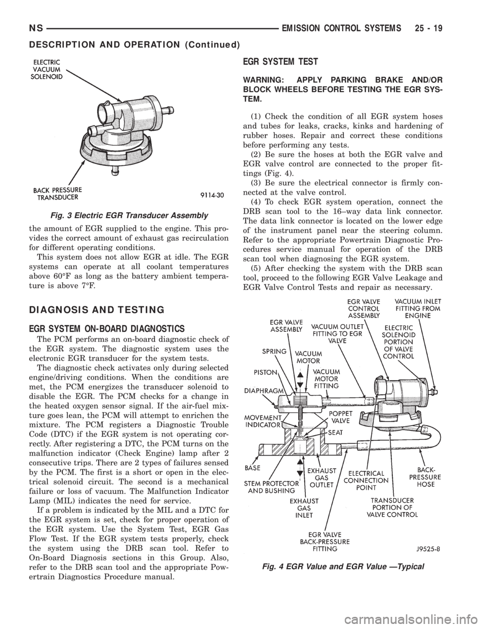
the amount of EGR supplied to the engine. This pro-
vides the correct amount of exhaust gas recirculation
for different operating conditions.
This system does not allow EGR at idle. The EGR
systems can operate at all coolant temperatures
above 60ÉF as long as the battery ambient tempera-
ture is above 7ÉF.
DIAGNOSIS AND TESTING
EGR SYSTEM ON-BOARD DIAGNOSTICS
The PCM performs an on-board diagnostic check of
the EGR system. The diagnostic system uses the
electronic EGR transducer for the system tests.
The diagnostic check activates only during selected
engine/driving conditions. When the conditions are
met, the PCM energizes the transducer solenoid to
disable the EGR. The PCM checks for a change in
the heated oxygen sensor signal. If the air-fuel mix-
ture goes lean, the PCM will attempt to enrichen the
mixture. The PCM registers a Diagnostic Trouble
Code (DTC) if the EGR system is not operating cor-
rectly. After registering a DTC, the PCM turns on the
malfunction indicator (Check Engine) lamp after 2
consecutive trips. There are 2 types of failures sensed
by the PCM. The first is a short or open in the elec-
trical solenoid circuit. The second is a mechanical
failure or loss of vacuum. The Malfunction Indicator
Lamp (MIL) indicates the need for service.
If a problem is indicated by the MIL and a DTC for
the EGR system is set, check for proper operation of
the EGR system. Use the System Test, EGR Gas
Flow Test. If the EGR system tests properly, check
the system using the DRB scan tool. Refer to
On-Board Diagnosis sections in this Group. Also,
refer to the DRB scan tool and the appropriate Pow-
ertrain Diagnostics Procedure manual.
EGR SYSTEM TEST
WARNING: APPLY PARKING BRAKE AND/OR
BLOCK WHEELS BEFORE TESTING THE EGR SYS-
TEM.
(1) Check the condition of all EGR system hoses
and tubes for leaks, cracks, kinks and hardening of
rubber hoses. Repair and correct these conditions
before performing any tests.
(2) Be sure the hoses at both the EGR valve and
EGR valve control are connected to the proper fit-
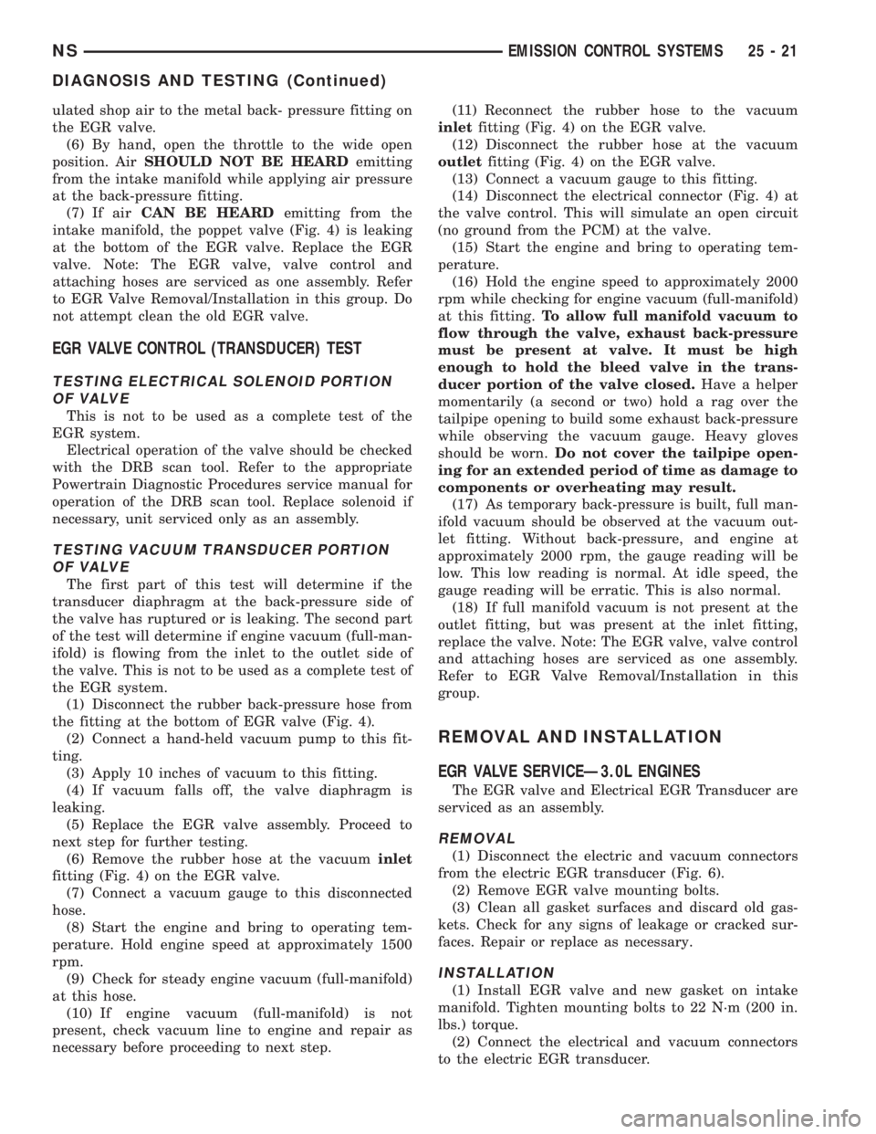
tings (Fig. 4).
(3) Be sure the electrical connector is firmly con-
nected at the valve control.
(4) To check EGR system operation, connect the
DRB scan tool to the 16±way data link connector.
The data link connector is located on the lower edge
of the instrument panel near the steering column.
Refer to the appropriate Powertrain Diagnostic Pro-
cedures service manual for operation of the DRB
scan tool when diagnosing the EGR system.
(5) After checking the system with the DRB scan
tool, proceed to the following EGR Valve Leakage and
EGR Valve Control Tests and repair as necessary.
Fig. 3 Electric EGR Transducer Assembly
Fig. 4 EGR Value and EGR Value ÐTypical
NSEMISSION CONTROL SYSTEMS 25 - 19
DESCRIPTION AND OPERATION (Continued)
Page 1924 of 1938
EGR GAS FLOW TEST
Use the following test procedure to determine if
exhaust gas is flowing through the EGR valve. It can
also be used to determine if the EGR tube is plugged,
or the system passages in the intake or exhaust man-
ifolds are plugged.
This is not to be used as a complete test of the
EGR system.
The engine must be started, running and warmed
to operating temperature for this test.
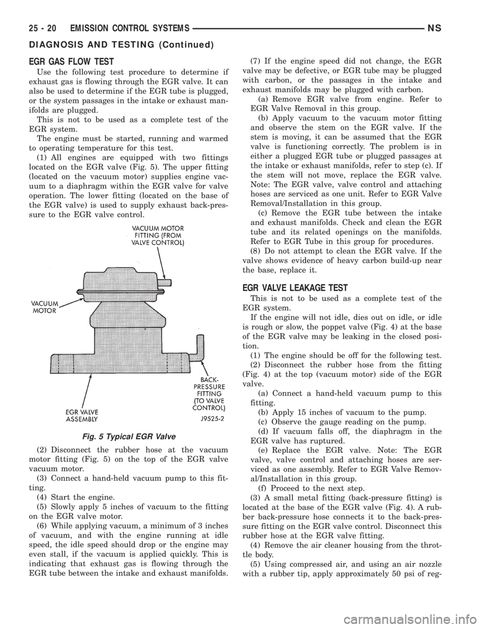
(1) All engines are equipped with two fittings
located on the EGR valve (Fig. 5). The upper fitting
(located on the vacuum motor) supplies engine vac-
uum to a diaphragm within the EGR valve for valve
operation. The lower fitting (located on the base of
the EGR valve) is used to supply exhaust back-pres-
sure to the EGR valve control.
(2) Disconnect the rubber hose at the vacuum
motor fitting (Fig. 5) on the top of the EGR valve
vacuum motor.
(3) Connect a hand-held vacuum pump to this fit-
ting.
(4) Start the engine.
(5) Slowly apply 5 inches of vacuum to the fitting
on the EGR valve motor.
(6) While applying vacuum, a minimum of 3 inches
of vacuum, and with the engine running at idle
speed, the idle speed should drop or the engine may
even stall, if the vacuum is applied quickly. This is
indicating that exhaust gas is flowing through the
EGR tube between the intake and exhaust manifolds.(7) If the engine speed did not change, the EGR
valve may be defective, or EGR tube may be plugged
with carbon, or the passages in the intake and
exhaust manifolds may be plugged with carbon.
(a) Remove EGR valve from engine. Refer to
EGR Valve Removal in this group.
(b) Apply vacuum to the vacuum motor fitting
and observe the stem on the EGR valve. If the
stem is moving, it can be assumed that the EGR
valve is functioning correctly. The problem is in
either a plugged EGR tube or plugged passages at
the intake or exhaust manifolds, refer to step (c). If
the stem will not move, replace the EGR valve.
Note: The EGR valve, valve control and attaching
hoses are serviced as one unit. Refer to EGR Valve
Removal/Installation in this group.
(c) Remove the EGR tube between the intake
and exhaust manifolds. Check and clean the EGR
tube and its related openings on the manifolds.
Refer to EGR Tube in this group for procedures.
(8) Do not attempt to clean the EGR valve. If the
valve shows evidence of heavy carbon build-up near
the base, replace it.
EGR VALVE LEAKAGE TEST
This is not to be used as a complete test of the
EGR system.
If the engine will not idle, dies out on idle, or idle
is rough or slow, the poppet valve (Fig. 4) at the base
of the EGR valve may be leaking in the closed posi-
tion.
(1) The engine should be off for the following test.
(2) Disconnect the rubber hose from the fitting
(Fig. 4) at the top (vacuum motor) side of the EGR
valve.
(a) Connect a hand-held vacuum pump to this
fitting.
(b) Apply 15 inches of vacuum to the pump.
(c) Observe the gauge reading on the pump.
(d) If vacuum falls off, the diaphragm in the
EGR valve has ruptured.
(e) Replace the EGR valve. Note: The EGR
valve, valve control and attaching hoses are ser-
viced as one assembly. Refer to EGR Valve Remov-
al/Installation in this group.
(f) Proceed to the next step.
(3) A small metal fitting (back-pressure fitting) is
located at the base of the EGR valve (Fig. 4). A rub-
ber back-pressure hose connects it to the back-pres-
sure fitting on the EGR valve control. Disconnect this
rubber hose at the EGR valve fitting.
(4) Remove the air cleaner housing from the throt-
tle body.
(5) Using compressed air, and using an air nozzle
with a rubber tip, apply approximately 50 psi of reg-
Fig. 5 Typical EGR Valve
25 - 20 EMISSION CONTROL SYSTEMSNS
DIAGNOSIS AND TESTING (Continued)
Page 1925 of 1938
ulated shop air to the metal back- pressure fitting on
the EGR valve.
(6) By hand, open the throttle to the wide open
position. AirSHOULD NOT BE HEARDemitting
from the intake manifold while applying air pressure
at the back-pressure fitting.
(7) If airCAN BE HEARDemitting from the
intake manifold, the poppet valve (Fig. 4) is leaking
at the bottom of the EGR valve. Replace the EGR
valve. Note: The EGR valve, valve control and
attaching hoses are serviced as one assembly. Refer
to EGR Valve Removal/Installation in this group. Do
not attempt clean the old EGR valve.
EGR VALVE CONTROL (TRANSDUCER) TEST
TESTING ELECTRICAL SOLENOID PORTION
OF VALVE
This is not to be used as a complete test of the
EGR system.
Electrical operation of the valve should be checked
with the DRB scan tool. Refer to the appropriate
Powertrain Diagnostic Procedures service manual for
operation of the DRB scan tool. Replace solenoid if
necessary, unit serviced only as an assembly.
TESTING VACUUM TRANSDUCER PORTION
OF VALVE
The first part of this test will determine if the
transducer diaphragm at the back-pressure side of
the valve has ruptured or is leaking. The second part
of the test will determine if engine vacuum (full-man-
ifold) is flowing from the inlet to the outlet side of
the valve. This is not to be used as a complete test of
the EGR system.
(1) Disconnect the rubber back-pressure hose from
the fitting at the bottom of EGR valve (Fig. 4).
(2) Connect a hand-held vacuum pump to this fit-
ting.
(3) Apply 10 inches of vacuum to this fitting.
(4) If vacuum falls off, the valve diaphragm is
leaking.
(5) Replace the EGR valve assembly. Proceed to
next step for further testing.
(6) Remove the rubber hose at the vacuuminlet
fitting (Fig. 4) on the EGR valve.
(7) Connect a vacuum gauge to this disconnected
hose.
(8) Start the engine and bring to operating tem-
perature. Hold engine speed at approximately 1500
rpm.
(9) Check for steady engine vacuum (full-manifold)
at this hose.
(10) If engine vacuum (full-manifold) is not
present, check vacuum line to engine and repair as
necessary before proceeding to next step.(11) Reconnect the rubber hose to the vacuum
inletfitting (Fig. 4) on the EGR valve.
(12) Disconnect the rubber hose at the vacuum
outletfitting (Fig. 4) on the EGR valve.
(13) Connect a vacuum gauge to this fitting.
(14) Disconnect the electrical connector (Fig. 4) at
the valve control. This will simulate an open circuit
(no ground from the PCM) at the valve.
(15) Start the engine and bring to operating tem-
perature.
(16) Hold the engine speed to approximately 2000
rpm while checking for engine vacuum (full-manifold)
at this fitting.To allow full manifold vacuum to
flow through the valve, exhaust back-pressure
must be present at valve. It must be high
enough to hold the bleed valve in the trans-
ducer portion of the valve closed.Have a helper
momentarily (a second or two) hold a rag over the
tailpipe opening to build some exhaust back-pressure
while observing the vacuum gauge. Heavy gloves
should be worn.Do not cover the tailpipe open-
ing for an extended period of time as damage to
components or overheating may result.
(17) As temporary back-pressure is built, full man-
ifold vacuum should be observed at the vacuum out-
let fitting. Without back-pressure, and engine at
approximately 2000 rpm, the gauge reading will be
low. This low reading is normal. At idle speed, the
gauge reading will be erratic. This is also normal.
(18) If full manifold vacuum is not present at the
outlet fitting, but was present at the inlet fitting,
replace the valve. Note: The EGR valve, valve control
and attaching hoses are serviced as one assembly.
Refer to EGR Valve Removal/Installation in this
group.
REMOVAL AND INSTALLATION
EGR VALVE SERVICEÐ3.0L ENGINES
The EGR valve and Electrical EGR Transducer are
serviced as an assembly.
REMOVAL
(1) Disconnect the electric and vacuum connectors
from the electric EGR transducer (Fig. 6).
(2) Remove EGR valve mounting bolts.
(3) Clean all gasket surfaces and discard old gas-
kets. Check for any signs of leakage or cracked sur-
faces. Repair or replace as necessary.
INSTALLATION
(1) Install EGR valve and new gasket on intake
manifold. Tighten mounting bolts to 22 N´m (200 in.
lbs.) torque.
(2) Connect the electrical and vacuum connectors
to the electric EGR transducer.
NSEMISSION CONTROL SYSTEMS 25 - 21
DIAGNOSIS AND TESTING (Continued)
Page 1926 of 1938
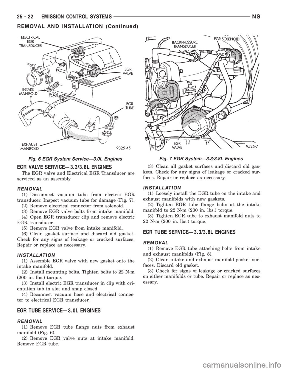
EGR VALVE SERVICEÐ3.3/3.8L ENGINES
The EGR valve and Electrical EGR Transducer are
serviced as an assembly.
REMOVAL
(1) Disconnect vacuum tube from electric EGR
transducer. Inspect vacuum tube for damage (Fig. 7).
(2) Remove electrical connector from solenoid.
(3) Remove EGR valve bolts from intake manifold.
(4) Open EGR transducer clip and remove electric
EGR transducer.
(5) Remove EGR valve from intake manifold.
(6) Clean gasket surface and discard old gasket.
Check for any signs of leakage or cracked surfaces.
Repair or replace as necessary.
INSTALLATION
(1) Assemble EGR valve with new gasket onto the
intake manifold.
(2) Install mounting bolts. Tighten bolts to 22 N´m
(200 in. lbs.) torque.
(3) Install electric EGR transducer in clip with ori-
entation tab in slot and snap closed.
(4) Reconnect vacuum hose and electrical connec-
tor to electrical EGR transducer.
EGR TUBE SERVICEÐ3.0L ENGINES
REMOVAL
(1) Remove EGR tube flange nuts from exhaust
manifold (Fig. 6).
(2) Remove EGR valve nuts at intake manifold.
Remove EGR tube.(3) Clean all gasket surfaces and discard old gas-
kets. Check for any signs of leakage or cracked sur-
faces. Repair or replace as necessary.
INSTALLATION
(1) Loosely install the EGR tube on the intake and
exhaust manifolds with new gaskets.
(2) Tighten EGR tube flange bolts at the intake
manifold to 22 N´m (200 in. lbs.) torque.
(3) Tighten EGR tube to exhaust manifold nuts to
22 N´m (200 in. lbs.) torque.
EGR TUBE SERVICEÐ3.3/3.8L ENGINES
REMOVAL
(1) Remove EGR tube attaching bolts from intake
and exhaust manifolds (Fig. 8).
(2) Clean intake and exhaust manifold gasket sur-
faces. Discard old gasket.
(3) Check for signs of leakage or cracked surfaces
on either manifolds or tube. Repair or replace as nec-
essary.
Fig. 6 EGR System ServiceÐ3.0L EnginesFig. 7 EGR SystemÐ3.3/3.8L Engines
25 - 22 EMISSION CONTROL SYSTEMSNS
REMOVAL AND INSTALLATION (Continued)
Page 1931 of 1938
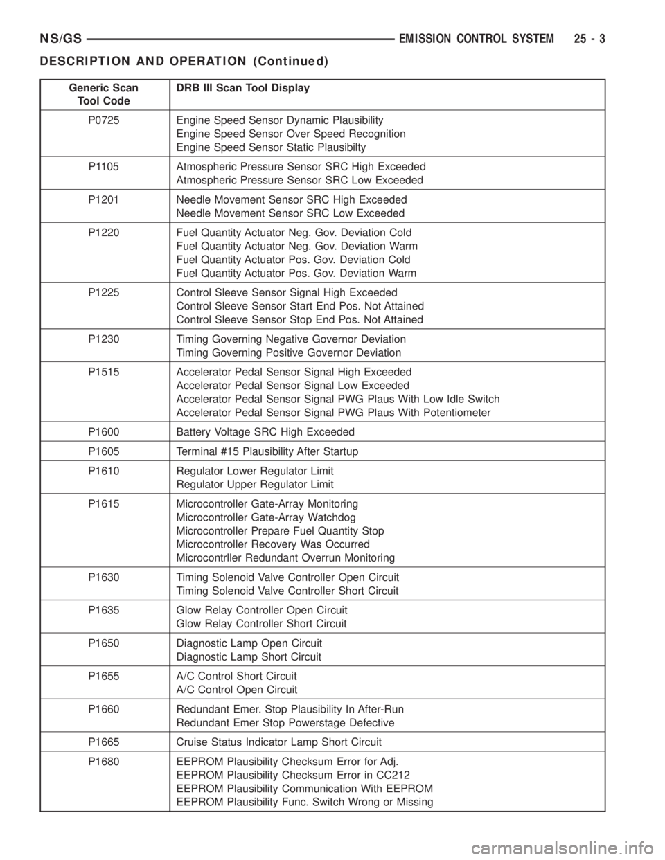
Generic Scan
Tool CodeDRB III Scan Tool Display
P0725 Engine Speed Sensor Dynamic Plausibility
Engine Speed Sensor Over Speed Recognition
Engine Speed Sensor Static Plausibilty
P1105 Atmospheric Pressure Sensor SRC High Exceeded
Atmospheric Pressure Sensor SRC Low Exceeded
P1201 Needle Movement Sensor SRC High Exceeded
Needle Movement Sensor SRC Low Exceeded
P1220 Fuel Quantity Actuator Neg. Gov. Deviation Cold
Fuel Quantity Actuator Neg. Gov. Deviation Warm
Fuel Quantity Actuator Pos. Gov. Deviation Cold
Fuel Quantity Actuator Pos. Gov. Deviation Warm
P1225 Control Sleeve Sensor Signal High Exceeded
Control Sleeve Sensor Start End Pos. Not Attained
Control Sleeve Sensor Stop End Pos. Not Attained
P1230 Timing Governing Negative Governor Deviation
Timing Governing Positive Governor Deviation
P1515 Accelerator Pedal Sensor Signal High Exceeded
Accelerator Pedal Sensor Signal Low Exceeded
Accelerator Pedal Sensor Signal PWG Plaus With Low Idle Switch
Accelerator Pedal Sensor Signal PWG Plaus With Potentiometer
P1600 Battery Voltage SRC High Exceeded
P1605 Terminal #15 Plausibility After Startup
P1610 Regulator Lower Regulator Limit
Regulator Upper Regulator Limit
P1615 Microcontroller Gate-Array Monitoring
Microcontroller Gate-Array Watchdog
Microcontroller Prepare Fuel Quantity Stop
Microcontroller Recovery Was Occurred
Microcontrller Redundant Overrun Monitoring
P1630 Timing Solenoid Valve Controller Open Circuit
Timing Solenoid Valve Controller Short Circuit
P1635 Glow Relay Controller Open Circuit
Glow Relay Controller Short Circuit
P1650 Diagnostic Lamp Open Circuit
Diagnostic Lamp Short Circuit
P1655 A/C Control Short Circuit
A/C Control Open Circuit
P1660 Redundant Emer. Stop Plausibility In After-Run
Redundant Emer Stop Powerstage Defective
P1665 Cruise Status Indicator Lamp Short Circuit
P1680 EEPROM Plausibility Checksum Error for Adj.
EEPROM Plausibility Checksum Error in CC212
EEPROM Plausibility Communication With EEPROM
EEPROM Plausibility Func. Switch Wrong or Missing
NS/GSEMISSION CONTROL SYSTEM 25 - 3
DESCRIPTION AND OPERATION (Continued)
Page 1935 of 1938
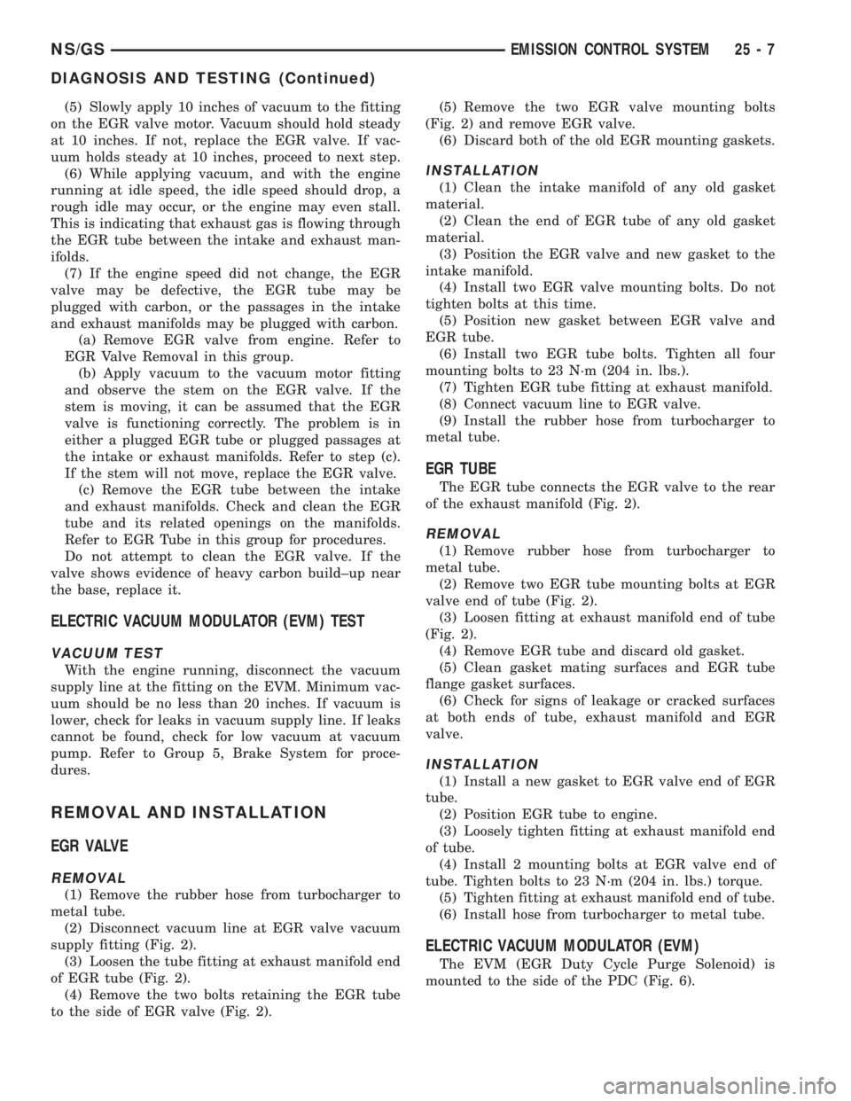
(5) Slowly apply 10 inches of vacuum to the fitting
on the EGR valve motor. Vacuum should hold steady
at 10 inches. If not, replace the EGR valve. If vac-
uum holds steady at 10 inches, proceed to next step.
(6) While applying vacuum, and with the engine
running at idle speed, the idle speed should drop, a
rough idle may occur, or the engine may even stall.
This is indicating that exhaust gas is flowing through
the EGR tube between the intake and exhaust man-
ifolds.
(7) If the engine speed did not change, the EGR
valve may be defective, the EGR tube may be
plugged with carbon, or the passages in the intake
and exhaust manifolds may be plugged with carbon.
(a) Remove EGR valve from engine. Refer to
EGR Valve Removal in this group.
(b) Apply vacuum to the vacuum motor fitting
and observe the stem on the EGR valve. If the
stem is moving, it can be assumed that the EGR
valve is functioning correctly. The problem is in
either a plugged EGR tube or plugged passages at
the intake or exhaust manifolds. Refer to step (c).
If the stem will not move, replace the EGR valve.
(c) Remove the EGR tube between the intake
and exhaust manifolds. Check and clean the EGR
tube and its related openings on the manifolds.
Refer to EGR Tube in this group for procedures.
Do not attempt to clean the EGR valve. If the
valve shows evidence of heavy carbon build±up near
the base, replace it.
ELECTRIC VACUUM MODULATOR (EVM) TEST
VACUUM TEST
With the engine running, disconnect the vacuum
supply line at the fitting on the EVM. Minimum vac-
uum should be no less than 20 inches. If vacuum is
lower, check for leaks in vacuum supply line. If leaks
cannot be found, check for low vacuum at vacuum
pump. Refer to Group 5, Brake System for proce-
dures.
REMOVAL AND INSTALLATION
EGR VALVE
REMOVAL
(1) Remove the rubber hose from turbocharger to
metal tube.
(2) Disconnect vacuum line at EGR valve vacuum
supply fitting (Fig. 2).
(3) Loosen the tube fitting at exhaust manifold end
of EGR tube (Fig. 2).
(4) Remove the two bolts retaining the EGR tube
to the side of EGR valve (Fig. 2).(5) Remove the two EGR valve mounting bolts
(Fig. 2) and remove EGR valve.
(6) Discard both of the old EGR mounting gaskets.
INSTALLATION
(1) Clean the intake manifold of any old gasket
material.
(2) Clean the end of EGR tube of any old gasket
material.
(3) Position the EGR valve and new gasket to the
intake manifold.
(4) Install two EGR valve mounting bolts. Do not
tighten bolts at this time.
(5) Position new gasket between EGR valve and
EGR tube.
(6) Install two EGR tube bolts. Tighten all four
mounting bolts to 23 N´m (204 in. lbs.).
(7) Tighten EGR tube fitting at exhaust manifold.
(8) Connect vacuum line to EGR valve.
(9) Install the rubber hose from turbocharger to
metal tube.
EGR TUBE
The EGR tube connects the EGR valve to the rear
of the exhaust manifold (Fig. 2).
REMOVAL
(1) Remove rubber hose from turbocharger to
metal tube.
(2) Remove two EGR tube mounting bolts at EGR
valve end of tube (Fig. 2).
(3) Loosen fitting at exhaust manifold end of tube
(Fig. 2).
(4) Remove EGR tube and discard old gasket.
(5) Clean gasket mating surfaces and EGR tube
flange gasket surfaces.
(6) Check for signs of leakage or cracked surfaces
at both ends of tube, exhaust manifold and EGR
valve.
INSTALLATION
(1) Install a new gasket to EGR valve end of EGR
tube.
(2) Position EGR tube to engine.
(3) Loosely tighten fitting at exhaust manifold end
of tube.
(4) Install 2 mounting bolts at EGR valve end of
tube. Tighten bolts to 23 N´m (204 in. lbs.) torque.
(5) Tighten fitting at exhaust manifold end of tube.
(6) Install hose from turbocharger to metal tube.
ELECTRIC VACUUM MODULATOR (EVM)
The EVM (EGR Duty Cycle Purge Solenoid) is
mounted to the side of the PDC (Fig. 6).
NS/GSEMISSION CONTROL SYSTEM 25 - 7
DIAGNOSIS AND TESTING (Continued)