1996 CHRYSLER VOYAGER check engine
[x] Cancel search: check enginePage 1556 of 1938
WARNING: WEAR PROTECTIVE EYEWEAR THAT
MEETS THE REQUIREMENTS OF OSHA AND ANSI
Z87.1±1968. WEAR STANDARD INDUSTRIAL RUB-
BER GLOVES.
KEEP LIGHTED CIGARETTES, SPARKS, FLAMES,
AND OTHER IGNITION SOURCES AWAY FROM THE
AREA TO PREVENT THE IGNITION OF COMBUSTI-
BLE LIQUIDS AND GASES. KEEP A CLASS (B) FIRE
EXTINGUISHER IN THE AREA WHERE THE
FLUSHER WILL BE USED.
KEEP THE AREA WELL VENTILATED.
DO NOT LET FLUSHING SOLVENT COME IN CON-
TACT WITH YOUR EYES OR SKIN: IF EYE CONTAM-
INATION OCCURS, FLUSH EYES WITH WATER FOR
15 TO 20 SECONDS. REMOVE CONTAMINATED
CLOTHING AND WASH AFFECTED SKIN WITH
SOAP AND WATER. SEEK MEDICAL ATTENTION.
COOLER FLUSH USING TOOL 6906A
(1) Remove cover plate filler plug on Tool 6906A.
Fill reservoir 1/2 to 3/4 full of fresh flushing solution.
Flushing solvents are petroleum based solutions gen-
erally used to clean automatic transmission compo-
nents.DO NOTuse solvents containing acids, water,
gasoline, or any other corrosive liquids.
(2) Reinstall filler plug on Tool 6906A.
(3) Verify pump power switch is turned OFF. Con-
nect red alligator clip to positive (+) battery post.
Connect black (-) alligator clip to a good ground.
(4) Disconnect the cooler lines at the transmission.
NOTE: When flushing transmission cooler and
lines, ALWAYS reverse flush.
(5) Connect the BLUE pressure line to the OUT-
LET (From) cooler line.
(6) Connect the CLEAR return line to the INLET
(To) cooler line
(7) Turn pump ON for two to three minutes to
flush cooler(s) and lines. Monitor pressure readings
and clear return lines. Pressure readings should sta-
bilize below 20 psi. for vehicles equipped with a sin-
gle cooler and 30 psi. for vehicles equipped with dual
coolers. If flow is intermittent or exceeds these pres-
sures, replace cooler.
(8) Turn pump OFF.
(9) Disconnect CLEAR suction line from reservoir
at cover plate. Disconnect CLEAR return line at
cover plate, and place it in a drain pan.
(10) Turn pump ON for 30 seconds to purge flush-
ing solution from cooler and lines. Turn pump OFF.
(11) Place CLEAR suction line into a one quart
container of MopartATF PLUS 3 Type 7176 auto-
matic transmission fluid.
(12) Turn pump ON until all transmission fluid is
removed from the one quart container and lines. Thispurges any residual cleaning solvent from the trans-
mission cooler and lines. Turn pump OFF.
(13) Disconnect alligator clips from battery. Recon-
nect flusher lines to cover plate, and remove flushing
adapters from cooler lines.
OIL PUMP VOLUME CHECK
After the new or repaired transmission has been
installed, fill to the proper level with Mopar ATF
PLUS 3 (Type 7176) automatic transmission fluid.
The volume should be checked using the following
procedure:
(1) Disconnect theFrom coolerline at the trans-
mission and place a collecting container under the
disconnected line.
CAUTION: With the fluid set at the proper level,
fluid collection should not exceed (1) quart or inter-
nal damage to the transmission may occur.
(2) Run the engineat curb idle speed, with the
shift selector in neutral.
(3) If fluid flow is intermittent or it takes more
than 20 seconds to collect one quart of ATF, discon-
nect theTo Coolerline at the transaxle.
(4) Refill the transaxle to proper level and recheck
pump volume.
(5) If flow is found to be within acceptable limits,
replace the cooler. Then fill transmission to the
proper level, using Mopar ATF PLUS 3 (Type 7176)
automatic transmission fluid.
(6) If fluid flow is still found to be inadequate,
check the line pressure using the Transaxle Hydrau-
lic Pressure Test procedure.
(7) Check the cooler for debris on the external sur-
faces. Clean as necessary.
TRANSAXLE QUICK LEARN PROCEDURE
The quick learn procedure requires the use of the
DRBIII scan tool.
This program allows the electronic transaxle sys-
tem to recalibrate itself. This will provide the best
possible transaxle operation. The quick learn proce-
dure should be performed if any of the following pro-
cedures are performed:
²Transaxle Assembly Replacement
²Transmission Control Module Replacement
²Solenoid Pack Replacement
²Clutch Plate and/or Seal Replacement
²Valve Body Replacement or Recondition
To perform the Quick Learn Procedure, the follow-
ing conditions must be met:
²The brakes must be applied
²The engine speed must be above 500 rpm
²The throttle angle (TPS) must be less than 3
degrees
21 - 82 TRANSAXLE AND POWER TRANSFER UNITNS
SERVICE PROCEDURES (Continued)
Page 1565 of 1938
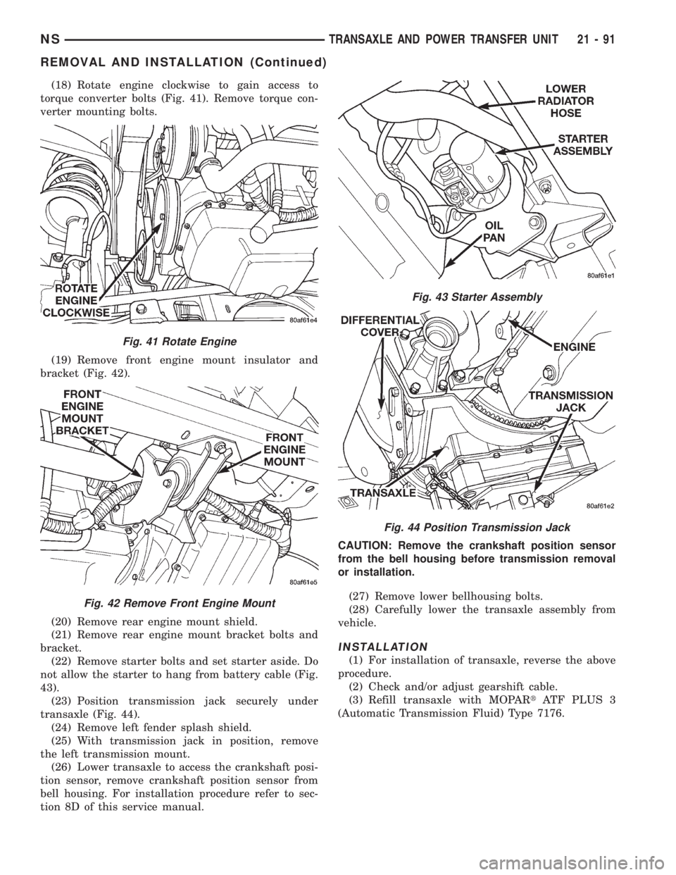
(18) Rotate engine clockwise to gain access to
torque converter bolts (Fig. 41). Remove torque con-
verter mounting bolts.
(19) Remove front engine mount insulator and
bracket (Fig. 42).
(20) Remove rear engine mount shield.
(21) Remove rear engine mount bracket bolts and
bracket.
(22) Remove starter bolts and set starter aside. Do
not allow the starter to hang from battery cable (Fig.
43).
(23) Position transmission jack securely under
transaxle (Fig. 44).
(24) Remove left fender splash shield.
(25) With transmission jack in position, remove
the left transmission mount.
(26) Lower transaxle to access the crankshaft posi-
tion sensor, remove crankshaft position sensor from
bell housing. For installation procedure refer to sec-
tion 8D of this service manual.CAUTION: Remove the crankshaft position sensor
from the bell housing before transmission removal
or installation.
(27) Remove lower bellhousing bolts.
(28) Carefully lower the transaxle assembly from
vehicle.
INSTALLATION
(1) For installation of transaxle, reverse the above
procedure.
(2) Check and/or adjust gearshift cable.
(3) Refill transaxle with MOPARtATF PLUS 3
(Automatic Transmission Fluid) Type 7176.
Fig. 41 Rotate Engine
Fig. 42 Remove Front Engine Mount
Fig. 43 Starter Assembly
Fig. 44 Position Transmission Jack
NSTRANSAXLE AND POWER TRANSFER UNIT 21 - 91
REMOVAL AND INSTALLATION (Continued)
Page 1660 of 1938
²Improper operation
HARD SHIFTING
Hard shifting may be caused by a misadjusted
crossover cable. If hard shifting is accompanied by
gear clash, synchronizer clutch and stop rings or gear
teeth may be worn or damaged.
Misassembled synchronizer components also cause
shifting problems. Incorrectly installed synchronizer
sleeves, struts, or springs can cause shift problems.
NOISY OPERATION
Transaxle noise is most often a result of worn or
damaged components. Chipped, broken gear or syn-
chronizer teeth, and brinnelled, spalled bearings all
cause noise.
Abnormal wear and damage to the internal compo-
nents is frequently the end result of insufficient
lubricant.
SLIPS OUT OF GEAR
Transaxle disengagement may be caused by mis-
aligned or damaged shift components, or worn teeth
on the drive gears or synchronizer components. Incor-
rect assembly also causes gear disengagement.
LOW LUBRICANT LEVEL
Insufficient transaxle lubricant is usually the
result of leaks, or inaccurate fluid level check or refill
method. Leakage is evident by the presence of oil
around the leak point. If leakage is not evident, the
condition is probably the result of an underfill.
If air±powered lubrication equipment is used to fill
a transaxle, be sure the equipment is properly cali-
brated. Equipment out of calibration can lead to an
underfill condition.
The transaxle fill plug is located on the lower left
side of the transaxle end cover. With the vehicle at a
level position, remove the fill plug and check the
level of the lubricant. The lubricant level should be
within 3.175mm (1/8 inch) from the bottom of the fill
hole. If the lubricant level is low, fill the transaxle to
the bottom of the fill hole with SAE 5W-30 engine oil,
meeting SG and/or SG-CD qualifications, as the fac-
tory fill lubricant. SAE GL5 10W-40 engine oil is a
suitable service fill alternative.
CLUTCH PROBLEMS
Worn, damaged, or misaligned clutch components
can cause difficult shifting, gear clash, and noise.
A worn or damaged clutch disc, pressure plate, or
release bearing can cause hard shifting and gear
clash.
SERVICE PROCEDURES
FLUID DRAIN AND FILL
TRANSAXLE FLUID DRAIN
(1) Hoist vehicle.
(2) Install a drain pan underneath the transaxle
drain plug.
(3) Remove the transaxle drain plug. The drain
plug is located on the bottom of the transaxle hous-
ing.
(4) Let fluid drain out till there is just an occa-
sional drip.
(5) Reinstall drain plug. Tighten drain plug to 28
N´m (250 in. lbs.)
TRANSAXLE FLUID FILL
NOTE: All A-598 transaxles are equipped with a fill
plug. The fill plug is located on the end cover side
of the transaxle.
(1) Remove transaxle fill plug
The fluid level should be within 3.175mm (1/8
inch) from the bottom of the transaxle fill hole (vehi-
cle must be level when checking).
(2) Fill transaxle to proper level with SAE 5W-30
engine oil, meeting SG and/or SG-CD qualifications.
G5 SAE 10W-40 engine oil is a suitable service fill
alternative. Dry fill lubricant capacity is approxi-
mately 1.9-2.2 liters (4.0-4.6 pints)..
(3) Wipe the outside of the transaxle if any lubri-
cant spills.
(4) Reinstall transaxle fill plug.
FLUID DRAIN AND FILLÐRHD VEHICLES
TRANSAXLE FLUID DRAIN
(1) Hoist vehicle.
(2) Install a drain pan underneath the transaxle
drain plug.
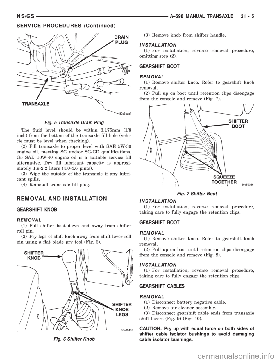
(3) Remove the transaxle drain plug. The drain
plug is located on the bottom of the transaxle hous-
ing (Fig. 5).
(4) Let fluid drain out till there is just an occa-
sional drip.
(5) Reinstall drain plug. Tighten drain plug to 28
N´m (250 in. lbs.)
TRANSAXLE FLUID FILL
NOTE: All A-558 transaxles are equipped with a fill
plug. The fill plug is located on the end cover side
of the transaxle.
(1) Remove transaxle fill plug
21 - 4 A±598 MANUAL TRANSAXLENS/GS
DIAGNOSIS AND TESTING (Continued)
Page 1661 of 1938
The fluid level should be within 3.175mm (1/8
inch) from the bottom of the transaxle fill hole (vehi-
cle must be level when checking).
(2) Fill transaxle to proper level with SAE 5W-30
engine oil, meeting SG and/or SG-CD qualifications.
G5 SAE 10W-40 engine oil is a suitable service fill
alternative. Dry fill lubricant capacity is approxi-
mately 1.9-2.2 liters (4.0-4.6 pints).
(3) Wipe the outside of the transaxle if any lubri-
cant spills.
(4) Reinstall transaxle fill plug.
REMOVAL AND INSTALLATION
GEARSHIFT KNOB
REMOVAL
(1) Pull shifter boot down and away from shifter
roll pin.
(2) Pry legs of shift knob away from shift lever roll
pin using a flat blade pry tool (Fig. 6).(3) Remove knob from shifter handle.
INSTALLATION
(1) For installation, reverse removal procedure,
omitting step (2).
GEARSHIFT BOOT
REMOVAL
(1) Remove shifter knob. Refer to gearshift knob
removal.
(2) Pull up on boot until retention clips disengage
from the console and remove (Fig. 7).
INSTALLATION
(1) For installation, reverse removal procedure,
taking care to fully engage the retention clips.
GEARSHIFT BOOT
REMOVAL
(1) Remove shifter knob. Refer to gearshift knob
removal.
(2) Pull up on boot until retention clips disengage
from the console and remove (Fig. 8).
INSTALLATION
(1) For installation, reverse removal procedure,
taking care to fully engage the retention clips.
GEARSHIFT CABLES
REMOVAL
(1) Disconnect battery negative cable.
(2) Remove air cleaner assembly.
(3) Disconnect gearshift cable ends from transaxle
shift levers (Fig. 9) (Fig. 10).
CAUTION: Pry up with equal force on both sides of
shifter cable isolator bushings to avoid damaging
cable isolator bushings.
Fig. 5 Transaxle Drain Plug
Fig. 6 Shifter Knob
Fig. 7 Shifter Boot
NS/GSA±598 MANUAL TRANSAXLE 21 - 5
SERVICE PROCEDURES (Continued)
Page 1663 of 1938
INSTALLATION
(1) To install, reverse removal procedure. After
cables have been replaced, cable adjustment should
be checked. Refer to cable adjustment procedure in
this section.
NOTE: High temperature tie straps must be used
when replacing cable(s). Locate the new tie strap at
the white band on the crossover cable and cinch
cables tightly together.
CAUTION: Only the crossover cable is adjustable.
The selector cable does not have any adjustment
capabilities.
GEARSHIFT CABLESÐRHD VEHICLES
REMOVAL
(1) Disconnect battery negative cable.
(2) Remove air cleaner assembly.(3) Disconnect gearshift cable ends from transaxle
shift levers (Fig. 16) (Fig. 17).
CAUTION: Pry up with equal force on both sides of
shifter cable isolator bushings to avoid damaging
cable isolator bushings.
(4) Remove cable to bracket retaining clips at tran-
saxle (Fig. 18).
CAUTION: It is recommended that new cable retain-
ing clips be used for reinstallation.
(5) Pull cables up out of engine mount bracket.
(6) Remove gearshift knob and boot. Refer to Knob
and Boot Removal in this section.
(7) Remove console screws (Fig. 19).
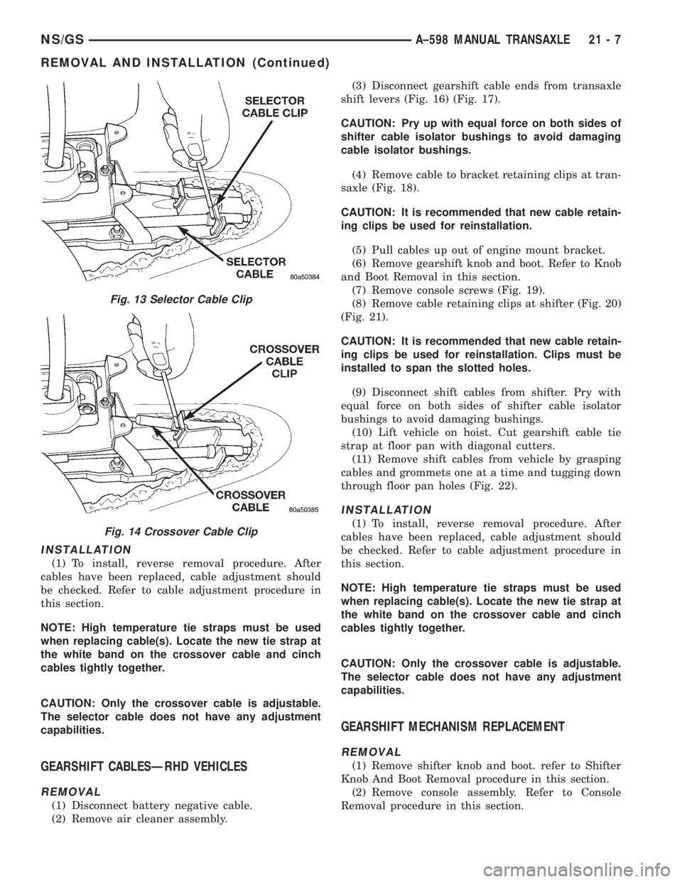
(8) Remove cable retaining clips at shifter (Fig. 20)
(Fig. 21).
CAUTION: It is recommended that new cable retain-
ing clips be used for reinstallation. Clips must be
installed to span the slotted holes.
(9) Disconnect shift cables from shifter. Pry with
equal force on both sides of shifter cable isolator
bushings to avoid damaging bushings.
(10) Lift vehicle on hoist. Cut gearshift cable tie
strap at floor pan with diagonal cutters.
(11) Remove shift cables from vehicle by grasping
cables and grommets one at a time and tugging down
through floor pan holes (Fig. 22).
INSTALLATION
(1) To install, reverse removal procedure. After
cables have been replaced, cable adjustment should
be checked. Refer to cable adjustment procedure in
this section.
NOTE: High temperature tie straps must be used
when replacing cable(s). Locate the new tie strap at
the white band on the crossover cable and cinch
cables tightly together.
CAUTION: Only the crossover cable is adjustable.
The selector cable does not have any adjustment
capabilities.
GEARSHIFT MECHANISM REPLACEMENT
REMOVAL
(1) Remove shifter knob and boot. refer to Shifter
Knob And Boot Removal procedure in this section.
(2) Remove console assembly. Refer to Console
Removal procedure in this section.
Fig. 13 Selector Cable Clip
Fig. 14 Crossover Cable Clip
NS/GSA±598 MANUAL TRANSAXLE 21 - 7
REMOVAL AND INSTALLATION (Continued)
Page 1671 of 1938
(4) Check the transaxle for leaks and recheck the
level of the transaxle lubricant.
INPUT SHAFT FRONT BEARING RETAINER
REMOVAL
(1) Remove the transaxle assembly from the vehi-
cle. For removal procedure, refer to Transaxle,
Removal and Installation.
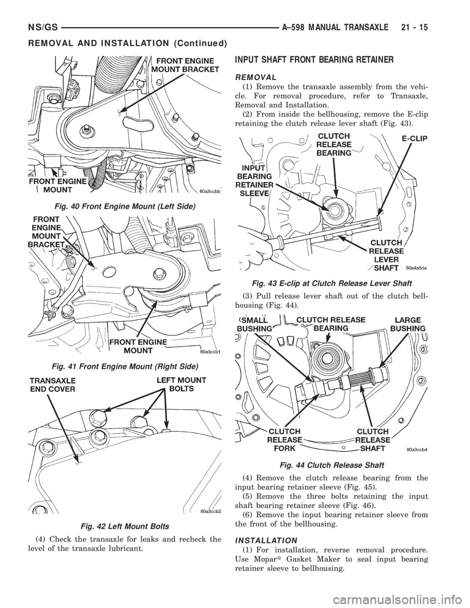
(2) From inside the bellhousing, remove the E-clip
retaining the clutch release lever shaft (Fig. 43).
(3) Pull release lever shaft out of the clutch bell-
housing (Fig. 44).
(4) Remove the clutch release bearing from the
input bearing retainer sleeve (Fig. 45).
(5) Remove the three bolts retaining the input
shaft bearing retainer sleeve (Fig. 46).
(6) Remove the input bearing retainer sleeve from
the front of the bellhousing.
INSTALLATION
(1) For installation, reverse removal procedure.
Use MopartGasket Maker to seal input bearing
retainer sleeve to bellhousing.
Fig. 40 Front Engine Mount (Left Side)
Fig. 41 Front Engine Mount (Right Side)
Fig. 42 Left Mount Bolts
Fig. 43 E-clip at Clutch Release Lever Shaft
Fig. 44 Clutch Release Shaft
NS/GSA±598 MANUAL TRANSAXLE 21 - 15
REMOVAL AND INSTALLATION (Continued)
Page 1676 of 1938
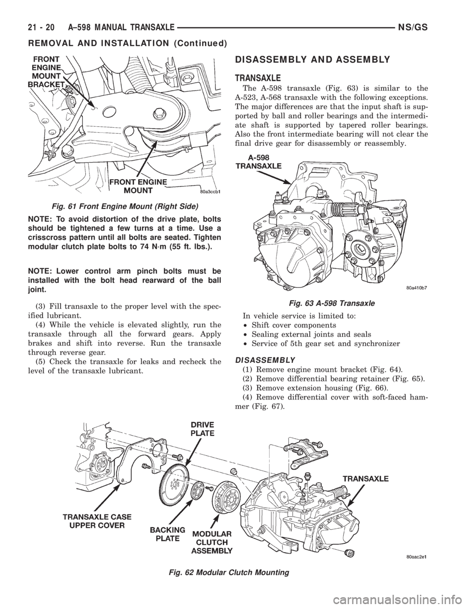
NOTE: To avoid distortion of the drive plate, bolts
should be tightened a few turns at a time. Use a
crisscross pattern until all bolts are seated. Tighten
modular clutch plate bolts to 74 N´m (55 ft. lbs.).
NOTE: Lower control arm pinch bolts must be
installed with the bolt head rearward of the ball
joint.
(3) Fill transaxle to the proper level with the spec-
ified lubricant.
(4) While the vehicle is elevated slightly, run the
transaxle through all the forward gears. Apply
brakes and shift into reverse. Run the transaxle
through reverse gear.
(5) Check the transaxle for leaks and recheck the
level of the transaxle lubricant.
DISASSEMBLY AND ASSEMBLY
TRANSAXLE
The A-598 transaxle (Fig. 63) is similar to the
A-523, A-568 transaxle with the following exceptions.
The major differences are that the input shaft is sup-
ported by ball and roller bearings and the intermedi-
ate shaft is supported by tapered roller bearings.
Also the front intermediate bearing will not clear the
final drive gear for disassembly or reassembly.
In vehicle service is limited to:
²Shift cover components
²Sealing external joints and seals
²Service of 5th gear set and synchronizer
DISASSEMBLY
(1) Remove engine mount bracket (Fig. 64).
(2) Remove differential bearing retainer (Fig. 65).
(3) Remove extension housing (Fig. 66).
(4) Remove differential cover with soft-faced ham-
mer (Fig. 67).
Fig. 62 Modular Clutch Mounting
Fig. 61 Front Engine Mount (Right Side)
Fig. 63 A-598 Transaxle
21 - 20 A±598 MANUAL TRANSAXLENS/GS
REMOVAL AND INSTALLATION (Continued)
Page 1716 of 1938
SPECIAL TOOLS
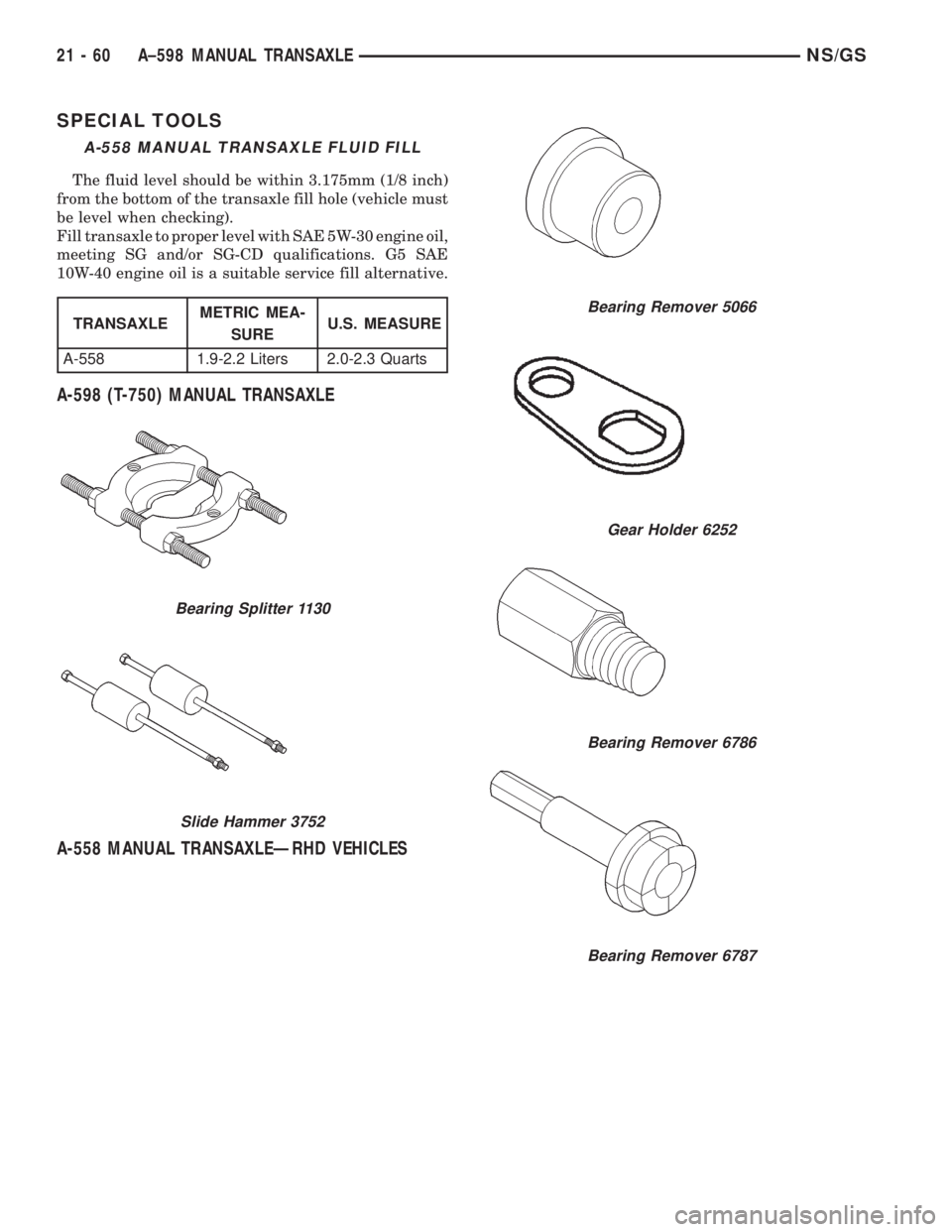
A-598 (T-750) MANUAL TRANSAXLE
A-558 MANUAL TRANSAXLEÐRHD VEHICLES
A-558 MANUAL TRANSAXLE FLUID FILL
The fluid level should be within 3.175mm (1/8 inch)
from the bottom of the transaxle fill hole (vehicle must
be level when checking).
Fill transaxle to proper level with SAE 5W-30 engine oil,
meeting SG and/or SG-CD qualifications. G5 SAE
10W-40 engine oil is a suitable service fill alternative.
TRANSAXLEMETRIC MEA-
SUREU.S. MEASURE
A-558 1.9-2.2 Liters 2.0-2.3 Quarts
Bearing Splitter 1130
Slide Hammer 3752
Bearing Remover 5066
Gear Holder 6252
Bearing Remover 6786
Bearing Remover 6787
21 - 60 A±598 MANUAL TRANSAXLENS/GS