1996 CHRYSLER VOYAGER battery
[x] Cancel search: batteryPage 1055 of 1938
CAUTION: Be sure that the tapped holes maintain
the original centerline.
Heli-Coil tools and inserts are readily available
from automotive parts jobbers.
HYDROSTATIC LOCKED ENGINE
When an engine is suspected to be hydrostatically
locked, regardless of what caused the problem, these
steps should be used.
CAUTION: Do Not Use Starter Motor To Rotate
Engine, severe damage may occur.
(1) Inspect air cleaner, induction system and
intake manifold to insure system is dry and clear of
foreign material.
(2) Remove negative battery cable.
(3) Place a shop towel around the spark plugs
when removing them from the engine. This will catch
any fluid that may possibly be in the cylinder under
pressure.
(4) With all spark plugs removed, rotate engine
crankshaft using a breaker bar and socket.
(5) Identify the fluid in the cylinder(s) (i.e., cool-
ant, fuel, oil or other).
(6) Make sure all fluid has been removed from the
cylinders. Inspect engine for damage (i.e., Connecting
Rods, Pistons, Valves etc.)
(7) Repair engine or components as necessary to
prevent this problem from occurring again.
CAUTION: Squirt approximately 1 teaspoon of oil
into cylinders, rotate engine to lubricate the cylin-
der walls to prevent damage on restart.
(8) Install new spark plugs.
(9) Drain engine oil and remove oil filter.
(10) Fill engine with specified amount of approved
oil and install new oil filter.
(11) Connect negative battery cable.
(12) Start engine and check for any leaks.
ENGINE OIL
Checking Oil Level
To assure proper engine lubrication, the engine oil
must be maintained at the correct level. Check the
oil level at regular intervals, such as every fuel stop.
The best time to check the oil level is about 5 min-
utes after a fully warmed-up engine is shut off, or
before starting the vehicle after it has sat overnight.
Checking the oil while the vehicle is on level
ground, will improve the accuracy of the oil level
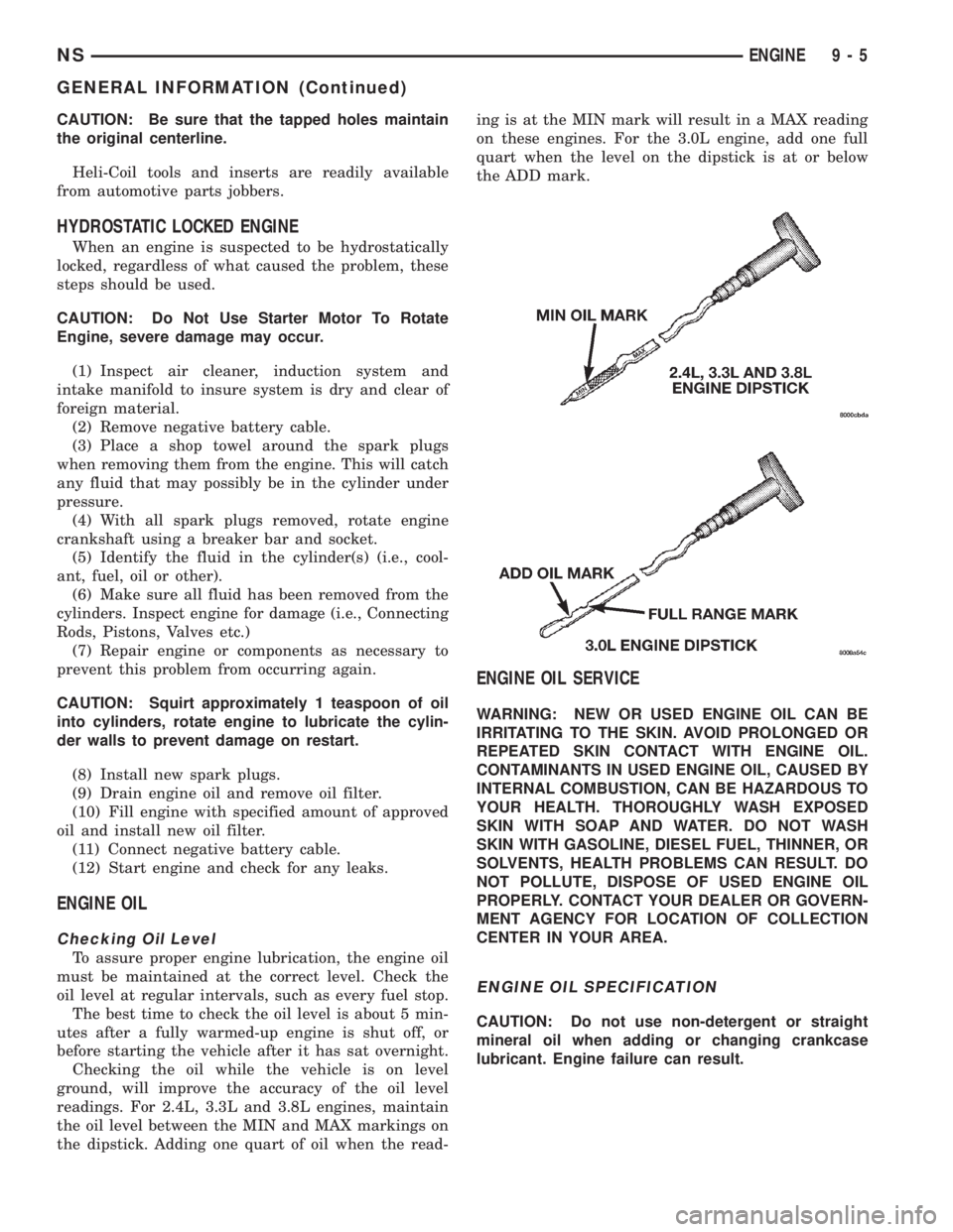
readings. For 2.4L, 3.3L and 3.8L engines, maintain
the oil level between the MIN and MAX markings on
the dipstick. Adding one quart of oil when the read-ing is at the MIN mark will result in a MAX reading
on these engines. For the 3.0L engine, add one full
quart when the level on the dipstick is at or below
the ADD mark.
ENGINE OIL SERVICE
WARNING: NEW OR USED ENGINE OIL CAN BE
IRRITATING TO THE SKIN. AVOID PROLONGED OR
REPEATED SKIN CONTACT WITH ENGINE OIL.
CONTAMINANTS IN USED ENGINE OIL, CAUSED BY
INTERNAL COMBUSTION, CAN BE HAZARDOUS TO
YOUR HEALTH. THOROUGHLY WASH EXPOSED
SKIN WITH SOAP AND WATER. DO NOT WASH
SKIN WITH GASOLINE, DIESEL FUEL, THINNER, OR
SOLVENTS, HEALTH PROBLEMS CAN RESULT. DO
NOT POLLUTE, DISPOSE OF USED ENGINE OIL
PROPERLY. CONTACT YOUR DEALER OR GOVERN-
MENT AGENCY FOR LOCATION OF COLLECTION
CENTER IN YOUR AREA.
ENGINE OIL SPECIFICATION
CAUTION: Do not use non-detergent or straight
mineral oil when adding or changing crankcase
lubricant. Engine failure can result.
NSENGINE 9 - 5
GENERAL INFORMATION (Continued)
Page 1057 of 1938
ENGINE DIAGNOSIS
INDEX
page page
DIAGNOSIS AND TESTING
CYLINDER COMBUSTION
PRESSURE LEAKAGE TEST.............. 8
CYLINDER COMPRESSION PRESSURE TEST . . 7
ENGINE DIAGNOSISÐMECHANICAL......... 12
ENGINE DIAGNOSISÐPERFORMANCE...... 10GENERAL INFORMATION.................. 7
INSPECTION
(ENGINE OIL LEAKS IN GENERAL)......... 8
INTAKE MANIFOLD LEAKAGE DIAGNOSIS..... 7
LASH ADJUSTER (TAPPET)
NOISE DIAGNOSIS...................... 8
DIAGNOSIS AND TESTING
GENERAL INFORMATION
Engine diagnosis is helpful in determining the
causes of malfunctions.
These malfunctions may be classified as either
mechanical (e.g., a strange noise), or performance
(e.g., engine idles rough and stalls).
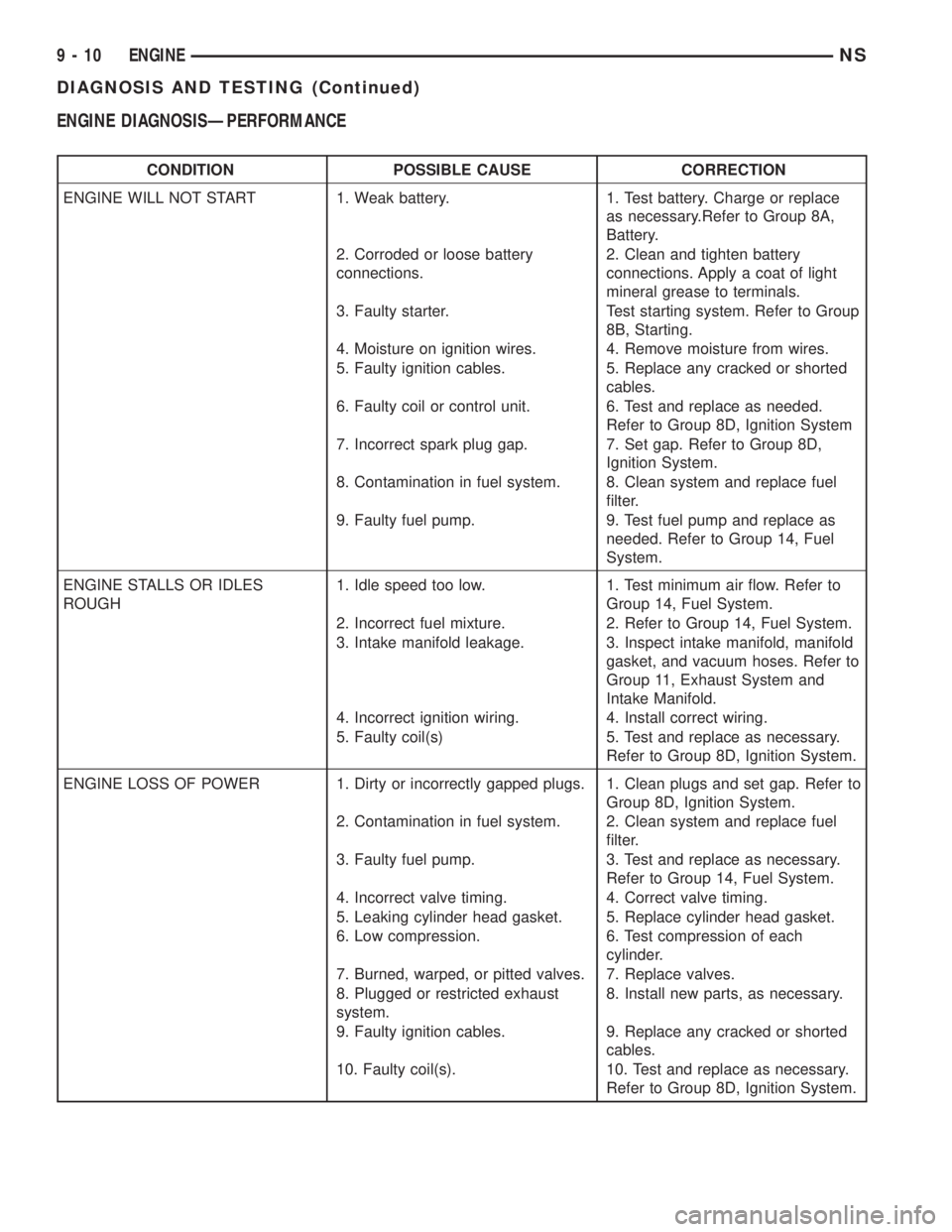
Refer to the Service DiagnosisÐMechanical Chart
and the Service DiagnosisÐPerformance Chart, for
possible causes and corrections of malfunctions. Refer
to Group 14, Fuel System, for the fuel system diag-
nosis.
Additional tests and diagnostic procedures may be
necessary for specific engine malfunctions that can-
not be isolated with the Service Diagnosis charts.
Information concerning additional tests and diagno-
sis is provided within the following:
²Cylinder Compression Pressure Test
²Cylinder Combustion Pressure Leakage Test
²Engine Cylinder Head Gasket Failure Diagnosis
²Intake Manifold Leakage Diagnosis
INTAKE MANIFOLD LEAKAGE DIAGNOSIS
An intake manifold air leak is characterized by
lower than normal manifold vacuum. Also, one or
more cylinders may not be functioning.
WARNING: USE EXTREME CAUTION WHEN THE
ENGINE IS OPERATING. DO NOT STAND IN A
DIRECT LINE WITH THE FAN. DO NOT PUT YOUR
HANDS NEAR THE PULLEYS, BELTS OR THE FAN.
DO NOT WEAR LOOSE CLOTHING.
(1) Start the engine.
(2) Spray a small stream of water (Spray Bottle) at
the suspected leak area.
(3) If a change in RPM'S, the area of the suspected
leak has been found.
(4) Repair as required.
CYLINDER COMPRESSION PRESSURE TEST
The results of a cylinder compression pressure test
can be utilized to diagnose several engine malfunc-
tions.
Ensure the battery is completely charged and the
engine starter motor is in good operating condition.
Otherwise the indicated compression pressures may
not be valid for diagnosis purposes.
(1) Check engine oil level and add oil if necessary.
(2) Drive the vehicle until engine reaches normal
operating temperature. Select a route free from traf-
fic and other forms of congestion, observe all traffic
laws, and accelerate through the gears several times
briskly.
(3) Remove all spark plugs from engine. As spark
plugs are being removed, check electrodes for abnor-
mal firing indicators fouled, hot, oily, etc. Record cyl-
inder number of spark plug for future reference.
(4) Disconnect coil wire from distributor and
secure to good ground to prevent a spark from start-
ing a fire (Conventional Ignition System). For Direct
Ignition System DIS disconnect the coil connector.
(5) Be sure throttle blade is fully open during the
compression check.
(6) Insert compression gage adaptor into the #1
spark plug hole in cylinder head. Crank engine until
maximum pressure is reached on gage. Record this
pressure as #1 cylinder pressure.
(7) Repeat the previous step for all remaining cyl-
inders.
(8) Compression should not be less than (689kPa)
100 psi and not vary more than 25 percent from cyl-
inder to cylinder.
(9) If one or more cylinders have abnormally low
compression pressures, repeat the compression test.
(10) If the same cylinder or cylinders repeat an
abnormally low reading on the second compression
test, it could indicate the existence of a problem in
the cylinder in question.The recommended com-
pression pressures are to be used only as a
guide to diagnosing engine problems. An engine
should not be disassembled to determine the
NSENGINE 9 - 7
Page 1059 of 1938
(2) Add an oil soluble dye (use as recommended by
manufacturer). Start the engine and let idle for
approximately 15 minutes. Check the oil dipstick to
make sure the dye is thoroughly mixed as indicated
with a bright yellow color under a black light.
(3) Using a black light, inspect the entire engine
for fluorescent dye, particularly at the suspected area
of oil leak. If the oil leak is found and identified,
repair per service manual instructions.
(4) If dye is not observed, drive the vehicle at var-
ious speeds for approximately 24km (15 miles), and
repeat inspection.
(5)If the oil leak source is not positively
identified at this time, proceed with the air leak
detection test method as follows:
(6) Disconnect the fresh air hose (makeup air) at
the cylinder head cover and plug or cap the nipple on
the cover.
(7) Remove the PCV valve hose from the cylinder
head cover. Cap or plug the PCV valve nipple on the
cover.
(8) Attach an air hose with pressure gauge and
regulator to the dipstick tube.
CAUTION: Do not subject the engine assembly to
more than 20.6 kpa (3 PSI) of test pressure.
(9) Gradually apply air pressure from 1 psi to 2.5
psi maximum while applying soapy water at the sus-
pected source. Adjust the regulator to the suitable
test pressure that provide the best bubbles which
will pinpoint the leak source. If the oil leak is
detected and identified, repair per service manual
procedures.
(10) If the leakage occurs at the rear oil seal area,
refer to the section, Inspection for Rear Seal Area
Leak.
(11) If no leaks are detected, turn off the air sup-
ply and remove the air hose and all plugs and caps.
Install the PCV valve and breather cap hose. Proceed
to next step.
(12) Clean the oil off the suspect oil leak area
using a suitable solvent. Drive the vehicle at various
speeds approximately 24 km (15 miles). Inspect the
engine for signs of an oil leak by using a black light.INSPECTION FOR REAR SEAL AREA LEAKS
Since it is sometimes difficult to determine the
source of an oil leak in the rear seal area of the
engine, a more involved inspection is necessary. The
following steps should be followed to help pinpoint
the source of the leak.
If the leakage occurs at the crankshaft rear oil seal
area:
(1) Disconnect the battery.
(2) Raise the vehicle.
(3) Remove torque converter or clutch housing
cover and inspect rear of block for evidence of oil.
Use a black light to check for the oil leak. If a leak is
present in this area remove transmission for further
inspection.
(a) Circular spray pattern generally indicates
seal leakage or crankshaft damage.
(b) Where leakage tends to run straight down,
possible causes are a porous block, oil galley cup
plug, bedplate to cylinder block mating surfaces
and seal bore. See proper repair procedures for
these items.
(4) If no leaks are detected, pressurized the crank-
case as outlined in the, Inspection (Engine oil Leaks
in general)
CAUTION: Do not exceed 20.6 kPa (3 psi).
(5) If the leak is not detected, very slowly turn the
crankshaft and watch for leakage. If a leak is
detected between the crankshaft and seal while
slowly turning the crankshaft, it is possible the
crankshaft seal surface is damaged. The seal area on
the crankshaft could have minor nicks or scratches
that can be polished out with emery cloth.
CAUTION: Use extreme caution when crankshaft
polishing is necessary to remove minor nicks and
scratches. The crankshaft seal flange is especially
machined to complement the function of the rear oil
seal.
(6) For bubbles that remain steady with shaft
rotation, no further inspection can be done until dis-
assembled.
(7) After the oil leak root cause and appropriate
corrective action have been identified. Refer to Rear
Crankshaft Seals, for proper replacement procedures.
NSENGINE 9 - 9
DIAGNOSIS AND TESTING (Continued)
Page 1060 of 1938
ENGINE DIAGNOSISÐPERFORMANCE
CONDITION POSSIBLE CAUSE CORRECTION
ENGINE WILL NOT START 1. Weak battery. 1. Test battery. Charge or replace
as necessary.Refer to Group 8A,
Battery.
2. Corroded or loose battery
connections.2. Clean and tighten battery
connections. Apply a coat of light
mineral grease to terminals.
3. Faulty starter. Test starting system. Refer to Group
8B, Starting.
4. Moisture on ignition wires. 4. Remove moisture from wires.
5. Faulty ignition cables. 5. Replace any cracked or shorted
cables.
6. Faulty coil or control unit. 6. Test and replace as needed.
Refer to Group 8D, Ignition System
7. Incorrect spark plug gap. 7. Set gap. Refer to Group 8D,
Ignition System.
8. Contamination in fuel system. 8. Clean system and replace fuel
filter.
9. Faulty fuel pump. 9. Test fuel pump and replace as
needed. Refer to Group 14, Fuel
System.
ENGINE STALLS OR IDLES
ROUGH1. Idle speed too low. 1. Test minimum air flow. Refer to
Group 14, Fuel System.
2. Incorrect fuel mixture. 2. Refer to Group 14, Fuel System.
3. Intake manifold leakage. 3. Inspect intake manifold, manifold
gasket, and vacuum hoses. Refer to
Group 11, Exhaust System and
Intake Manifold.
4. Incorrect ignition wiring. 4. Install correct wiring.
5. Faulty coil(s) 5. Test and replace as necessary.
Refer to Group 8D, Ignition System.
ENGINE LOSS OF POWER 1. Dirty or incorrectly gapped plugs. 1. Clean plugs and set gap. Refer to
Group 8D, Ignition System.
2. Contamination in fuel system. 2. Clean system and replace fuel
filter.
3. Faulty fuel pump. 3. Test and replace as necessary.
Refer to Group 14, Fuel System.
4. Incorrect valve timing. 4. Correct valve timing.
5. Leaking cylinder head gasket. 5. Replace cylinder head gasket.
6. Low compression. 6. Test compression of each
cylinder.
7. Burned, warped, or pitted valves. 7. Replace valves.
8. Plugged or restricted exhaust
system.8. Install new parts, as necessary.
9. Faulty ignition cables. 9. Replace any cracked or shorted
cables.
10. Faulty coil(s). 10. Test and replace as necessary.
Refer to Group 8D, Ignition System.
9 - 10 ENGINENS
DIAGNOSIS AND TESTING (Continued)
Page 1076 of 1938
ENGINE ASSEMBLY
REMOVAL
(1) Perform fuel pressure release procedure. Refer
to Group 14, Fuel System for procedure. Remove fuel
line to fuel rail.
(2) Disconnect battery.
(3) Remove Air cleaner and hoses.
(4) Drain cooling system. Refer to Group 7, Cooling
System for procedure.
(5) Remove upper radiator hose and remove radia-
tor fans. Refer to Group 7, Cooling System for proce-
dure.
(6) Remove lower radiator hose.
(7) Disconnect automatic transmission cooler lines
and plug, if equipped.
(8) Disconnect transmission shift linkage.
(9) Disconnect throttle body linkage.
(10) Disconnect engine wiring harness.
(11) Disconnect heater hoses.
(12) Discharge Air Conditioning System. Refer to
Group 24, Air Conditioning for procedure.
(13) Hoist vehicle and remove right inner splash
shield. Remove wheels and tires.
(14) Loosen power steering belt for pump removal.
Refer to Group 7, Cooling System for procedure.
(15) Remove axle shafts. Refer to Group 2, Suspen-
sion and Driveshafts for procedure.
(16) Disconnect exhaust pipe from manifold.
(17) Remove front and rear engine mount brackets
from the body.
(18) Remove bending braces and front engine
mount bracket. Remove transmission inspection
cover.
(19) Mark flexplate to torque converter and
remove torque converter bolts.
(20) Install front engine mount bracket.
(21) Lower vehicle.
(22) Remove power steering pump. Set pump
aside.
(23) Remove A/C lines at compressor and cap.
(24) Remove ground straps to body.
(25) Raise vehicle enough to allow engine dolly
Special Tool 6135, cradle Special Tool 6710 with
Posts Special Tool 6848 and Adaptor Special Tool
8130 to be installed under vehicle (Fig. 27).
(26) Loosen cradle posts to allow movement for
proper positioning. Locate two rear posts (right side
of engine) into the holes on the engine bedplate.
Locate the two front posts (left side of engine) on the
front engine bracket and A/C compressor bracket
(Fig. 27). Lower vehicle and position cradle mounts
until the engine is resting on mounts. Tighten
mounts to cradle frame. This will keep mounts from
moving when removing or installing engine and
transmission.(27) Lower vehicle so the weight ofONLY THE
ENGINE AND TRANSMISSIONare on the cradle.
(28) Remove engine and transmission mount bolts.
(29) Raise vehicle slowly. It may be necessary to
move the engine/transmission assembly on the cradle
to allow for removal around the body.
INSTALLATION
(1) Position engine and transmission assembly
under vehicle and slowly lower the vehicle over the
engine and transmission.
(2) Align engine and transmission mounts to
attaching points. Install mounting bolts at the right
engine and left transmission mounts. Refer to proce-
dures outlined in this section.
(3) Slowly raise vehicle enough to remove the
engine dolly and cradle Special Tools 6135 and 6710.
(4) Install axle shafts. Refer to Group 2, Suspen-
sion and Driveshafts for procedure.
(5) Install transmission and engine braces and
splash shields.
(6) Connect exhaust system to manifold. Refer to
Group 11, Exhaust System and Intake Manifold for
procedure and torque specifications.
(7) Install power steering pump. Refer to Cooling
System Group 7, Accessory Drive Section for belt ten-
sion adjustment.
(8) Install A/C compressor hoses. Refer to Group
24, Heater and Air Conditioning for procedure.
(9) Install accessory drive belts. Refer to Group 7,
Cooling System Accessory Drive Section for belt ten-
sion adjustment.
(10) Install front and rear engine mounts. Refer to
this section for procedure.
(11) Install inner splash shield. Install wheels and
tires.
(12) Connect automatic transmission cooler lines,
and shift linkage. Refer to Group 21, Transmission
for procedures.
(13) Connect fuel line and heater hoses.
(14) Install ground straps. Connect engine and
throttle body connections and harnesses. Refer to
Group 8, Electrical for procedure.
(15) Connect throttle body linkage. Refer to Group
14, Fuel System for procedure.
(16) Install radiator fans. Install radiator hoses.
Fill cooling system. Refer to Group 7, Cooling System
for filling procedure.
(17) Connect battery.
(18) Install air cleaner and hoses.
(19) Install oil filter. Fill engine crankcase with
proper oil to correct level.
(20) Start engine and run until operating temper-
ature is reached.
(21) Adjust transmission linkage, if necessary.
9 - 26 2.4L ENGINENS
REMOVAL AND INSTALLATION (Continued)
Page 1084 of 1938
CYLINDER HEAD
REMOVAL
(1) Perform fuel system pressure release proce-
durebefore attempting any repairs.Refer to
Group 14, Fuel System for procedure.
(2) Disconnect negative battery cable. Drain cool-
ing system. Refer to Group 7, Cooling System for pro-
cedure.
(3) Remove air cleaner and disconnect all vacuum
lines, electrical wiring and fuel lines from throttle
body.
(4) Remove throttle linkage. Refer to Group 14,
Fuel System for procedures
(5) Remove accessory drive belts. Refer to Group
7, Cooling System for procedure.
(6) Remove power brake vacuum hose from intake
manifold.
(7) Raise vehicle and remove exhaust pipe from
manifold.(8) Remove power steering pump assembly and
set aside.
(9) Disconnect coil pack wiring connector and
remove coil pack and plug wires from engine.
(10) Remove cam sensor and fuel injectors wiring
connectors.
(11) Remove timing belt and camshaft sprocket.
Refer to procedure outlined in this section.
(12) Remove timing belt idler pulley and rear tim-
ing belt cover.
(13) Remove cylinder head cover using procedure
outlined in this section.
(14) Remove camshafts and cam followers. Refer to
procedures outlined in this section for procedures.
(15) Remove cylinder head bolts and remove cyl-
inder head from engine block.
(16) Inspect and clean cylinder head. Refer to
Cleaning and Inspection outlined in this section for
procedures.
INSTALLATION
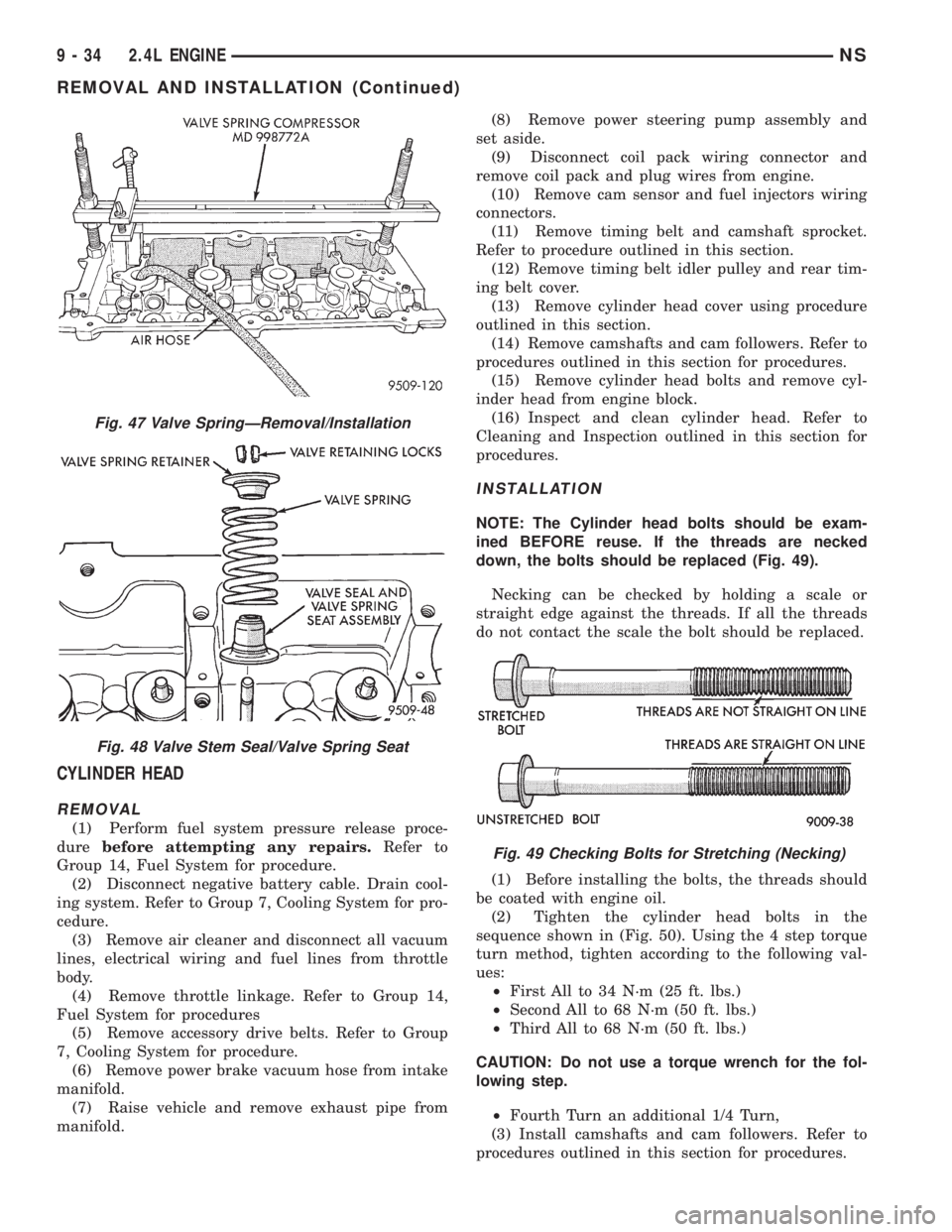
NOTE: The Cylinder head bolts should be exam-
ined BEFORE reuse. If the threads are necked
down, the bolts should be replaced (Fig. 49).
Necking can be checked by holding a scale or
straight edge against the threads. If all the threads
do not contact the scale the bolt should be replaced.
(1) Before installing the bolts, the threads should
be coated with engine oil.
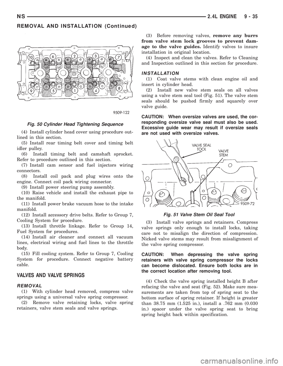
(2) Tighten the cylinder head bolts in the
sequence shown in (Fig. 50). Using the 4 step torque
turn method, tighten according to the following val-
ues:
²First All to 34 N´m (25 ft. lbs.)
²Second All to 68 N´m (50 ft. lbs.)
²Third All to 68 N´m (50 ft. lbs.)
CAUTION: Do not use a torque wrench for the fol-
lowing step.
²Fourth Turn an additional 1/4 Turn,
(3) Install camshafts and cam followers. Refer to
procedures outlined in this section for procedures.
Fig. 47 Valve SpringÐRemoval/Installation
Fig. 48 Valve Stem Seal/Valve Spring Seat
Fig. 49 Checking Bolts for Stretching (Necking)
9 - 34 2.4L ENGINENS
REMOVAL AND INSTALLATION (Continued)
Page 1085 of 1938
(4) Install cylinder head cover using procedure out-
lined in this section.
(5) Install rear timing belt cover and timing belt
idler pulley.
(6) Install timing belt and camshaft sprocket.
Refer to procedure outlined in this section.
(7) Install cam sensor and fuel injectors wiring
connectors.
(8) Install coil pack and plug wires onto the
engine. Connect coil pack wiring connector.
(9) Install power steering pump assembly.
(10) Raise vehicle and install the exhaust pipe to
the manifold.
(11) Install power brake vacuum hose to the intake
manifold.
(12) Install accessory drive belts. Refer to Group 7,
Cooling System for procedure.
(13) Install throttle linkage. Refer to Group 14,
Fuel System for procedures.
(14) Install air cleaner and connect all vacuum
lines, electrical wiring and fuel lines to the throttle
body.
(15) Fill cooling system. Refer to Group 7, Cooling
System for procedure. Connect negative battery
cable.
VALVES AND VALVE SPRINGS
REMOVAL
(1) With cylinder head removed, compress valve
springs using a universal valve spring compressor.
(2) Remove valve retaining locks, valve spring
retainers, valve stem seals and valve springs.(3) Before removing valves,remove any burrs
from valve stem lock grooves to prevent dam-
age to the valve guides.Identify valves to insure
installation in original location.
(4) Inspect and clean the valves. Refer to Cleaning
and Inspection outlined in this section for procedure.
INSTALLATION
(1) Coat valve stems with clean engine oil and
insert in cylinder head.
(2) Install new valve stem seals on all valves
using a valve stem seal tool (Fig. 51). The valve stem
seals should be pushed firmly and squarely over
valve guide.
CAUTION: When oversize valves are used, the cor-
responding oversize valve seal must also be used.
Excessive guide wear may result if oversize seals
are not used with oversize valves.
(3) Install valve springs and retainers. Compress
valve springs only enough to install locks, taking
care not to misalign the direction of compression.
Nicked valve stems may result from misalignment of
the valve spring compressor.
CAUTION: When depressing the valve spring
retainers with valve spring compressor the locks
can become dislocated. Ensure both locks are in
the correct location after removing tool.
(4) Check the valve spring installed height B after
refacing the valve and seat (Fig. 52). Make sure mea-
surements are taken from top of spring seat to the
bottom surface of spring retainer. If height is greater
than 38.75 mm (1.525 in.), install a .762 mm (0.030
in.) spacer under the valve spring seat to bring
spring height back within specification.
Fig. 50 Cylinder Head Tightening Sequence
Fig. 51 Valve Stem Oil Seal Tool
NS2.4L ENGINE 9 - 35
REMOVAL AND INSTALLATION (Continued)
Page 1097 of 1938
(7) Install main bearing bedplate to engine block
bolts 11, 17 and 20 finger tight. Tighten these bolts
down together until the bedplate contacts the cylin-
der block.
(8) To ensure correct thrust bearing alignment per-
form the following steps:
²Step 1: Rotate crankshaft until number 4 pis-
ton is at TDC.
²Step 2: Move crankshaft rearward to limits of
travel.
²Step 3: Then, move crankshaft forward to lim-
its of travel.
²Step 4: Wedge an appropraite tool between the
rear of the cylinder block(NOT BED PLATE)and
the rear crankshaft counterweight. This will hold the
crankshaft in it's furthest forward position.
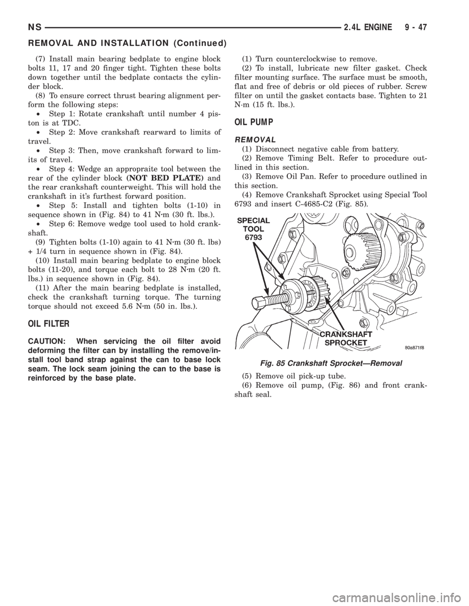
²Step 5: Install and tighten bolts (1-10) in
sequence shown in (Fig. 84) to 41 Nzm (30 ft. lbs.).
²Step 6: Remove wedge tool used to hold crank-
shaft.
(9) Tighten bolts (1-10) again to 41 Nzm (30 ft. lbs)
+ 1/4 turn in sequence shown in (Fig. 84).
(10) Install main bearing bedplate to engine block
bolts (11-20), and torque each bolt to 28 Nzm (20 ft.
lbs.) in sequence shown in (Fig. 84).
(11) After the main bearing bedplate is installed,
check the crankshaft turning torque. The turning
torque should not exceed 5.6 Nzm (50 in. lbs.).
OIL FILTER
CAUTION: When servicing the oil filter avoid
deforming the filter can by installing the remove/in-
stall tool band strap against the can to base lock
seam. The lock seam joining the can to the base is
reinforced by the base plate.(1) Turn counterclockwise to remove.
(2) To install, lubricate new filter gasket. Check
filter mounting surface. The surface must be smooth,
flat and free of debris or old pieces of rubber. Screw
filter on until the gasket contacts base. Tighten to 21
N´m (15 ft. lbs.).
OIL PUMP
REMOVAL
(1) Disconnect negative cable from battery.
(2) Remove Timing Belt. Refer to procedure out-
lined in this section.
(3) Remove Oil Pan. Refer to procedure outlined in
this section.
(4) Remove Crankshaft Sprocket using Special Tool
6793 and insert C-4685-C2 (Fig. 85).
(5) Remove oil pick-up tube.
(6) Remove oil pump, (Fig. 86) and front crank-
shaft seal.
Fig. 85 Crankshaft SprocketÐRemoval
NS2.4L ENGINE 9 - 47
REMOVAL AND INSTALLATION (Continued)