1996 CHRYSLER VOYAGER check engine
[x] Cancel search: check enginePage 1254 of 1938

VALVES AND VALVE SPRINGS
VALVE CLEANING
Clean all carbon deposits from the combustion
chambers, valve ports, valve stems, valve stem
guides and heads.
Clean all grime and gasket material from the
engine cylinder head machined gasket surfaces.
INSPECTION
Inspect for cracks in the combustion chambers and
valve ports.
Inspect for cracks on the exhaust seat.
Inspect for cracks in the gasket surface at each
coolant passage.
Inspect valves for burned, cracked or warped
heads.
Inspect for scuffed or bent valve stems.
Replace valves displaying any damage.
Check valve spring height. (Fig. 72).
HYDRAULIC TAPPETS
(1) Clean all tappet parts in a solvent that will
remove all varnish and carbon.
(2) Replace tappets that are unfit for further ser-
vice with new assemblies.
(3) If plunger shows signs of scoring or wear,
install a new tappet assembly. If valve is pitted, or
valve seat on end of plunger is prevented from seat-
ing, install a new tappet assembly.
OIL PUMP
CLEANING
Wash all parts in a suitable solvent and inspect
carefully for damage or wear (Fig. 74).
INSPECTION
(1) Before installing oil pump check pump bore
depth in block (A) and pump body height (B) (Fig.
73). Difference between A and B should be
0.020-0.082 mm.
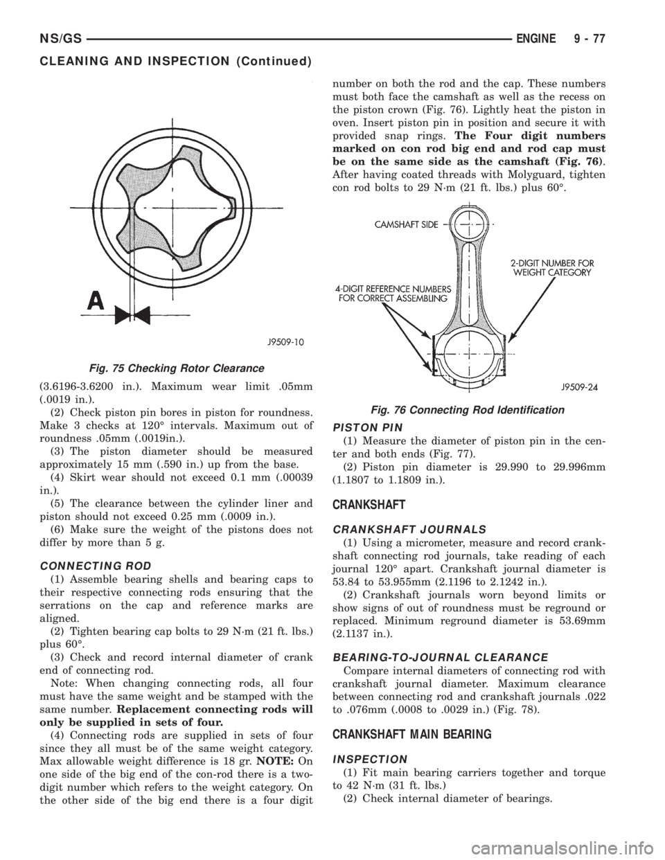
(2) Check clearance between rotors (Fig. 75).
PISTON AND CONNECTING ROD
PISTONS
(1) Piston Diameter: Size Group A: 91.93-91.94mm
(3.6191-3.6196 in.) Size Group B: 91.94-91.95mm
Fig. 72 Valve Spring Chart
Fig. 73 Oil Pump Bore Depth
Fig. 74 Oil Pump Inner and Outer Rotors
9 - 76 ENGINENS/GS
CLEANING AND INSPECTION (Continued)
Page 1255 of 1938
(3.6196-3.6200 in.). Maximum wear limit .05mm
(.0019 in.).
(2) Check piston pin bores in piston for roundness.
Make 3 checks at 120É intervals. Maximum out of
roundness .05mm (.0019in.).
(3) The piston diameter should be measured
approximately 15 mm (.590 in.) up from the base.
(4) Skirt wear should not exceed 0.1 mm (.00039
in.).
(5) The clearance between the cylinder liner and
piston should not exceed 0.25 mm (.0009 in.).
(6) Make sure the weight of the pistons does not
differ by more than 5 g.
CONNECTING ROD
(1) Assemble bearing shells and bearing caps to
their respective connecting rods ensuring that the
serrations on the cap and reference marks are
aligned.
(2) Tighten bearing cap bolts to 29 N´m (21 ft. lbs.)
plus 60É.
(3) Check and record internal diameter of crank
end of connecting rod.
Note: When changing connecting rods, all four
must have the same weight and be stamped with the
same number.Replacement connecting rods will
only be supplied in sets of four.
(4) Connecting rods are supplied in sets of four
since they all must be of the same weight category.
Max allowable weight difference is 18 gr.NOTE:On
one side of the big end of the con-rod there is a two-
digit number which refers to the weight category. On
the other side of the big end there is a four digitnumber on both the rod and the cap. These numbers
must both face the camshaft as well as the recess on
the piston crown (Fig. 76). Lightly heat the piston in
oven. Insert piston pin in position and secure it with
provided snap rings.The Four digit numbers
marked on con rod big end and rod cap must
be on the same side as the camshaft (Fig. 76).
After having coated threads with Molyguard, tighten
con rod bolts to 29 N´m (21 ft. lbs.) plus 60É.
PISTON PIN
(1) Measure the diameter of piston pin in the cen-
ter and both ends (Fig. 77).
(2) Piston pin diameter is 29.990 to 29.996mm
(1.1807 to 1.1809 in.).
CRANKSHAFT
CRANKSHAFT JOURNALS
(1) Using a micrometer, measure and record crank-
shaft connecting rod journals, take reading of each
journal 120É apart. Crankshaft journal diameter is
53.84 to 53.955mm (2.1196 to 2.1242 in.).
(2) Crankshaft journals worn beyond limits or
show signs of out of roundness must be reground or
replaced. Minimum reground diameter is 53.69mm
(2.1137 in.).
BEARING-TO-JOURNAL CLEARANCE
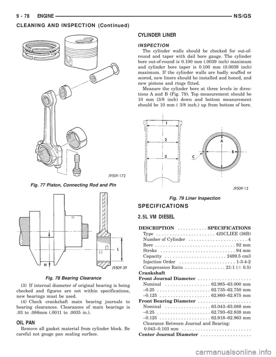
Compare internal diameters of connecting rod with
crankshaft journal diameter. Maximum clearance
between connecting rod and crankshaft journals .022
to .076mm (.0008 to .0029 in.) (Fig. 78).
CRANKSHAFT MAIN BEARING
INSPECTION
(1) Fit main bearing carriers together and torque
to 42 N´m (31 ft. lbs.)
(2) Check internal diameter of bearings.
Fig. 75 Checking Rotor Clearance
Fig. 76 Connecting Rod Identification
NS/GSENGINE 9 - 77
CLEANING AND INSPECTION (Continued)
Page 1256 of 1938
(3) If internal diameter of original bearing is being
checked and figures are not within specifications,
new bearings must be used.
(4) Check crankshaft main bearing journals to
bearing clearances. Clearances of main bearings is
.03 to .088mm (.0011 to .0035 in.).
OIL PAN
Remove all gasket material from cylinder block. Be
careful not gouge pan sealing surface.
CYLINDER LINER
INSPECTION
The cylinder walls should be checked for out-of-
round and taper with dail bore gauge. The cylinder
bore out-of-round is 0.100 mm (.0039 inch) maximum
and cylinder bore taper is 0.100 mm (0.0039 inch)
maximum. If the cylinder walls are badly scuffed or
scored, new liners should be installed and honed, and
new pistons and rings fitted.
Measure the cylinder bore at three levels in direc-
tions A and B (Fig. 79). Top measurement should be
10 mm (3/8 inch) down and bottom measurement
should be 10 mm ( 3/8 inch.) up from bottom of bore.
SPECIFICATIONS
2.5L VM DIESEL
DESCRIPTION...........SPECIFICATIONS
Type ......................425CLIEE (36B)
Number of Cylinder......................4
Bore..............................92mm
Stroke............................94mm
Capacity.......................2499.5 cm3
Injection Order.....................1-3-4-2
Compression Ratio...............21:1 (60.5)
Crankshaft
Front Journal Diameter....................
Nominal.................62.985±63.000 mm
±0.25....................62.735±62.750 mm
±0.125...................62.860±62.875 mm
Front Bearing Diameter....................
Nominal.................63.043±63.088 mm
±0.25....................62.793±62.838 mm
±0.125...................62.918±62.963 mm
Clearance Between Journal and Bearing:
0.043±0.103 mm..........................
Center Journal Diameter...................
Fig. 77 Piston, Connecting Rod and Pin
Fig. 78 Bearing Clearance
Fig. 79 Liner Inspection
9 - 78 ENGINENS/GS
CLEANING AND INSPECTION (Continued)
Page 1265 of 1938
CAUTION: When servicing, care must be exercised
not to dent or bend the bellows of the flex-joint.
Should this occur, the flex-joint will eventually fail
and require the catalytic converter be replaced.
DESCRIPTION AND OPERATION
INTAKE/EXHAUST MANIFOLDÐ2.4L ENGINE
The intake manifold is a tuned two-piece alumi-
num casting with individual primary runners leading
from a plenum to the cylinders. The manifold is
designed to boost torque which is desired for excel-
lent engine response and usable power output.
The exhaust manifold is made of nodular cast iron
for strength and high temperatures.
INTAKE/EXHAUST MANIFOLDÐ3.0L ENGINE
The aluminum alloy manifold is a cross type with
long runners to improve air flow. The runners,
attaching below at the cylinder head, also attach
above and support an air plenum. The air plenum
chamber absorbs air pulsations created during the
suction phase of each cylinder.Both exhaust manifolds are a log style made of
ductile cast iron. Exhaust gasses, collected from the
front cylinder bank, leave the front manifold through
an end outlet and are fed through an upper crossover
tube to the rear manifold. The collected exhaust from
both manifolds are combined at the exhaust outlet, to
the exhaust pipe.
INTAKE/EXHAUST MANIFOLDÐ3.3/3.8L ENGINES
The intake manifold is a tuned two-piece semi-per-
manent mold aluminum casting with individual pri-
mary runners leading from a plenum to the
cylinders. The manifold is designed to boost torque in
the 3600 rpm range and contributes to the engine's
broad, flat torque curve, which was desired for excel-
lent engine tractability, response and usable power
output.
The intake manifold is also cored with upper level
EGR passages for balanced cylinder to cylinder EGR
distribution.
The exhaust manifolds are log type with a cross-
over and are attached directly to the cylinder heads.
They are made from nodular cast iron.
DIAGNOSIS AND TESTING
EXHAUST SYSTEM
CONDITION POSSIBLE CAUSES CORRECTION
EXCESSIVE EXHAUST
NOISE (UNDER HOOD)1. Exhaust manifold cracked or broken. 1. Replace manifold.
2. Manifold to cylinder head leak. 2. Tighten manifold and/or replace gasket.
3. EGR Valve to manifold gasket leakage. 3. Tighten fasteners or replace gasket.
4. EGR Valve to EGR tube gasket
leakage.4. Tighten fasteners or replace gasket.
5. EGR tube to manifold tube leakage. 5. Tighten tube nut.
6. Exhaust flex-joint to manifold leak. 6. Tighten joint fasteners and/or replace
gasket.
7. Exhaust flex-joint. 7. Replace catalytic converter assembly.
8. Pipe and shell noise from front exhaust
pipe.8. Characteristic of single wall pipe.
EXCESSIVE EXHAUST
NOISE1. Leak at exhaust pipe joints. 1. Tighten clamps at leaking joints.
2. Burned or rusted out muffler assembly
or exhaust pipe.2. Replace muffler resonator tailpipe
assembly or exhaust pipe with catalytic
converter assembly.
3. Burned or rusted out resonator. 3. Replace muffler resonator tailpipe
assembly.
4. Restriction in exhaust system. 4. Remove restriction, if possible, or
replace as necessary.
5. Converter material in muffler. 5. Replace muffler and converter
assemblies. Check fuel injection and
ignition systems for proper operation.
NSEXHAUST SYSTEM AND INTAKE MANIFOLD 11 - 3
GENERAL INFORMATION (Continued)
Page 1270 of 1938
(2) Tighten intake manifold fasteners in the fol-
lowing sequence (Fig. 16). Torque to 23 N´m (200 in.
lbs.). Repeat this procedure until all bolts are at
specified torque.
(3) Install intake manifold center support bracket
bolts (Y bracket):
²Fastener to block 54 N´m (40 ft. lbs.)
²Fastener to intake 28 N´m (250 in. lbs.)
(4) Install fuel hose quick connector fitting to
chassis tubes.Refer to Fuel Hoses, Clamps and
Quick Connect Fittings in Group 14, Fuel Deliv-
ery.Push the fitting onto the chassis tube until it
clicks into place. Pull on the fitting to ensure com-
plete insertion.
(5) Reverse removal procedures 2 through 12 for
installation.
CAUTION: When using the ASD Fuel System Test,
the ASD relay and fuel pump relay remain energized
for 7 minutes or until the test is stopped, or until
the ignition switch is turned to the Off position.
(6) With the ignition key in ON position, access
the DRB scan tool ASD Fuel System Test to pressur-
ize the fuel system. Check for leaks.
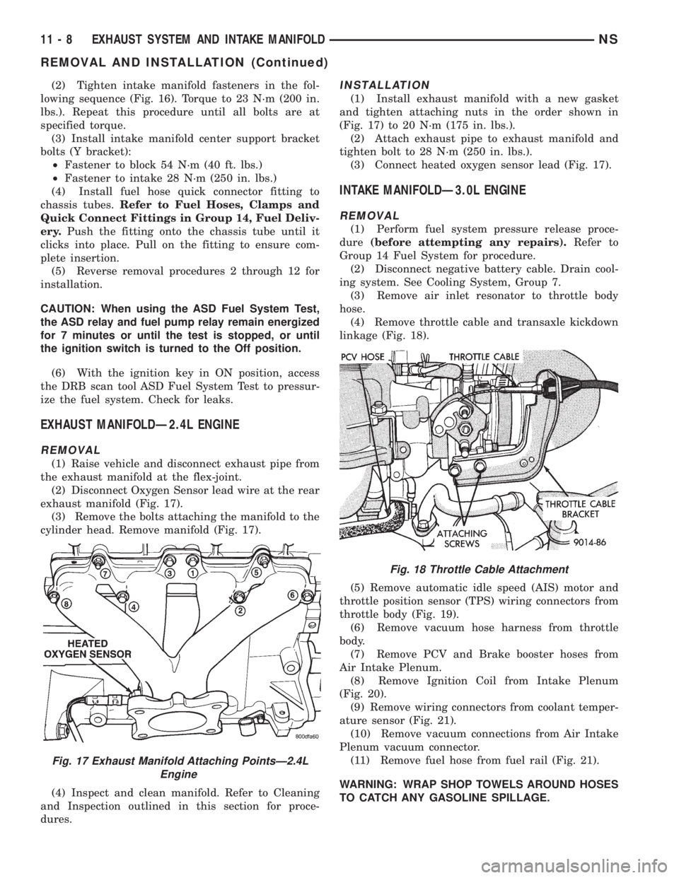
EXHAUST MANIFOLDÐ2.4L ENGINE
REMOVAL
(1) Raise vehicle and disconnect exhaust pipe from
the exhaust manifold at the flex-joint.
(2) Disconnect Oxygen Sensor lead wire at the rear
exhaust manifold (Fig. 17).
(3) Remove the bolts attaching the manifold to the
cylinder head. Remove manifold (Fig. 17).
(4) Inspect and clean manifold. Refer to Cleaning
and Inspection outlined in this section for proce-
dures.
INSTALLATION
(1) Install exhaust manifold with a new gasket
and tighten attaching nuts in the order shown in
(Fig. 17) to 20 N´m (175 in. lbs.).
(2) Attach exhaust pipe to exhaust manifold and
tighten bolt to 28 N´m (250 in. lbs.).
(3) Connect heated oxygen sensor lead (Fig. 17).
INTAKE MANIFOLDÐ3.0L ENGINE
REMOVAL
(1) Perform fuel system pressure release proce-
dure(before attempting any repairs).Refer to
Group 14 Fuel System for procedure.
(2) Disconnect negative battery cable. Drain cool-
ing system. See Cooling System, Group 7.
(3) Remove air inlet resonator to throttle body
hose.
(4) Remove throttle cable and transaxle kickdown
linkage (Fig. 18).
(5) Remove automatic idle speed (AIS) motor and
throttle position sensor (TPS) wiring connectors from
throttle body (Fig. 19).
(6) Remove vacuum hose harness from throttle
body.
(7) Remove PCV and Brake booster hoses from
Air Intake Plenum.
(8) Remove Ignition Coil from Intake Plenum
(Fig. 20).
(9) Remove wiring connectors from coolant temper-
ature sensor (Fig. 21).
(10) Remove vacuum connections from Air Intake
Plenum vacuum connector.
(11) Remove fuel hose from fuel rail (Fig. 21).
WARNING: WRAP SHOP TOWELS AROUND HOSES
TO CATCH ANY GASOLINE SPILLAGE.
Fig. 17 Exhaust Manifold Attaching PointsÐ2.4L
Engine
Fig. 18 Throttle Cable Attachment
11 - 8 EXHAUST SYSTEM AND INTAKE MANIFOLDNS
REMOVAL AND INSTALLATION (Continued)
Page 1273 of 1938
(10) Connect fuel line to fuel rail (Fig. 21). Torque
hose clamps to 1 N´m (10 in. lbs.).
(11) Connect vacuum harness to air intake ple-
num.
(12) Connect and coolant temperature sensor elec-
trical connector to sensor (Fig. 21).
(13) Connect PCV and brake booster supply hose
to intake plenum.
(14) Connect automatic idle speed (AIS) motor
and throttle position sensor (TPS) electrical connec-
tors (Fig. 19).
(15) Connect vacuum vapor harness to throttle
body (Fig. 19).
(16) Install throttle cable and transaxle kickdown
linkage (Fig. 18).
(17) Install air inlet resonator hose assembly to
throttle body.
(18) Install radiator to thermostat housing hose
and heater hose to heater pipe nipple.
(19) Fill cooling system. Refer to Filling the Cool-
ing System outlined in Group 7 Cooling System for
procedure.
(20) Connect negative battery cable.
(21) With the DRB Scan Tool use ASD Fuel Sys-
tem Test to pressurize system to check for leaks.
CAUTION: When using the ASD Fuel System Test,
The Auto Shutdown (ASD) Relay will remain ener-
gized for 7 minutes or until the ignition switch is
turned to the OFF position, or Stop All Test is
selected.
EXHAUST MANIFOLDÐ3.0L ENGINE
REMOVAL
(1) Raise vehicle and disconnect exhaust pipe
from rear (cowl side) exhaust manifold at the flex-
joint.(2) Disconnect Oxygen Sensor lead wire at the
rear exhaust manifold (Fig. 28).
(3) Remove bolts attaching cross-over pipe to
manifold (Fig. 30).
(4) Remove rear heat shield (Fig. 29).
(5) Remove nuts attaching rear manifold to cylin-
der head and remove manifold.
(6) Lower vehicle and remove screws attaching
front heat shield to front manifold (Fig. 31).
(7) Remove bolts fastening crossover pipe to front
exhaust manifold and nuts fastening manifold to cyl-
inder head. Remove assemblies.
(8) Inspect and clean manifolds. Refer to Cleaning
and Inspection outlined in this section for proce-
dures.
INSTALLATION
Install the gaskets with the numbers 1-3-5
embossed on the top on the rear bank and those with
numbers 2-4-6 on the front (Radiator side) bank (Fig.
32).
(1) Install rear exhaust manifold and tighten
attaching nuts to 20 N´m (175 in. lbs.).
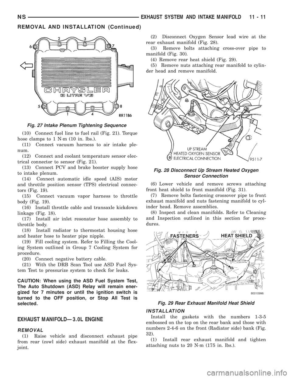
Fig. 27 Intake Plenum Tightening Sequence
Fig. 28 Disconnect Up Stream Heated Oxygen
Sensor Connection
Fig. 29 Rear Exhaust Manifold Heat Shield
NSEXHAUST SYSTEM AND INTAKE MANIFOLD 11 - 11
REMOVAL AND INSTALLATION (Continued)
Page 1277 of 1938
(5) Make sure the injector holes are clean and all
plugs have been removed.
(6) Lube injector O-ring with a drop of clean
engine oil to ease installation.(7) Put the tip of each injector into their ports.
Push the assembly into place until the injectors are
seated in the ports (Fig. 41).
(8) Install the fuel rail attaching bolts and torque
to 22 N´m (200 in. lbs.) (Fig. 39).
(9) Install fuel tube retaining bracket screw and
torque to 4 N´m (35 in. lbs.) (Fig. 39).
(10) Connect cam sensor and coolant temperature
sensor (Fig. 40).
(11) Remove covering on lower intake manifold
and clean surface.
(12) Place the new intake manifold gasket on
lower manifold. Put upper manifold into place and
install bolts and nuts finger tight.
NOTE: At no time should the studs be replaced
with a bolt and washer.
(13) Install the generator bracket to intake mani-
fold bolt and the cylinder head to intake manifold
strut bolts. (Do not torque.)
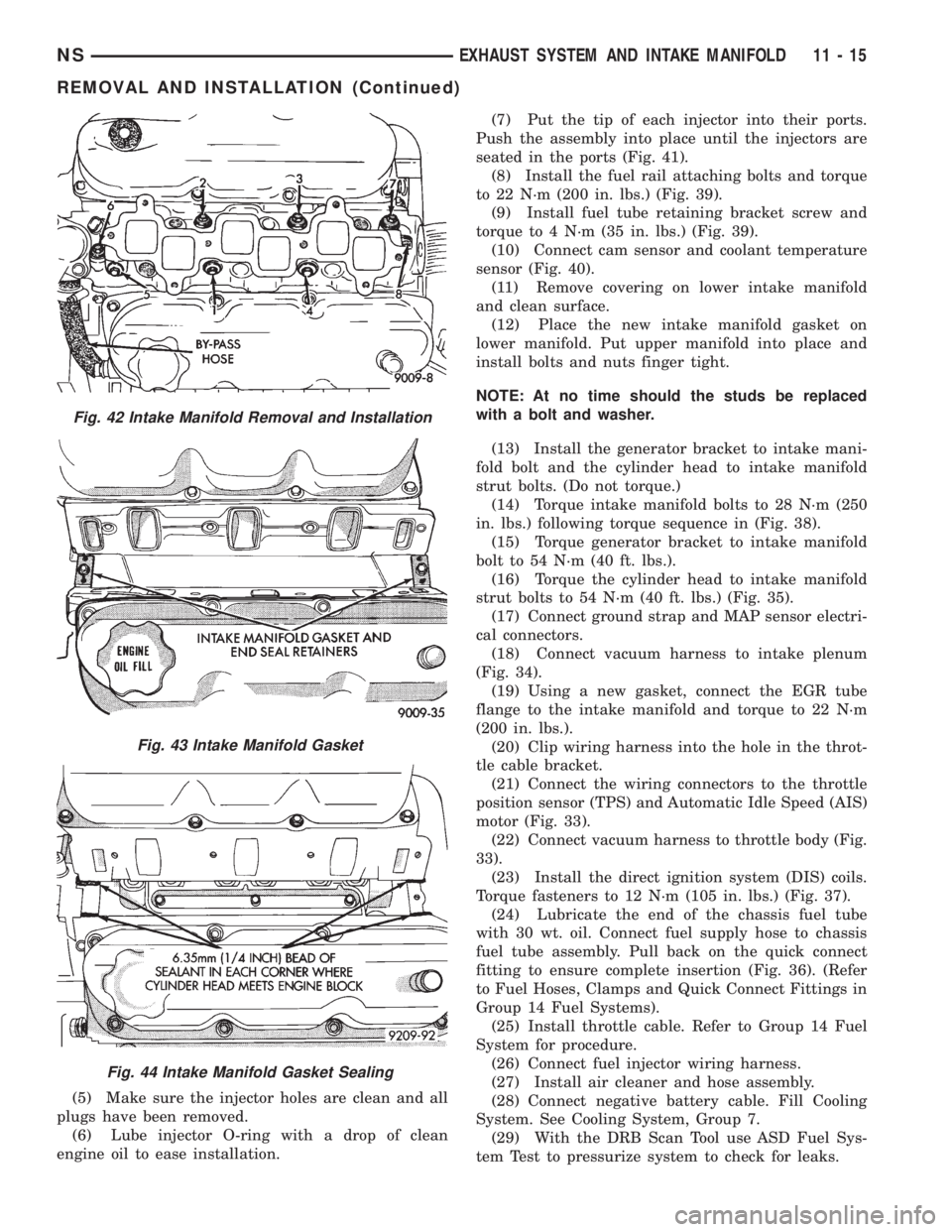
(14) Torque intake manifold bolts to 28 N´m (250
in. lbs.) following torque sequence in (Fig. 38).
(15) Torque generator bracket to intake manifold
bolt to 54 N´m (40 ft. lbs.).
(16) Torque the cylinder head to intake manifold
strut bolts to 54 N´m (40 ft. lbs.) (Fig. 35).
(17) Connect ground strap and MAP sensor electri-
cal connectors.
(18) Connect vacuum harness to intake plenum
(Fig. 34).
(19) Using a new gasket, connect the EGR tube
flange to the intake manifold and torque to 22 N´m
(200 in. lbs.).
(20) Clip wiring harness into the hole in the throt-
tle cable bracket.
(21) Connect the wiring connectors to the throttle
position sensor (TPS) and Automatic Idle Speed (AIS)
motor (Fig. 33).
(22) Connect vacuum harness to throttle body (Fig.
33).
(23) Install the direct ignition system (DIS) coils.
Torque fasteners to 12 N´m (105 in. lbs.) (Fig. 37).
(24) Lubricate the end of the chassis fuel tube
with 30 wt. oil. Connect fuel supply hose to chassis
fuel tube assembly. Pull back on the quick connect
fitting to ensure complete insertion (Fig. 36). (Refer
to Fuel Hoses, Clamps and Quick Connect Fittings in
Group 14 Fuel Systems).
(25) Install throttle cable. Refer to Group 14 Fuel
System for procedure.
(26) Connect fuel injector wiring harness.
(27) Install air cleaner and hose assembly.
(28) Connect negative battery cable. Fill Cooling
System. See Cooling System, Group 7.
(29) With the DRB Scan Tool use ASD Fuel Sys-
tem Test to pressurize system to check for leaks.
Fig. 42 Intake Manifold Removal and Installation
Fig. 43 Intake Manifold Gasket
Fig. 44 Intake Manifold Gasket Sealing
NSEXHAUST SYSTEM AND INTAKE MANIFOLD 11 - 15
REMOVAL AND INSTALLATION (Continued)
Page 1298 of 1938
FUEL DELIVERY SYSTEM
INDEX
page page
DESCRIPTION AND OPERATION
FUEL DELIVERY SYSTEM.................. 4
FUEL INJECTORS........................ 5
FUEL LEVEL SENSOR..................... 5
FUEL PRESSURE REGULATOR.............. 5
FUEL PUMP MODULE..................... 4
FUEL TANK............................. 5
PRESSURE-VACUUM FILLER CAP........... 6
QUICK-CONNECT FITTINGS................ 6
DIAGNOSIS AND TESTING
FUEL INJECTORS........................ 9
FUEL LEVEL SENSOR..................... 9
FUEL PUMP PRESSURE TEST 2.4/3.3/3.8L..... 6
SERVICE PROCEDURES
FUEL SYSTEM PRESSURE RELEASE
PROCEDUREÐ2.4/3.3/3.8L............... 11
FUEL SYSTEM PRESSURE RELEASE
PROCEDUREÐ3.0L ENGINE............. 11
HOSES AND CLAMPS.................... 12QUICK-CONNECT FITTINGS............... 12
REMOVAL AND INSTALLATION
ACCELERATOR PEDAL................... 26
FUEL FILTER........................... 12
FUEL INJECTOR RAILÐ2.4L............... 18
FUEL INJECTOR RAILÐ3.0L............... 19
FUEL INJECTOR RAILÐ3.3/3.8L............ 21
FUEL INJECTORSÐ3.0L.................. 25
FUEL INJECTORÐ2.4L................... 24
FUEL INJECTORÐ3.3/3.8L................. 26
FUEL LEVEL SENSOR.................... 15
FUEL PRESSURE REGULATOR............. 14
FUEL PUMP INLET STRAINER............. 15
FUEL PUMP MODULE.................... 13
FUEL TANK............................ 17
THROTTLE CABLE...................... 27
SPECIFICATIONS
FUEL TANK CAPACITY................... 28
TORQUE.............................. 28
DESCRIPTION AND OPERATION
FUEL DELIVERY SYSTEM
The front wheel drive van uses a plastic fuel tank
located on the left side of the vehicle.
The Fuel Delivery System consists of: the electric
fuel pump module, fuel filter, tubes/lines/hoses, fuel
rail, and fuel injectors.
The in-tank fuel pump module contains the fuel
pump and pressure regulator. The pump is serviced
as part of the fuel pump module. Refer to Fuel Pump
Module.
The fuel filter is a replaceable in-line filter. The fil-
ter attaches to a bracket mounted on top of the fuel
tank. Refer to the Maintenance Schedules in the
Introduction section of this manual for recommended
fuel filter replacement intervals.
A returnless fuel system is used on all vehicles.
Fuel is returned through the fuel pump module and
back to the fuel tank. A separate fuel return line
from the tank to the engine is no longer used.
FUEL PUMP MODULE
The fuel pump module is installed in the top of the
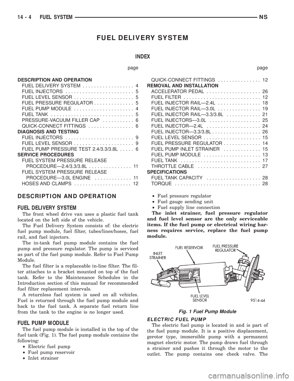
fuel tank (Fig. 1). The fuel pump module contains the
following:
²Electric fuel pump
²Fuel pump reservoir
²Inlet strainer²Fuel pressure regulator
²Fuel gauge sending unit
²Fuel supply line connection
The inlet strainer, fuel pressure regulator
and fuel level sensor are the only serviceable
items. If the fuel pump or electrical wiring har-
ness requires service, replace the fuel pump
module.
ELECTRIC FUEL PUMP
The electric fuel pump is located in and is part of
the fuel pump module. It is a positive displacement,
gerotor type, immersible pump with a permanent
magnet electric motor. The pump draws fuel through
a strainer and pushes it through the motor to the
outlet. The pump contains one check valve. The
Fig. 1 Fuel Pump Module
14 - 4 FUEL SYSTEMNS