1996 CHRYSLER VOYAGER check engine
[x] Cancel search: check enginePage 1183 of 1938
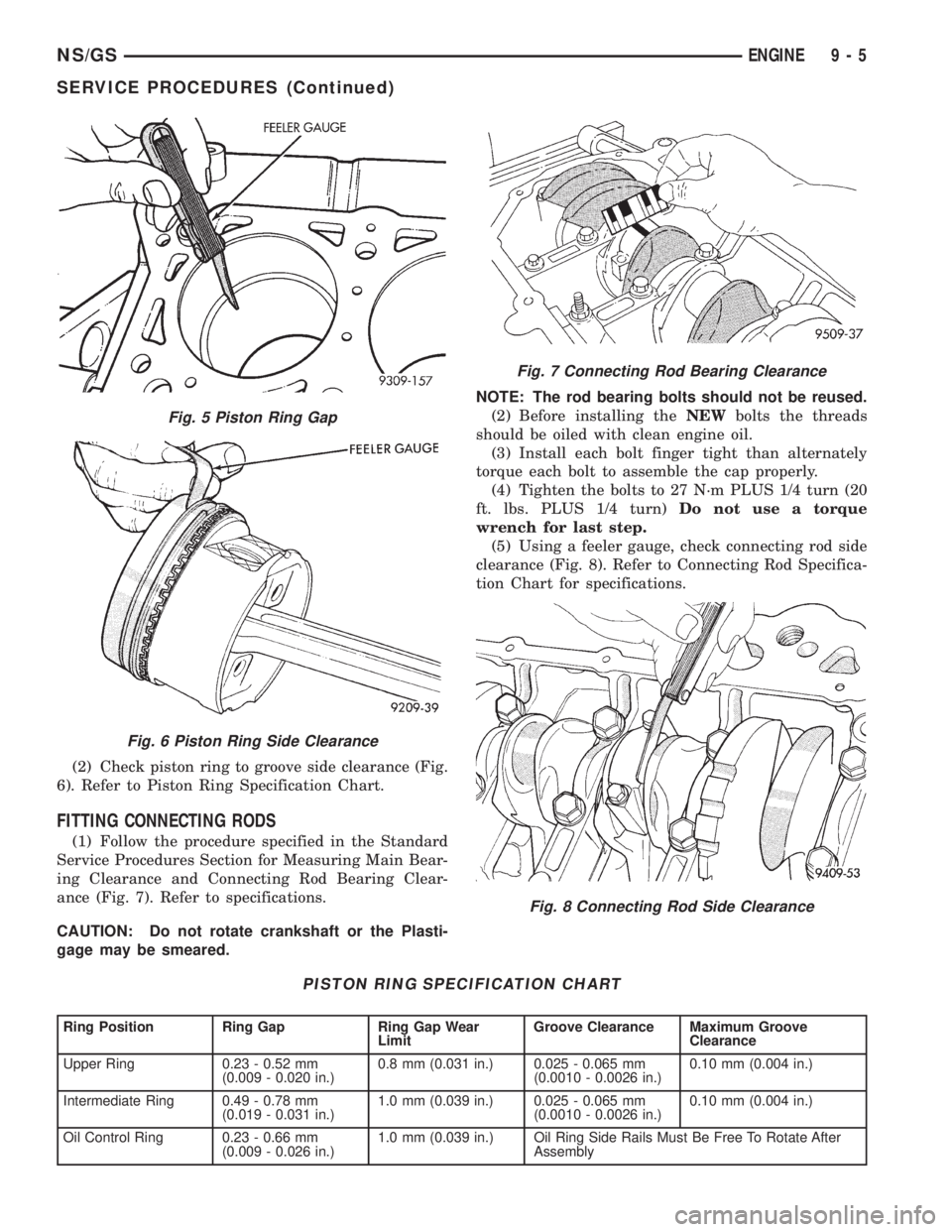
(2) Check piston ring to groove side clearance (Fig.
6). Refer to Piston Ring Specification Chart.
FITTING CONNECTING RODS
(1) Follow the procedure specified in the Standard
Service Procedures Section for Measuring Main Bear-
ing Clearance and Connecting Rod Bearing Clear-
ance (Fig. 7). Refer to specifications.
CAUTION: Do not rotate crankshaft or the Plasti-
gage may be smeared.NOTE: The rod bearing bolts should not be reused.
(2) Before installing theNEWbolts the threads
should be oiled with clean engine oil.
(3) Install each bolt finger tight than alternately
torque each bolt to assemble the cap properly.
(4) Tighten the bolts to 27 N´m PLUS 1/4 turn (20
ft. lbs. PLUS 1/4 turn)Do not use a torque
wrench for last step.
(5) Using a feeler gauge, check connecting rod side
clearance (Fig. 8). Refer to Connecting Rod Specifica-
tion Chart for specifications.
Fig. 5 Piston Ring Gap
Fig. 6 Piston Ring Side Clearance
PISTON RING SPECIFICATION CHART
Ring Position Ring Gap Ring Gap Wear
LimitGroove Clearance Maximum Groove
Clearance
Upper Ring 0.23 - 0.52 mm
(0.009 - 0.020 in.)0.8 mm (0.031 in.) 0.025 - 0.065 mm
(0.0010 - 0.0026 in.)0.10 mm (0.004 in.)
Intermediate Ring 0.49 - 0.78 mm
(0.019 - 0.031 in.)1.0 mm (0.039 in.) 0.025 - 0.065 mm
(0.0010 - 0.0026 in.)0.10 mm (0.004 in.)
Oil Control Ring 0.23 - 0.66 mm
(0.009 - 0.026 in.)1.0 mm (0.039 in.) Oil Ring Side Rails Must Be Free To Rotate After
Assembly
Fig. 7 Connecting Rod Bearing Clearance
Fig. 8 Connecting Rod Side Clearance
NS/GSENGINE 9 - 5
SERVICE PROCEDURES (Continued)
Page 1184 of 1938
FITTING CRANKSHAFT BEARINGS
Refer to Measuring Main Bearing Clearance in
Standard Service Procedures. Refer to Crankshaft
Specification Chart for specifications.
CRANKSHAFT END PLAY
DIAL INDICATOR METHOD
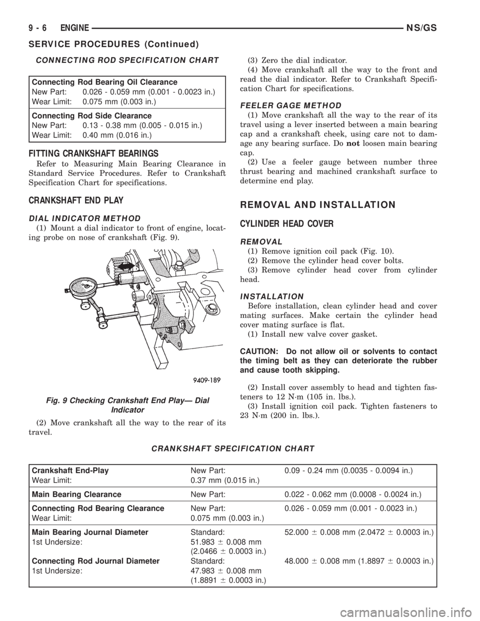
(1) Mount a dial indicator to front of engine, locat-
ing probe on nose of crankshaft (Fig. 9).
(2) Move crankshaft all the way to the rear of its
travel.(3) Zero the dial indicator.
(4) Move crankshaft all the way to the front and
read the dial indicator. Refer to Crankshaft Specifi-
cation Chart for specifications.
FEELER GAGE METHOD
(1) Move crankshaft all the way to the rear of its
travel using a lever inserted between a main bearing
cap and a crankshaft cheek, using care not to dam-
age any bearing surface. Donotloosen main bearing
cap.
(2) Use a feeler gauge between number three
thrust bearing and machined crankshaft surface to
determine end play.
REMOVAL AND INSTALLATION
CYLINDER HEAD COVER
REMOVAL
(1) Remove ignition coil pack (Fig. 10).
(2) Remove the cylinder head cover bolts.
(3) Remove cylinder head cover from cylinder
head.
INSTALLATION
Before installation, clean cylinder head and cover
mating surfaces. Make certain the cylinder head
cover mating surface is flat.
(1) Install new valve cover gasket.
CAUTION: Do not allow oil or solvents to contact
the timing belt as they can deteriorate the rubber
and cause tooth skipping.
(2) Install cover assembly to head and tighten fas-
teners to 12 N´m (105 in. lbs.).
(3) Install ignition coil pack. Tighten fasteners to
23 N´m (200 in. lbs.).
CONNECTING ROD SPECIFICATION CHART
Connecting Rod Bearing Oil Clearance
New Part: 0.026 - 0.059 mm (0.001 - 0.0023 in.)
Wear Limit: 0.075 mm (0.003 in.)
Connecting Rod Side Clearance
New Part: 0.13 - 0.38 mm (0.005 - 0.015 in.)
Wear Limit: 0.40 mm (0.016 in.)
CRANKSHAFT SPECIFICATION CHART
Crankshaft End-PlayNew Part: 0.09 - 0.24 mm (0.0035 - 0.0094 in.)
Wear Limit: 0.37 mm (0.015 in.)
Main Bearing ClearanceNew Part: 0.022 - 0.062 mm (0.0008 - 0.0024 in.)
Connecting Rod Bearing ClearanceNew Part: 0.026 - 0.059 mm (0.001 - 0.0023 in.)
Wear Limit: 0.075 mm (0.003 in.)
Main Bearing Journal DiameterStandard: 52.00060.008 mm (2.047260.0003 in.)
1st Undersize: 51.98360.008 mm
(2.046660.0003 in.)
Connecting Rod Journal DiameterStandard: 48.00060.008 mm (1.889760.0003 in.)
1st Undersize: 47.98360.008 mm
(1.889160.0003 in.)
Fig. 9 Checking Crankshaft End PlayÐ Dial
Indicator
9 - 6 ENGINENS/GS
SERVICE PROCEDURES (Continued)
Page 1185 of 1938
SPARK PLUG TUBE
(1) Remove valve cover. Refer to procedure out-
lined in this section.
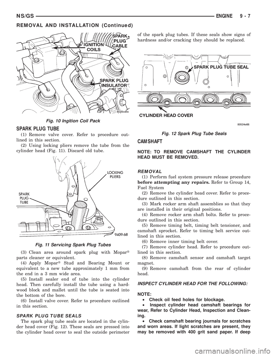
(2) Using locking pliers remove the tube from the
cylinder head (Fig. 11). Discard old tube.
(3) Clean area around spark plug with Mopart
parts cleaner or equivalent.
(4) Apply MopartStud and Bearing Mount or
equivalent to a new tube approximately 1 mm from
theendina3mmwide area.
(5) Install sealer end of tube into the cylinder
head. Then carefully install the tube using a hard-
wood block and mallet until the tube is seated into
the bottom of the bore.
(6) Install valve cover. Refer to procedure outlined
in this section.
SPARK PLUG TUBE SEALS
The spark plug tube seals are located in the cylin-
der head cover (Fig. 12). These seals are pressed into
the cylinder head cover to seal the outside perimeterof the spark plug tubes. If these seals show signs of
hardness and/or cracking they should be replaced.
CAMSHAFT
NOTE: TO REMOVE CAMSHAFT THE CYLINDER
HEAD MUST BE REMOVED.
REMOVAL
(1) Perform fuel system pressure release procedure
before attempting any repairs.Refer to Group 14,
Fuel System
(2) Remove the cylinder head cover. Refer to proce-
dure outlined in this section.
(3) Mark rocker arm shaft assemblies so that they
are installed in their original positions.
(4) Remove rocker arm shaft bolts. Refer to proce-
dure outlined in this section.
(5) Remove timing belt, timing belt tensioner, and
camshaft sprocket. Refer to timing belt service out-
lined in this section.
(6) Remove inner timing belt cover.
(7) Remove cylinder head. Refer to procedure out-
lined in this section.
(8) Remove camshaft sensor and camshaft target
magnet.
(9) Remove camshaft from the rear of cylinder
head.
INSPECT CYLINDER HEAD FOR THE FOLLOWING:
NOTE:
²Check oil feed holes for blockage.
²Inspect cylinder head camshaft bearings for
wear, Refer to Cylinder Head, Inspection and Clean-
ing.
²Check camshaft bearing journals for scratches
and worn areas. If light scratches are present, they
may be removed with 400 grit sand paper. If deep
Fig. 10 Ingition Coil Pack
Fig. 11 Servicing Spark Plug Tubes
Fig. 12 Spark Plug Tube Seals
NS/GSENGINE 9 - 7
REMOVAL AND INSTALLATION (Continued)
Page 1186 of 1938
scratches are present, replace the camshaft and
check the cylinder head for damage. Replace the
cylinder head if worn or damaged. Check the lobes
for pitting and wear. If the lobes show signs of
wear, check the corresponding rocker arm roller for
wear or damage. Replace rocker arm/hydraulic lash
adjuster if worn or damaged. If lobes show signs of
pitting on the nose, flank or base circle; replace the
camshaft.
INSTALLATION
(1) Lubricate the camshaft journals with oil and
install camshaftwithoutrocker arm assemblies
installed.
(2) Install camshaft target magnet into the end of
the camshaft. Tighten mounting screw to 3.4 N´m (30
in. lbs.).
(3) Install camshaft position sensor and tighten
mounting screws to 9 N´m (80 in. lbs.).
(4) Measure camshaft end play using the following
procedure:
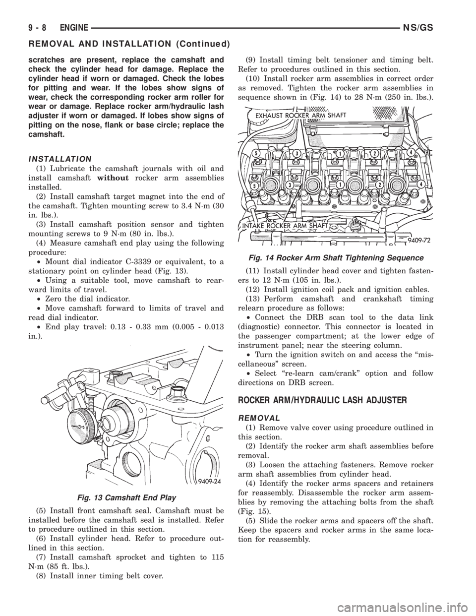
²Mount dial indicator C-3339 or equivalent, to a
stationary point on cylinder head (Fig. 13).
²Using a suitable tool, move camshaft to rear-
ward limits of travel.
²Zero the dial indicator.
²Move camshaft forward to limits of travel and
read dial indicator.
²End play travel: 0.13 - 0.33 mm (0.005 - 0.013
in.).
(5) Install front camshaft seal. Camshaft must be
installed before the camshaft seal is installed. Refer
to procedure outlined in this section.
(6) Install cylinder head. Refer to procedure out-
lined in this section.
(7) Install camshaft sprocket and tighten to 115
N´m (85 ft. lbs.).
(8) Install inner timing belt cover.(9) Install timing belt tensioner and timing belt.
Refer to procedures outlined in this section.
(10) Install rocker arm assemblies in correct order
as removed. Tighten the rocker arm assemblies in
sequence shown in (Fig. 14) to 28 N´m (250 in. lbs.).
(11) Install cylinder head cover and tighten fasten-
ers to 12 N´m (105 in. lbs.).
(12) Install ignition coil pack and ignition cables.
(13) Perform camshaft and crankshaft timing
relearn procedure as follows:
²Connect the DRB scan tool to the data link
(diagnostic) connector. This connector is located in
the passenger compartment; at the lower edge of
instrument panel; near the steering column.
²Turn the ignition switch on and access the ªmis-
cellaneousº screen.
²Select ªre-learn cam/crankº option and follow
directions on DRB screen.
ROCKER ARM/HYDRAULIC LASH ADJUSTER
REMOVAL
(1) Remove valve cover using procedure outlined in
this section.
(2) Identify the rocker arm shaft assemblies before
removal.
(3) Loosen the attaching fasteners. Remove rocker
arm shaft assemblies from cylinder head.
(4) Identify the rocker arms spacers and retainers
for reassembly. Disassemble the rocker arm assem-
blies by removing the attaching bolts from the shaft
(Fig. 15).
(5) Slide the rocker arms and spacers off the shaft.
Keep the spacers and rocker arms in the same loca-
tion for reassembly.
Fig. 13 Camshaft End Play
Fig. 14 Rocker Arm Shaft Tightening Sequence
9 - 8 ENGINENS/GS
REMOVAL AND INSTALLATION (Continued)
Page 1187 of 1938
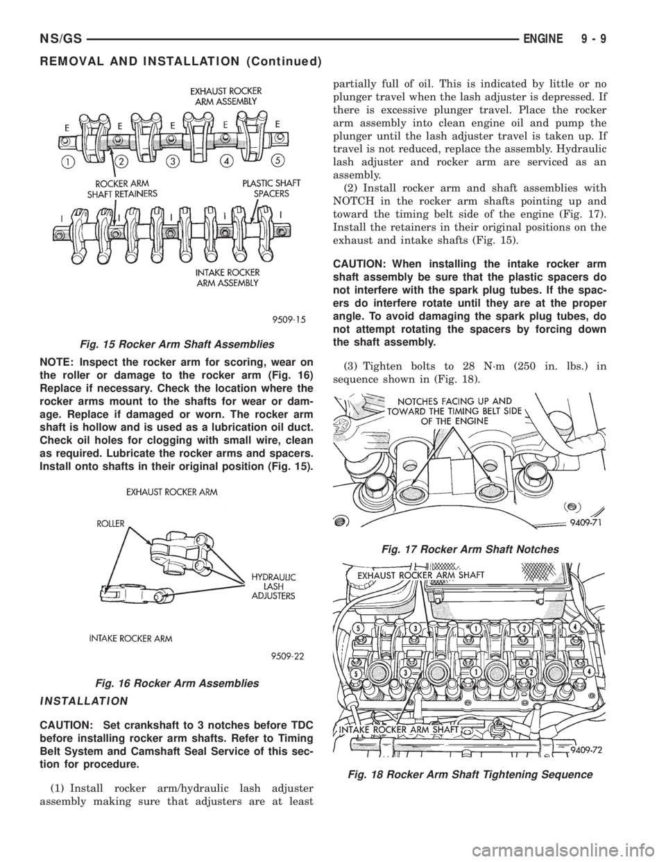
NOTE: Inspect the rocker arm for scoring, wear on
the roller or damage to the rocker arm (Fig. 16)
Replace if necessary. Check the location where the
rocker arms mount to the shafts for wear or dam-
age. Replace if damaged or worn. The rocker arm
shaft is hollow and is used as a lubrication oil duct.
Check oil holes for clogging with small wire, clean
as required. Lubricate the rocker arms and spacers.
Install onto shafts in their original position (Fig. 15).
INSTALLATION
CAUTION: Set crankshaft to 3 notches before TDC
before installing rocker arm shafts. Refer to Timing
Belt System and Camshaft Seal Service of this sec-
tion for procedure.
(1) Install rocker arm/hydraulic lash adjuster
assembly making sure that adjusters are at leastpartially full of oil. This is indicated by little or no
plunger travel when the lash adjuster is depressed. If
there is excessive plunger travel. Place the rocker
arm assembly into clean engine oil and pump the
plunger until the lash adjuster travel is taken up. If
travel is not reduced, replace the assembly. Hydraulic
lash adjuster and rocker arm are serviced as an
assembly.
(2) Install rocker arm and shaft assemblies with
NOTCH in the rocker arm shafts pointing up and
toward the timing belt side of the engine (Fig. 17).
Install the retainers in their original positions on the
exhaust and intake shafts (Fig. 15).
CAUTION: When installing the intake rocker arm
shaft assembly be sure that the plastic spacers do
not interfere with the spark plug tubes. If the spac-
ers do interfere rotate until they are at the proper
angle. To avoid damaging the spark plug tubes, do
not attempt rotating the spacers by forcing down
the shaft assembly.
(3) Tighten bolts to 28 N´m (250 in. lbs.) in
sequence shown in (Fig. 18).
Fig. 15 Rocker Arm Shaft Assemblies
Fig. 16 Rocker Arm Assemblies
Fig. 17 Rocker Arm Shaft Notches
Fig. 18 Rocker Arm Shaft Tightening Sequence
NS/GSENGINE 9 - 9
REMOVAL AND INSTALLATION (Continued)
Page 1189 of 1938
(13) Remove timing belt and camshaft sprocket.
Refer to procedure outlined in this section.
(14) Remove rocker arm shaft assemblies.
(15) Remove cylinder head bolts.
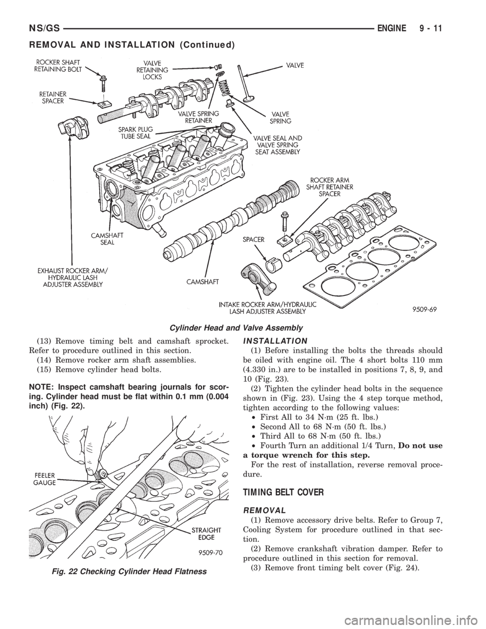
NOTE: Inspect camshaft bearing journals for scor-
ing. Cylinder head must be flat within 0.1 mm (0.004
inch) (Fig. 22).INSTALLATION
(1) Before installing the bolts the threads should
be oiled with engine oil. The 4 short bolts 110 mm
(4.330 in.) are to be installed in positions 7, 8, 9, and
10 (Fig. 23).
(2) Tighten the cylinder head bolts in the sequence
shown in (Fig. 23). Using the 4 step torque method,
tighten according to the following values:
²First All to 34 N´m (25 ft. lbs.)
²Second All to 68 N´m (50 ft. lbs.)
²Third All to 68 N´m (50 ft. lbs.)
²Fourth Turn an additional 1/4 Turn,Do not use
a torque wrench for this step.
For the rest of installation, reverse removal proce-
dure.
TIMING BELT COVER
REMOVAL
(1) Remove accessory drive belts. Refer to Group 7,
Cooling System for procedure outlined in that sec-
tion.
(2) Remove crankshaft vibration damper. Refer to
procedure outlined in this section for removal.
(3) Remove front timing belt cover (Fig. 24).
Cylinder Head and Valve Assembly
Fig. 22 Checking Cylinder Head Flatness
NS/GSENGINE 9 - 11
REMOVAL AND INSTALLATION (Continued)
Page 1191 of 1938
INSTALLATION
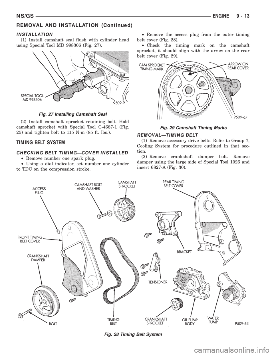
(1) Install camshaft seal flush with cylinder head
using Special Tool MD 998306 (Fig. 27).
(2) Install camshaft sprocket retaining bolt. Hold
camshaft sprocket with Special Tool C-4687-1 (Fig.
25) and tighten bolt to 115 N´m (85 ft. lbs.).
TIMING BELT SYSTEM
CHECKING BELT TIMINGÐCOVER INSTALLED
²Remove number one spark plug.
²Using a dial indicator, set number one cylinder
to TDC on the compression stroke.²Remove the access plug from the outer timing
belt cover (Fig. 28).
²Check the timing mark on the camshaft
sprocket, it should align with the arrow on the rear
belt cover (Fig. 29).
REMOVALÐTIMING BELT
(1) Remove accessory drive belts. Refer to Group 7,
Cooling System for procedure outlined in that sec-
tion.
(2) Remove crankshaft damper bolt. Remove
damper using the large side of Special Tool 1026 and
insert 6827-A (Fig. 30).
Fig. 27 Installing Camshaft Seal
Fig. 28 Timing Belt System
Fig. 29 Camshaft Timing Marks
NS/GSENGINE 9 - 13
REMOVAL AND INSTALLATION (Continued)
Page 1193 of 1938
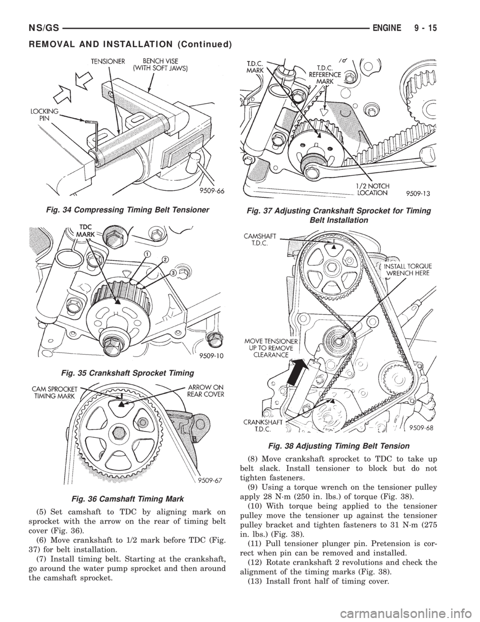
(5) Set camshaft to TDC by aligning mark on
sprocket with the arrow on the rear of timing belt
cover (Fig. 36).
(6) Move crankshaft to 1/2 mark before TDC (Fig.
37) for belt installation.
(7) Install timing belt. Starting at the crankshaft,
go around the water pump sprocket and then around
the camshaft sprocket.(8) Move crankshaft sprocket to TDC to take up
belt slack. Install tensioner to block but do not
tighten fasteners.
(9) Using a torque wrench on the tensioner pulley
apply 28 N´m (250 in. lbs.) of torque (Fig. 38).
(10) With torque being applied to the tensioner
pulley move the tensioner up against the tensioner
pulley bracket and tighten fasteners to 31 N´m (275
in. lbs.) (Fig. 38).
(11) Pull tensioner plunger pin. Pretension is cor-
rect when pin can be removed and installed.
(12) Rotate crankshaft 2 revolutions and check the
alignment of the timing marks (Fig. 38).
(13) Install front half of timing cover.
Fig. 34 Compressing Timing Belt Tensioner
Fig. 35 Crankshaft Sprocket Timing
Fig. 36 Camshaft Timing Mark
Fig. 37 Adjusting Crankshaft Sprocket for Timing
Belt Installation
Fig. 38 Adjusting Timing Belt Tension
NS/GSENGINE 9 - 15
REMOVAL AND INSTALLATION (Continued)