1996 CHRYSLER VOYAGER width
[x] Cancel search: widthPage 1054 of 1938
ENGINE WITH 5 MAIN BEARINGS
²When checking #1 main bearing shim #2 main
bearing.
²When checking #2 main bearing shim #1 & 3
main bearing.
²When checking #3 main bearing shim #2 & 4
main bearing.
²When checking #4 main bearing shim #3 & 5
main bearing.
²When checking #5 main bearing shim #4 main
bearing.
ENGINE WITH 4 MAIN BEARING
²When checking #1 main bearing shim # 2 main
bearing.
²When checking #2 main bearing shim #1 & #3
main bearing.
²When checking #3 main bearing shim #2 & #4
main bearing.
²When checking #4 main bearing shim #3 main
bearing.
NOTE: REMOVE ALL SHIMS BEFORE REASSEM-
BLING ENGINE
ALTERNATIVE METHOD
The weight of the crankshaft can be supported by a
jack under the counterweight adjacent to the bearing
being checked.
PLASTIGAGE PROCEDURE
(1) Remove oil film from surface to be checked.
Plastigage is soluble in oil.
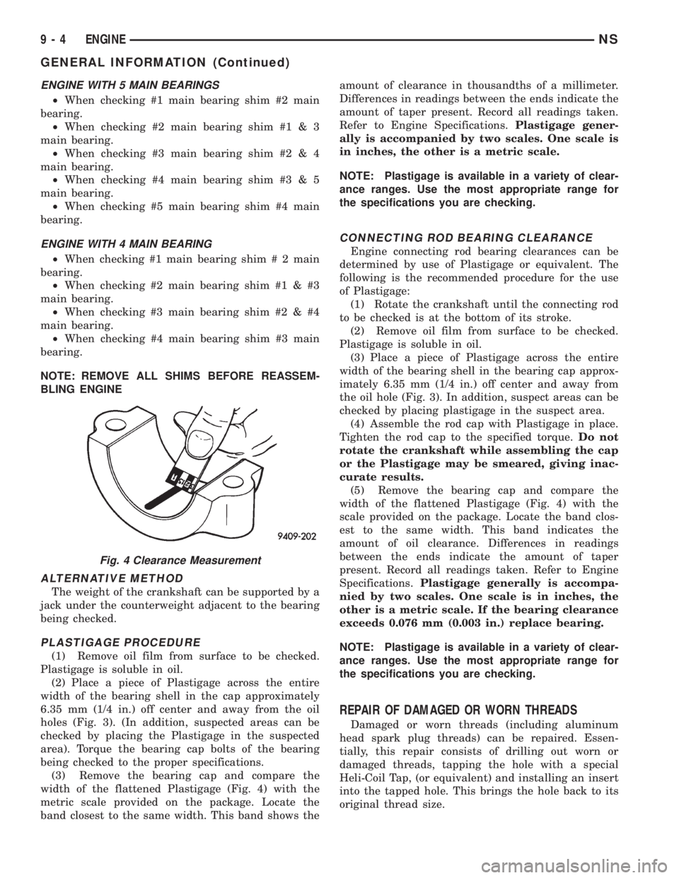
(2) Place a piece of Plastigage across the entire
width of the bearing shell in the cap approximately
6.35 mm (1/4 in.) off center and away from the oil
holes (Fig. 3). (In addition, suspected areas can be
checked by placing the Plastigage in the suspected
area). Torque the bearing cap bolts of the bearing
being checked to the proper specifications.
(3) Remove the bearing cap and compare the
width of the flattened Plastigage (Fig. 4) with the
metric scale provided on the package. Locate the
band closest to the same width. This band shows theamount of clearance in thousandths of a millimeter.
Differences in readings between the ends indicate the
amount of taper present. Record all readings taken.
Refer to Engine Specifications.Plastigage gener-
ally is accompanied by two scales. One scale is
in inches, the other is a metric scale.
NOTE: Plastigage is available in a variety of clear-
ance ranges. Use the most appropriate range for
the specifications you are checking.
CONNECTING ROD BEARING CLEARANCE
Engine connecting rod bearing clearances can be
determined by use of Plastigage or equivalent. The
following is the recommended procedure for the use
of Plastigage:
(1) Rotate the crankshaft until the connecting rod
to be checked is at the bottom of its stroke.
(2) Remove oil film from surface to be checked.
Plastigage is soluble in oil.
(3) Place a piece of Plastigage across the entire
width of the bearing shell in the bearing cap approx-
imately 6.35 mm (1/4 in.) off center and away from
the oil hole (Fig. 3). In addition, suspect areas can be
checked by placing plastigage in the suspect area.
(4) Assemble the rod cap with Plastigage in place.
Tighten the rod cap to the specified torque.Do not
rotate the crankshaft while assembling the cap
or the Plastigage may be smeared, giving inac-
curate results.
(5) Remove the bearing cap and compare the
width of the flattened Plastigage (Fig. 4) with the
scale provided on the package. Locate the band clos-
est to the same width. This band indicates the
amount of oil clearance. Differences in readings
between the ends indicate the amount of taper
present. Record all readings taken. Refer to Engine
Specifications.Plastigage generally is accompa-
nied by two scales. One scale is in inches, the
other is a metric scale. If the bearing clearance
exceeds 0.076 mm (0.003 in.) replace bearing.
NOTE: Plastigage is available in a variety of clear-
ance ranges. Use the most appropriate range for
the specifications you are checking.
REPAIR OF DAMAGED OR WORN THREADS
Damaged or worn threads (including aluminum
head spark plug threads) can be repaired. Essen-
tially, this repair consists of drilling out worn or
damaged threads, tapping the hole with a special
Heli-Coil Tap, (or equivalent) and installing an insert
into the tapped hole. This brings the hole back to its
original thread size.
Fig. 4 Clearance Measurement
9 - 4 ENGINENS
GENERAL INFORMATION (Continued)
Page 1063 of 1938
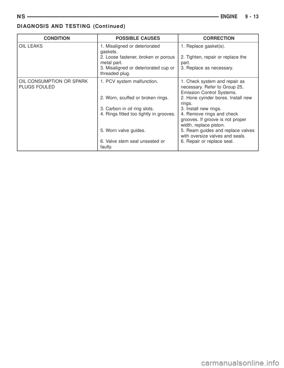
CONDITION POSSIBLE CAUSES CORRECTION
OIL LEAKS 1. Misaligned or deteriorated
gaskets.1. Replace gasket(s).
2. Loose fastener, broken or porous
metal part.2. Tighten, repair or replace the
part.
3. Misaligned or deteriorated cup or
threaded plug.3. Replace as necessary.
OIL CONSUMPTION OR SPARK
PLUGS FOULED1. PCV system malfunction. 1. Check system and repair as
necessary. Refer to Group 25,
Emission Control Systems.
2. Worn, scuffed or broken rings. 2. Hone cyinder bores. Install new
rings.
3. Carbon in oil ring slots. 3. Install new rings.
4. Rings fitted too tightly in grooves. 4. Remove rings and check
grooves. If groove is not proper
width, replace piston.
5. Worn valve guides. 5. Ream guides and replace valves
with oversize valves and seals.
6. Valve stem seal unseated or
faulty.6. Repair or replace seal.
NSENGINE 9 - 13
DIAGNOSIS AND TESTING (Continued)
Page 1068 of 1938
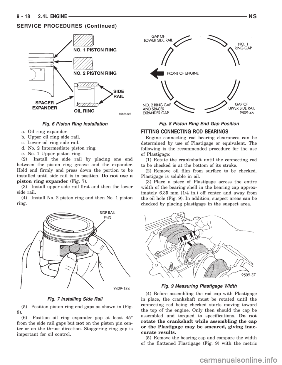
a. Oil ring expander.
b. Upper oil ring side rail.
c. Lower oil ring side rail.
d. No. 2 Intermediate piston ring.
e. No. 1 Upper piston ring.
(2) Install the side rail by placing one end
between the piston ring groove and the expander.
Hold end firmly and press down the portion to be
installed until side rail is in position.Do not use a
piston ring expander(Fig. 7).
(3) Install upper side rail first and then the lower
side rail.
(4) Install No. 2 piston ring and then No. 1 piston
ring.
(5) Position piston ring end gaps as shown in (Fig.
8).
(6) Position oil ring expander gap at least 45É
from the side rail gaps butnoton the piston pin cen-
ter or on the thrust direction. Staggering ring gap is
important for oil control.FITTING CONNECTING ROD BEARINGS
Engine connecting rod bearing clearances can be
determined by use of Plastigage or equivalent. The
following is the recommended procedure for the use
of Plastigage:
(1) Rotate the crankshaft until the connecting rod
to be checked is at the bottom of its stroke.
(2) Remove oil film from surface to be checked.
Plastigage is soluble in oil.
(3) Place a piece of Plastigage across the entire
width of the bearing shell in the bearing cap approx-
imately 6.35 mm (1/4 in.) off center and away from
the oil hole (Fig. 9). In addition, suspect areas can be
checked by placing plastigage in the suspect area.
(4) Before assembling the rod cap with Plastigage
in place, the crankshaft must be rotated until the
connecting rod being checked starts moving toward
the top of the engine. Only then should the cap be
assembled and torqued to specifications.Do not
rotate the crankshaft while assembling the cap
or the Plastigage may be smeared, giving inac-
curate results.
(5) Remove the bearing cap and compare the width
of the flattened Plastigage (Fig. 9) with the metric
Fig. 6 Piston Ring Installation
Fig. 7 Installing Side Rail
Fig. 8 Piston Ring End Gap Position
Fig. 9 Measuring Plastigage Width
9 - 18 2.4L ENGINENS
SERVICE PROCEDURES (Continued)
Page 1069 of 1938
scale provided on the package. Locate the band clos-
est to the same width. This band shows the amount
of clearance in thousandths of a millimeter. Differ-
ences in readings between the ends indicate the
amount of taper present. Record all readings taken.
Refer to Engine Specifications.Plastigage gener-
ally is accompanied by two scales. One scale is
in inches, the other is a metric scale.
(6) Plastigage is available in a variety of clearance
ranges. The 0.025-0.076 mm (.001-.003 in.) is usually
the most appropriate for checking engine bearing
proper specifications.
FITTING MAIN BEARINGS
Refer to the Engine General Information Section
for Measuring Main Bearings. For Crankshaft speci-
fications refer to Crankshaft Specification Chart.
CRANKSHAFT MAIN BEARINGS
The crankshaft is supported in five main bearings.
All upper and lower bearing shells in the crankcase
have oil grooves. The number three lower main
thrust bearing is plain. Crankshaft end play is con-
trolled by a flanged bearing on the number three
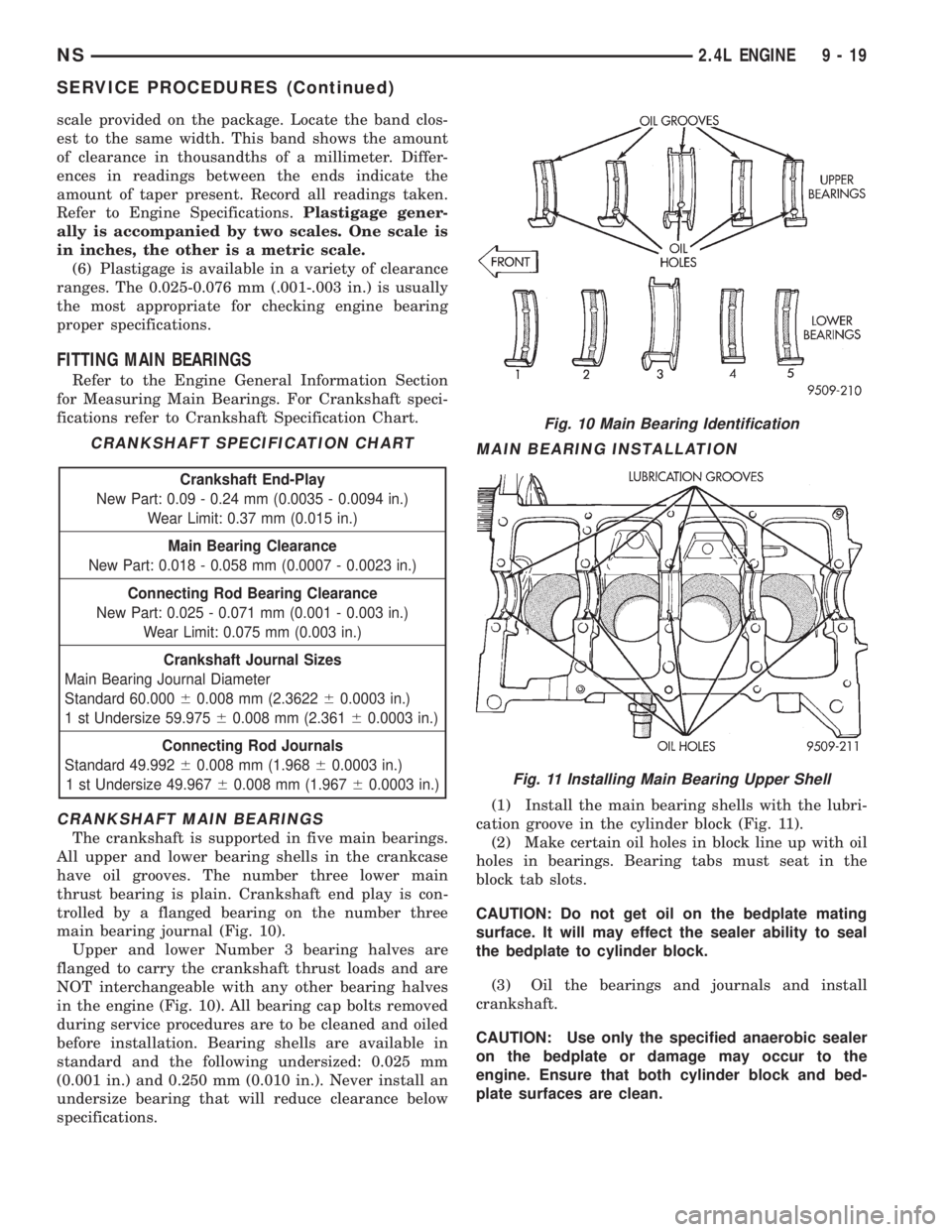
main bearing journal (Fig. 10).
Upper and lower Number 3 bearing halves are
flanged to carry the crankshaft thrust loads and are
NOT interchangeable with any other bearing halves
in the engine (Fig. 10). All bearing cap bolts removed
during service procedures are to be cleaned and oiled
before installation. Bearing shells are available in
standard and the following undersized: 0.025 mm
(0.001 in.) and 0.250 mm (0.010 in.). Never install an
undersize bearing that will reduce clearance below
specifications.
MAIN BEARING INSTALLATION
(1) Install the main bearing shells with the lubri-
cation groove in the cylinder block (Fig. 11).
(2) Make certain oil holes in block line up with oil
holes in bearings. Bearing tabs must seat in the
block tab slots.
CAUTION: Do not get oil on the bedplate mating
surface. It will may effect the sealer ability to seal
the bedplate to cylinder block.
(3) Oil the bearings and journals and install
crankshaft.
CAUTION: Use only the specified anaerobic sealer
on the bedplate or damage may occur to the
engine. Ensure that both cylinder block and bed-
plate surfaces are clean.
CRANKSHAFT SPECIFICATION CHART
Crankshaft End-Play
New Part: 0.09 - 0.24 mm (0.0035 - 0.0094 in.)
Wear Limit: 0.37 mm (0.015 in.)
Main Bearing Clearance
New Part: 0.018 - 0.058 mm (0.0007 - 0.0023 in.)
Connecting Rod Bearing Clearance
New Part: 0.025 - 0.071 mm (0.001 - 0.003 in.)
Wear Limit: 0.075 mm (0.003 in.)
Crankshaft Journal Sizes
Main Bearing Journal Diameter
Standard 60.00060.008 mm (2.362260.0003 in.)
1 st Undersize 59.97560.008 mm (2.36160.0003 in.)
Connecting Rod Journals
Standard 49.99260.008 mm (1.96860.0003 in.)
1 st Undersize 49.96760.008 mm (1.96760.0003 in.)
Fig. 10 Main Bearing Identification
Fig. 11 Installing Main Bearing Upper Shell
NS2.4L ENGINE 9 - 19
SERVICE PROCEDURES (Continued)
Page 1072 of 1938
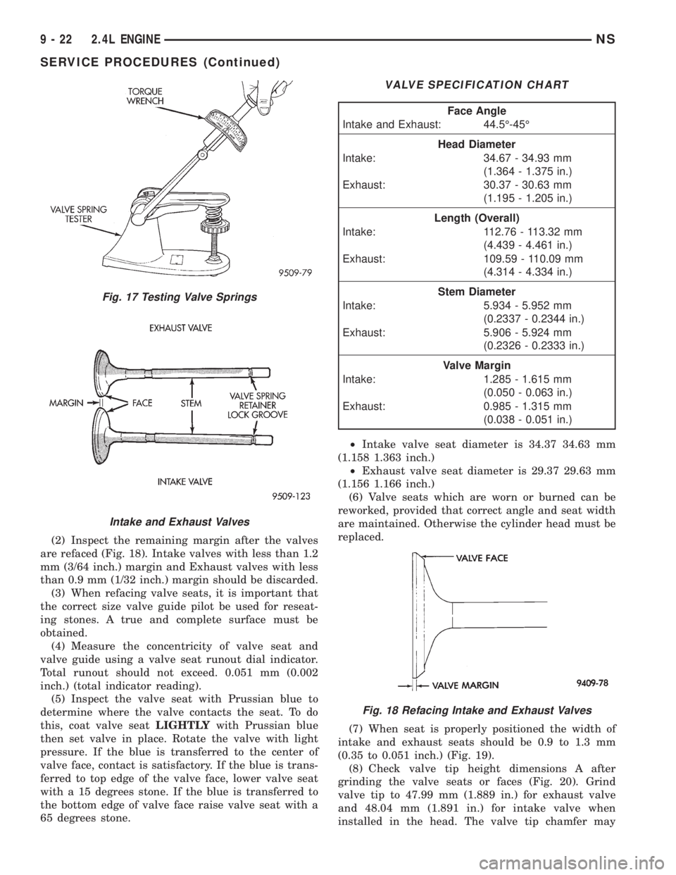
(2) Inspect the remaining margin after the valves
are refaced (Fig. 18). Intake valves with less than 1.2
mm (3/64 inch.) margin and Exhaust valves with less
than 0.9 mm (1/32 inch.) margin should be discarded.
(3) When refacing valve seats, it is important that
the correct size valve guide pilot be used for reseat-
ing stones. A true and complete surface must be
obtained.
(4) Measure the concentricity of valve seat and
valve guide using a valve seat runout dial indicator.
Total runout should not exceed. 0.051 mm (0.002
inch.) (total indicator reading).
(5) Inspect the valve seat with Prussian blue to
determine where the valve contacts the seat. To do
this, coat valve seatLIGHTLYwith Prussian blue
then set valve in place. Rotate the valve with light
pressure. If the blue is transferred to the center of
valve face, contact is satisfactory. If the blue is trans-
ferred to top edge of the valve face, lower valve seat
with a 15 degrees stone. If the blue is transferred to
the bottom edge of valve face raise valve seat with a
65 degrees stone.²Intake valve seat diameter is 34.37 34.63 mm
(1.158 1.363 inch.)
²Exhaust valve seat diameter is 29.37 29.63 mm
(1.156 1.166 inch.)
(6) Valve seats which are worn or burned can be
reworked, provided that correct angle and seat width
are maintained. Otherwise the cylinder head must be
replaced.
(7) When seat is properly positioned the width of
intake and exhaust seats should be 0.9 to 1.3 mm
(0.35 to 0.051 inch.) (Fig. 19).
(8) Check valve tip height dimensions A after
grinding the valve seats or faces (Fig. 20). Grind
valve tip to 47.99 mm (1.889 in.) for exhaust valve
and 48.04 mm (1.891 in.) for intake valve when
installed in the head. The valve tip chamfer may
Fig. 17 Testing Valve Springs
Intake and Exhaust Valves
VALVE SPECIFICATION CHART
Face Angle
Intake and Exhaust: 44.5É-45É
Head Diameter
Intake: 34.67 - 34.93 mm
(1.364 - 1.375 in.)
Exhaust: 30.37 - 30.63 mm
(1.195 - 1.205 in.)
Length (Overall)
Intake: 112.76 - 113.32 mm
(4.439 - 4.461 in.)
Exhaust: 109.59 - 110.09 mm
(4.314 - 4.334 in.)
Stem Diameter
Intake: 5.934 - 5.952 mm
(0.2337 - 0.2344 in.)
Exhaust: 5.906 - 5.924 mm
(0.2326 - 0.2333 in.)
Valve Margin
Intake: 1.285 - 1.615 mm
(0.050 - 0.063 in.)
Exhaust: 0.985 - 1.315 mm
(0.038 - 0.051 in.)
Fig. 18 Refacing Intake and Exhaust Valves
9 - 22 2.4L ENGINENS
SERVICE PROCEDURES (Continued)
Page 1105 of 1938
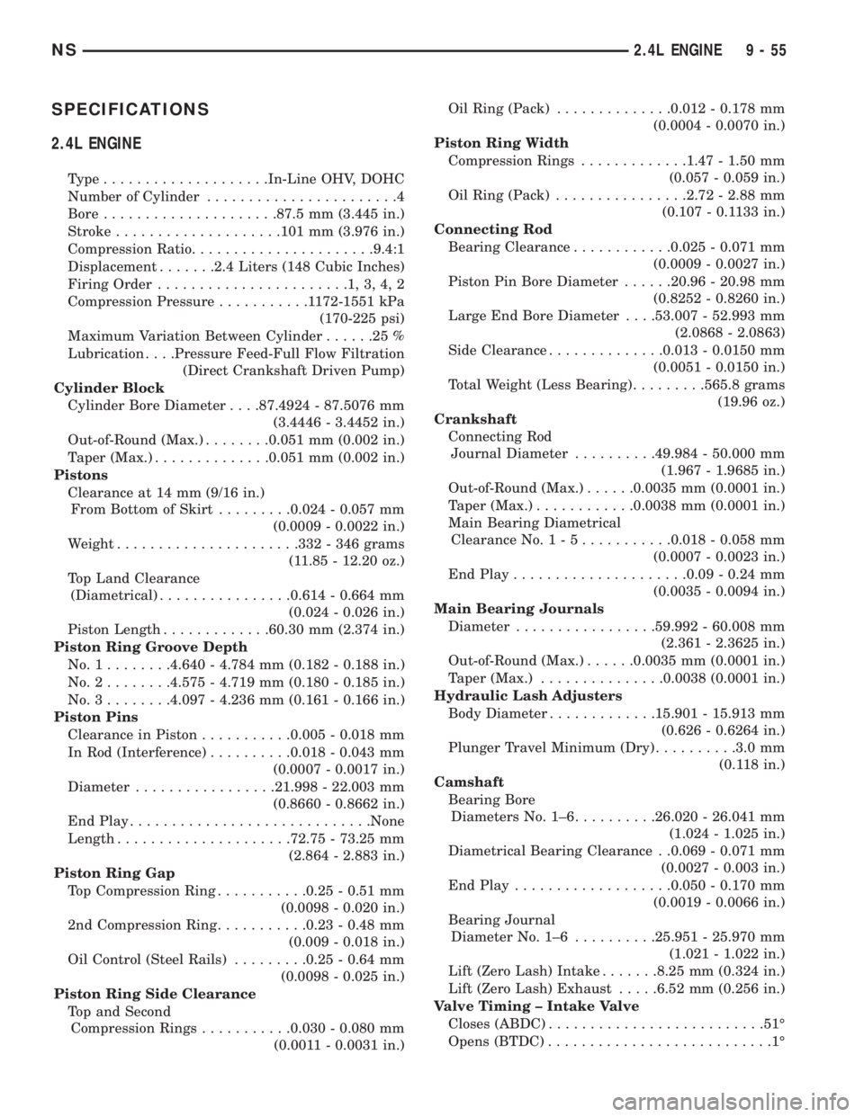
SPECIFICATIONS
2.4L ENGINE
Type....................In-Line OHV, DOHC
Number of Cylinder.......................4
Bore.....................87.5 mm (3.445 in.)
Stroke....................101 mm (3.976 in.)
Compression Ratio......................9.4:1
Displacement.......2.4 Liters (148 Cubic Inches)
Firing Order.......................1,3,4,2
Compression Pressure...........1172-1551 kPa
(170-225 psi)
Maximum Variation Between Cylinder......25%
Lubrication. . . .Pressure Feed-Full Flow Filtration
(Direct Crankshaft Driven Pump)
Cylinder Block
Cylinder Bore Diameter. . . .87.4924 - 87.5076 mm
(3.4446 - 3.4452 in.)
Out-of-Round (Max.)........0.051 mm (0.002 in.)
Taper (Max.)..............0.051 mm (0.002 in.)
Pistons
Clearance at 14 mm (9/16 in.)
From Bottom of Skirt.........0.024 - 0.057 mm
(0.0009 - 0.0022 in.)
Weight......................332 - 346 grams
(11.85 - 12.20 oz.)
Top Land Clearance
(Diametrical)................0.614 - 0.664 mm
(0.024 - 0.026 in.)
Piston Length.............60.30 mm (2.374 in.)
Piston Ring Groove Depth
No.1........4.640 - 4.784 mm (0.182 - 0.188 in.)
No.2........4.575 - 4.719 mm (0.180 - 0.185 in.)
No.3........4.097 - 4.236 mm (0.161 - 0.166 in.)
Piston Pins
Clearance in Piston...........0.005 - 0.018 mm
In Rod (Interference)..........0.018 - 0.043 mm
(0.0007 - 0.0017 in.)
Diameter.................21.998 - 22.003 mm
(0.8660 - 0.8662 in.)
End Play.............................None
Length.....................72.75 - 73.25 mm
(2.864 - 2.883 in.)
Piston Ring Gap
Top Compression Ring...........0.25 - 0.51 mm
(0.0098 - 0.020 in.)
2nd Compression Ring...........0.23 - 0.48 mm
(0.009 - 0.018 in.)
Oil Control (Steel Rails).........0.25 - 0.64 mm
(0.0098 - 0.025 in.)
Piston Ring Side Clearance
Top and Second
Compression Rings...........0.030 - 0.080 mm
(0.0011 - 0.0031 in.)Oil Ring (Pack)..............0.012 - 0.178 mm
(0.0004 - 0.0070 in.)
Piston Ring Width
Compression Rings.............1.47 - 1.50 mm
(0.057 - 0.059 in.)
Oil Ring (Pack)................2.72 - 2.88 mm
(0.107 - 0.1133 in.)
Connecting Rod
Bearing Clearance............0.025 - 0.071 mm
(0.0009 - 0.0027 in.)
Piston Pin Bore Diameter......20.96 - 20.98 mm
(0.8252 - 0.8260 in.)
Large End Bore Diameter. . . .53.007 - 52.993 mm
(2.0868 - 2.0863)
Side Clearance..............0.013 - 0.0150 mm
(0.0051 - 0.0150 in.)
Total Weight (Less Bearing).........565.8 grams
(19.96 oz.)
Crankshaft
Connecting Rod
Journal Diameter..........49.984 - 50.000 mm
(1.967 - 1.9685 in.)
Out-of-Round (Max.)......0.0035 mm (0.0001 in.)
Taper (Max.)............0.0038 mm (0.0001 in.)
Main Bearing Diametrical
Clearance No.1-5...........0.018 - 0.058 mm
(0.0007 - 0.0023 in.)
End Play.....................0.09 - 0.24 mm
(0.0035 - 0.0094 in.)
Main Bearing Journals
Diameter.................59.992 - 60.008 mm
(2.361 - 2.3625 in.)
Out-of-Round (Max.)......0.0035 mm (0.0001 in.)
Taper (Max.)...............0.0038 (0.0001 in.)
Hydraulic Lash Adjusters
Body Diameter.............15.901 - 15.913 mm
(0.626 - 0.6264 in.)
Plunger Travel Minimum (Dry)..........3.0 mm
(0.118 in.)
Camshaft
Bearing Bore
Diameters No. 1±6..........26.020 - 26.041 mm
(1.024 - 1.025 in.)
Diametrical Bearing Clearance . .0.069 - 0.071 mm
(0.0027 - 0.003 in.)
End Play...................0.050 - 0.170 mm
(0.0019 - 0.0066 in.)
Bearing Journal
Diameter No. 1±6..........25.951 - 25.970 mm
(1.021 - 1.022 in.)
Lift (Zero Lash) Intake.......8.25 mm (0.324 in.)
Lift (Zero Lash) Exhaust.....6.52 mm (0.256 in.)
Valve Timing ± Intake Valve
Closes (ABDC)..........................51É
Opens (BTDC)...........................1É
NS2.4L ENGINE 9 - 55
Page 1106 of 1938
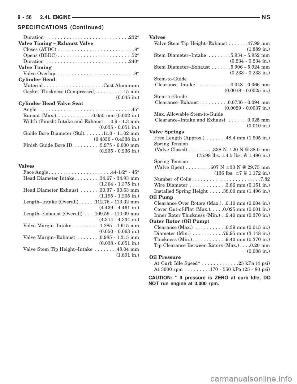
Duration.............................232É
Valve Timing ± Exhaust Valve
Closes (ATDC)...........................8É
Opens (BBDC)..........................52É
Duration.............................240É
Valve Timing
Valve Overlap...........................9É
Cylinder Head
Material.....................Cast Aluminum
Gasket Thickness (Compressed)........1.15 mm
(0.045 in.)
Cylinder Head Valve Seat
Angle.................................45É
Runout (Max.).............0.050 mm (0.002 in.)
Width (Finish) Intake and Exhaust. . .0.9 - 1.3 mm
(0.035 - 0.051 in.)
Guide Bore Diameter (Std).......11.0-11.02 mm
(0.4330 - 0.4338 in.)
Finish Guide Bore ID..........5.975 - 6.000 mm
(0.235 - 0.236 in.)
Valves
Face Angle......................44-1/2É - 45É
Head Diameter Intake.........34.67 - 34.93 mm
(1.364 - 1.375 in.)
Head Diameter Exhaust.......30.37 - 30.63 mm
(1.195 - 1.205 in.)
Length±Intake (Overall)......112.76 - 113.32 mm
(4.439 - 4.461 in.)
Length±Exhaust (Overall). . . .109.59 - 110.09 mm
(4.314 - 4.334 in.)
Valve Margin±Intake..........1.285 - 1.615 mm
(0.050 - 0.063 in.)
Valve Margin±Exhaust........0.985 - 1.315 mm
(0.038 - 0.051 in.)
Valve Stem Tip Height±Intake........48.04 mm
(1.891 in.)Valves
Valve Stem Tip Height±Exhaust.......47.99 mm
(1.889 in.)
Stem Diameter±Intake........5.934 - 5.952 mm
(0.234 - 0.234 in.)
Stem Diameter±Exhaust.......5.906 - 5.924 mm
(0.233 - 0.233 in.)
Stem-to-Guide
Clearance±Intake............0.048 - 0.066 mm
(0.0018 - 0.0025 in.)
Stem-to-Guide
Clearance±Exhaust..........0.0736 - 0.094 mm
(0.0029 - 0.0037 in.)
Max. Allowable Stem-to-Guide
Clearance±Intake and Exhaust.......0.025 mm
(0.010 in.)
Valve Springs
Free Length (Approx.).......48.4 mm (1.905 in.)
Spring Tension
(Valve Closed).........338 N620 N @ 38.0 mm
(75.98 lbs.64.5 lbs. @ 1.496 in.)
Spring Tension
(Valve Open).........607 N630 N @ 29.75 mm
(136 lbs.67 @ 1.172 in.)
Number of Coils........................7.82
Wire Diameter.............3.86 mm (0.151 in.)
Installed Spring Height.....38.00 mm (1.496 in.)
Oil Pump
Clearance Over Rotors (Max.). .0.10 mm (0.004 in.)
Cover Out-of-Flat (Max.).....0.025 mm (0.001 in.)
Inner Rotor Thickness (Min.) . .9.40 mm (0.370 in.)
Outer Rotor (Oil Pump)
Clearance (Max.)...........0.39 mm (0.015 in.)
Diameter (Min.)...........79.95 mm (3.148 in.)
Thickness (Min.)............9.40 mm (0.370 in.)
Tip Clearance Between Rotors (Max.). . . .0.20 mm
(0.008 in.)
Oil Pressure
At Curb Idle Speed*.............25kPa(4psi)
At 3000 rpm.........170 - 550 kPa (25 - 80 psi)
CAUTION: * If pressure is ZERO at curb Idle, DO
NOT run engine at 3,000 rpm.
9 - 56 2.4L ENGINENS
SPECIFICATIONS (Continued)
Page 1113 of 1938
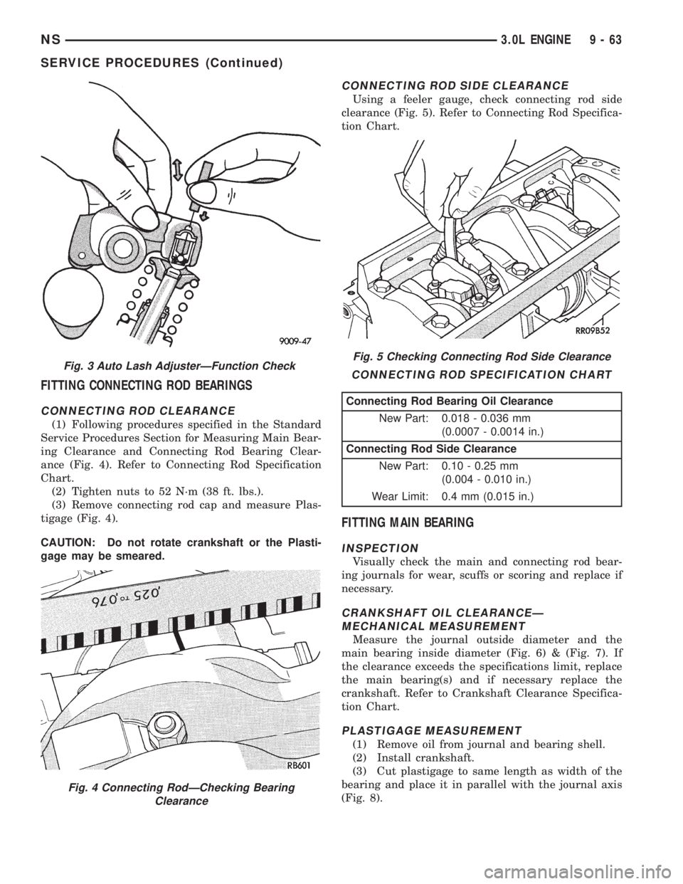
FITTING CONNECTING ROD BEARINGS
CONNECTING ROD CLEARANCE
(1) Following procedures specified in the Standard
Service Procedures Section for Measuring Main Bear-
ing Clearance and Connecting Rod Bearing Clear-
ance (Fig. 4). Refer to Connecting Rod Specification
Chart.
(2) Tighten nuts to 52 N´m (38 ft. lbs.).
(3) Remove connecting rod cap and measure Plas-
tigage (Fig. 4).
CAUTION: Do not rotate crankshaft or the Plasti-
gage may be smeared.
CONNECTING ROD SIDE CLEARANCE
Using a feeler gauge, check connecting rod side
clearance (Fig. 5). Refer to Connecting Rod Specifica-
tion Chart.
FITTING MAIN BEARING
INSPECTION
Visually check the main and connecting rod bear-
ing journals for wear, scuffs or scoring and replace if
necessary.
CRANKSHAFT OIL CLEARANCEÐ
MECHANICAL MEASUREMENT
Measure the journal outside diameter and the
main bearing inside diameter (Fig. 6) & (Fig. 7). If
the clearance exceeds the specifications limit, replace
the main bearing(s) and if necessary replace the
crankshaft. Refer to Crankshaft Clearance Specifica-
tion Chart.
PLASTIGAGE MEASUREMENT
(1) Remove oil from journal and bearing shell.
(2) Install crankshaft.
(3) Cut plastigage to same length as width of the
bearing and place it in parallel with the journal axis
(Fig. 8).
Fig. 3 Auto Lash AdjusterÐFunction Check
Fig. 4 Connecting RodÐChecking Bearing
Clearance
Fig. 5 Checking Connecting Rod Side Clearance
CONNECTING ROD SPECIFICATION CHART
Connecting Rod Bearing Oil Clearance
New Part: 0.018 - 0.036 mm
(0.0007 - 0.0014 in.)
Connecting Rod Side Clearance
New Part: 0.10 - 0.25 mm
(0.004 - 0.010 in.)
Wear Limit: 0.4 mm (0.015 in.)
NS3.0L ENGINE 9 - 63
SERVICE PROCEDURES (Continued)