1996 CHRYSLER VOYAGER width
[x] Cancel search: widthPage 1114 of 1938
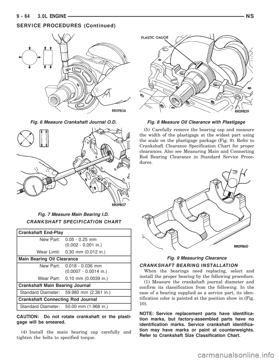
CAUTION: Do not rotate crankshaft or the plasti-
gage will be smeared.
(4) Install the main bearing cap carefully and
tighten the bolts to specified torque.(5) Carefully remove the bearing cap and measure
the width of the plastigage at the widest part using
the scale on the plastigage package (Fig. 9). Refer to
Crankshaft Clearance Specification Chart for proper
clearances. Also see Measuring Main and Connecting
Rod Bearing Clearance in Standard Service Proce-
dures.
CRANKSHAFT BEARING INSTALLATION
When the bearings need replacing, select and
install the proper bearing by the following procedure.
(1) Measure the crankshaft journal diameter and
confirm its classification from the following. In the
case of a bearing supplied as a service part, its iden-
tification color is painted at the position show in (Fig.
10).
NOTE: Service replacement parts have identifica-
tion marks, but factory-assembled parts have no
identification marks. Service crankshaft identifica-
tion may have marks or paint at counterweights.
Refer to Crankshaft Size Classification Chart.
Fig. 6 Measure Crankshaft Journal O.D.
Fig. 7 Measure Main Bearing I.D.
CRANKSHAFT SPECIFICATION CHART
Crankshaft End-Play
New Part: 0.05 - 0.25 mm
(0.002 - 0.001 in.)
Wear Limit: 0.30 mm (0.012 in.)
Main Bearing Oil Clearance
New Part: 0.018 - 0.036 mm
(0.0007 - 0.0014 in.)
Wear Part: 0.10 mm (0.0039 in.)
Crankshaft Main Bearing Journal
Standard Diameter: 59.980 mm (2.361 in.)
Crankshaft Connecting Rod Journal
Standard Diameter: 50.00 mm (1.968 in.)
Fig. 8 Measure Oil Clearance with Plastigage
Fig. 9 Measuring Clearance
9 - 64 3.0L ENGINENS
SERVICE PROCEDURES (Continued)
Page 1139 of 1938
SPECIFICATIONS
3.0L ENGINE
Type.........................60É V-6 SOHC
Number of Cylinders.......................6
Bore.....................91.1 mm (3.587 in.)
Stroke.....................76mm(2.992 in.)
Compression Ratio.....................8.85:1
Displacement..............3.0L (181 Cubic in.)
Firing Order....................1±2±3±4±5±6
Basic Ignition Timing.........Refer to Emission
Control Information Label on Vehicle
Compression Pressure...............1227 kPa
(178 psi) @ 250 RPM
Maximum Variation Between Cylinders......25%
Valve Timing
Intake Valve±Open.................19É BTDC
Intake Valve±Closed................59É ABDC
Exhaust Valve±Open................59É BBDC
Exhaust Valve±Closed...............19É ATDC
Cylinder Block
Cylinder Bore Diameter......91.1 mm (3.587 in.)
Top Surface Flatness........0.05 mm (0.002 in.)
Service Limit.............0.1 mm (0.0039 in.)
Grinding Limit of Top Surface*..........0.2 mm
(0.008 in.)
*Includes/Combined with cylinder Head Grinding
Pistons
Piston Diameter.................91.06 - 91.09
Piston to Cylinder Clearance......0.03 - 0.05 mm
(0.0012 - 0.002 in.)
Piston Ring End Gap No. 1......0.30 - 0.45 mm
(0.012 - 0.018 in.)
Service Limit..............0.8 mm (0.031 in.)
Piston Ring End Gap No. 2......0.45 - 0.60 mm
(0.018 - 0.024 in.)
Service Limit..............0.8 mm (0.031 in.)
Piston Ring End Gap Oil Control . .0.20 - 0.60 mm
(0.008 - 0.024 in.)
Service Limit..............1.0 mm (0.039 in.)
Ring Side Clearance No. 1......0.030 - 0.090 mm
(0.002 - 0.0035 in.)
Service Limit..............1.0 mm (0.039 in.)
Ring Side Clearance No. 2......0.040 - 0.085 mm
(0.0016 - 0.0033 in.)
Service Limit..............1.0 mm (0.039 in.)
Oversize Service Pistons.........0.25 - 0.50 mm
(0.010 - 0.020 in.),
0.75 - 1.00 mm (0.030 - 0.039 in.)
Connecting Rods
Bearing Clearance............0.018 - 0.036 mm
(0.0007 - 0.0014 in.)
Side Clearance................0.10 - 0.25 mm
(0.004 - 0.010 in.)Wear Limit.................0.4 mm (0.015 in.)
Length±Center to Center.......140.9 - 141.0 mm
(5.547 - 5.551 in.)
Parallelism±Twist..........0.05 mm (0.0019 in.)
Torsion...................0.1 mm (0.0039 in.)
Crankshaft
Main Journal Diameter.......59.980 - 60.0 mm
(2.361 - 2.362 in.)
Connecting Rod
Journal Diameter..........49.980 - 50.000 mm
(1.968 - 1.969 in.)
Out-of-Round (Max.).........0.03 mm (0.001 in.)
Taper (Max.).............0.005 mm (0.0002 in.)
Main and Rod
Bearing Clearance...........0.018 - 0.036 mm
(0.0007 - 0.0014 in.)
Undersize Service
Bearings................0.25 - 0.50 - 0.75 mm
(0.010 - 0.020 - 0.030 in.)
End Play.......0.05 - 0.25 mm (0.002 - 0.010 in.)
Service Limit..............0.3 mm (0.012 in.)
Cylinder Head
Flatness of Gasket Surface. . . .0.05 mm (0.002 in.)
Grinding Limit of
Gasket Surface.............0.2 mm (0.008 in.)
Cylinder Head Valve Seat
Angle±Intake and Exhaust..........44É - 44É.3'
Contact Width...................0.9 - 1.3 mm
(0.035 - 0.051 in.)
Sinkage±Service Limit........0.2 mm (0.078 in.)
Guide Bore Diameter (Std).......7.95 - 7.98 mm
(0.313 - 0.314 in.)
Valves
Face Angle......................45É - 45É 30'
Head Diameter Intake.........48.64 - 48.90 mm
(1.915 - 1.925 in.)
Head Diameter Exhaust.......40.01 - 40.26 mm
(1.575 - 1.585 in.)
Length Intake (Overall).....103.0 mm (4.055 in.)
Length Exhaust (Overall). . . .102.7 mm (4.043 in.)
Valve Margin±Intake.........1.2 mm (0.047 in.)
Service Limit..............0.7 mm (0.027 in.)
Valve Margin±Exhaust........2.0 mm (0.079 in.)
Service Limit..............1.5 mm (0.059 in.)
Valve Stem Tip Height......49.02 mm (1.929 in.)
Stem Diameter±Intake........7.960 - 7.975 mm
(0.313 - 0.314 in.)
Stem Diameter±Exhaust.......7.930 - 7.950 mm
(0.312 - 0.3125 in.)
Stem-to-Guide Clearance±Intake . . .0.03 - 0.06 mm
(0.001 - 0.002 in.)
Service Limit.............0.10 mm (0.004 in.)
Stem-to-Guide Clearance±
Exhaust.....................0.05 - 0.09 mm
(0.0019 - 0.003 in.)
NS3.0L ENGINE 9 - 89
Page 1149 of 1938
PLASTIGAGE (OIL CLEARANCE)
MEASUREMENT
(1) Remove oil from journal and bearing shell.
(2) Install crankshaft.
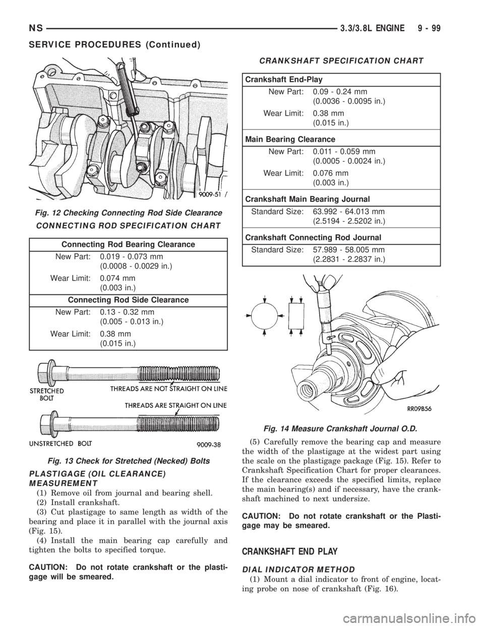
(3) Cut plastigage to same length as width of the
bearing and place it in parallel with the journal axis
(Fig. 15).
(4) Install the main bearing cap carefully and
tighten the bolts to specified torque.
CAUTION: Do not rotate crankshaft or the plasti-
gage will be smeared.(5) Carefully remove the bearing cap and measure
the width of the plastigage at the widest part using
the scale on the plastigage package (Fig. 15). Refer to
Crankshaft Specification Chart for proper clearances.
If the clearance exceeds the specified limits, replace
the main bearing(s) and if necessary, have the crank-
shaft machined to next undersize.
CAUTION: Do not rotate crankshaft or the Plasti-
gage may be smeared.
CRANKSHAFT END PLAY
DIAL INDICATOR METHOD
(1) Mount a dial indicator to front of engine, locat-
ing probe on nose of crankshaft (Fig. 16).
Fig. 12 Checking Connecting Rod Side Clearance
CONNECTING ROD SPECIFICATION CHART
Connecting Rod Bearing Clearance
New Part: 0.019 - 0.073 mm
(0.0008 - 0.0029 in.)
Wear Limit: 0.074 mm
(0.003 in.)
Connecting Rod Side Clearance
New Part: 0.13 - 0.32 mm
(0.005 - 0.013 in.)
Wear Limit: 0.38 mm
(0.015 in.)
Fig. 13 Check for Stretched (Necked) Bolts
CRANKSHAFT SPECIFICATION CHART
Crankshaft End-Play
New Part: 0.09 - 0.24 mm
(0.0036 - 0.0095 in.)
Wear Limit: 0.38 mm
(0.015 in.)
Main Bearing Clearance
New Part: 0.011 - 0.059 mm
(0.0005 - 0.0024 in.)
Wear Limit: 0.076 mm
(0.003 in.)
Crankshaft Main Bearing Journal
Standard Size: 63.992 - 64.013 mm
(2.5194 - 2.5202 in.)
Crankshaft Connecting Rod Journal
Standard Size: 57.989 - 58.005 mm
(2.2831 - 2.2837 in.)
Fig. 14 Measure Crankshaft Journal O.D.
NS3.3/3.8L ENGINE 9 - 99
SERVICE PROCEDURES (Continued)
Page 1152 of 1938
NOTE: Valve seats which are worn or burned can
be reworked, provided that correct angle and seat
width are maintained. Otherwise cylinder head must
be replaced.
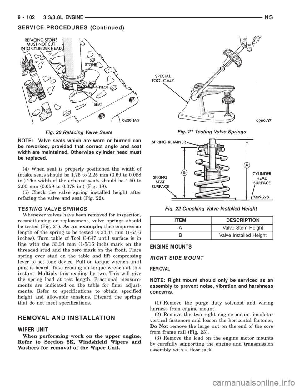
(4) When seat is properly positioned the width of
intake seats should be 1.75 to 2.25 mm (0.69 to 0.088
in.) The width of the exhaust seats should be 1.50 to
2.00 mm (0.059 to 0.078 in.) (Fig. 19).
(5) Check the valve spring installed height after
refacing the valve and seat (Fig. 22).
TESTING VALVE SPRINGS
Whenever valves have been removed for inspection,
reconditioning or replacement, valve springs should
be tested (Fig. 21).As an example;the compression
length of the spring to be tested is 33.34 mm (1-5/16
inches). Turn table of Tool C-647 until surface is in
line with the 33.34 mm (1-5/16 inch) mark on the
threaded stud and the zero mark on the front. Place
spring over stud on the table and lift compressing
lever to set tone device. Pull on torque wrench until
ping is heard. Take reading on torque wrench at this
instant. Multiply this reading by two. This will give
the spring load at test length. Fractional measure-
ments are indicated on the table for finer adjust-
ments. Refer to specifications to obtain specified
height and allowable tensions. Discard the springs
that do not meet specifications.
REMOVAL AND INSTALLATION
WIPER UNIT
When performing work on the upper engine.
Refer to Section 8K, Windshield Wipers and
Washers for removal of the Wiper Unit.
ENGINE MOUNTS
RIGHT SIDE MOUNT
REMOVAL
NOTE: Right mount should only be serviced as an
assembly to prevent noise, vibration and harshness
concerns.
(1) Remove the purge duty solenoid and wiring
harness from engine mount.
(2) Remove the two right engine mount insulator
vertical fasteners and loosen the horizontal fastener,
Do Notremove the large nut on the end of the core
from frame rail (Fig. 23).
(3) Remove the load on the engine motor mounts
by carefully supporting the engine and transmission
assembly with a floor jack.
Fig. 20 Refacing Valve SeatsFig. 21 Testing Valve Springs
Fig. 22 Checking Valve Installed Height
ITEM DESCRIPTION
A Valve Stem Height
B Valve Installed Height
9 - 102 3.3/3.8L ENGINENS
SERVICE PROCEDURES (Continued)
Page 1174 of 1938
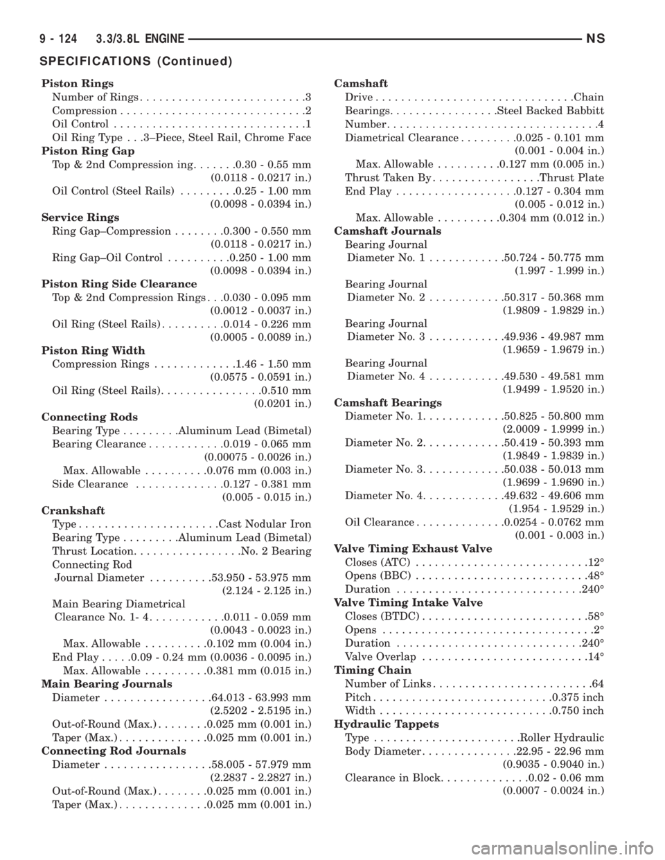
Piston Rings
Number of Rings..........................3
Compression.............................2
Oil Control..............................1
Oil Ring Type . . .3±Piece, Steel Rail, Chrome Face
Piston Ring Gap
Top & 2nd Compression ing.......0.30 - 0.55 mm
(0.0118 - 0.0217 in.)
Oil Control (Steel Rails).........0.25 - 1.00 mm
(0.0098 - 0.0394 in.)
Service Rings
Ring Gap±Compression........0.300 - 0.550 mm
(0.0118 - 0.0217 in.)
Ring Gap±Oil Control..........0.250 - 1.00 mm
(0.0098 - 0.0394 in.)
Piston Ring Side Clearance
Top & 2nd Compression Rings . . .0.030 - 0.095 mm
(0.0012 - 0.0037 in.)
Oil Ring (Steel Rails)..........0.014 - 0.226 mm
(0.0005 - 0.0089 in.)
Piston Ring Width
Compression Rings.............1.46 - 1.50 mm
(0.0575 - 0.0591 in.)
Oil Ring (Steel Rails)................0.510 mm
(0.0201 in.)
Connecting Rods
Bearing Type.........Aluminum Lead (Bimetal)
Bearing Clearance............0.019 - 0.065 mm
(0.00075 - 0.0026 in.)
Max. Allowable..........0.076 mm (0.003 in.)
Side Clearance..............0.127 - 0.381 mm
(0.005 - 0.015 in.)
Crankshaft
Type......................Cast Nodular Iron
Bearing Type.........Aluminum Lead (Bimetal)
Thrust Location.................No. 2 Bearing
Connecting Rod
Journal Diameter..........53.950 - 53.975 mm
(2.124 - 2.125 in.)
Main Bearing Diametrical
Clearance No. 1- 4............0.011 - 0.059 mm
(0.0043 - 0.0023 in.)
Max. Allowable..........0.102 mm (0.004 in.)
End Play.....0.09 - 0.24 mm (0.0036 - 0.0095 in.)
Max. Allowable..........0.381 mm (0.015 in.)
Main Bearing Journals
Diameter.................64.013 - 63.993 mm
(2.5202 - 2.5195 in.)
Out-of-Round (Max.)........0.025 mm (0.001 in.)
Taper (Max.)..............0.025 mm (0.001 in.)
Connecting Rod Journals
Diameter.................58.005 - 57.979 mm
(2.2837 - 2.2827 in.)
Out-of-Round (Max.)........0.025 mm (0.001 in.)
Taper (Max.)..............0.025 mm (0.001 in.)Camshaft
Drive...............................Chain
Bearings.................Steel Backed Babbitt
Number.................................4
Diametrical Clearance.........0.025 - 0.101 mm
(0.001 - 0.004 in.)
Max. Allowable..........0.127 mm (0.005 in.)
Thrust Taken By.................Thrust Plate
End Play...................0.127 - 0.304 mm
(0.005 - 0.012 in.)
Max. Allowable..........0.304 mm (0.012 in.)
Camshaft Journals
Bearing Journal
Diameter No. 1............50.724 - 50.775 mm
(1.997 - 1.999 in.)
Bearing Journal
Diameter No. 2............50.317 - 50.368 mm
(1.9809 - 1.9829 in.)
Bearing Journal
Diameter No. 3............49.936 - 49.987 mm
(1.9659 - 1.9679 in.)
Bearing Journal
Diameter No. 4............49.530 - 49.581 mm
(1.9499 - 1.9520 in.)
Camshaft Bearings
Diameter No. 1.............50.825 - 50.800 mm
(2.0009 - 1.9999 in.)
Diameter No. 2.............50.419 - 50.393 mm
(1.9849 - 1.9839 in.)
Diameter No. 3.............50.038 - 50.013 mm
(1.9699 - 1.9690 in.)
Diameter No. 4.............49.632 - 49.606 mm
(1.954 - 1.9529 in.)
Oil Clearance..............0.0254 - 0.0762 mm
(0.001 - 0.003 in.)
Valve Timing Exhaust Valve
Closes (ATC)...........................12É
Opens (BBC)...........................48É
Duration.............................240É
Valve Timing Intake Valve
Closes (BTDC)..........................58É
Opens.................................2É
Duration.............................240É
Valve Overlap..........................14É
Timing Chain
Number of Links.........................64
Pitch............................0.375 inch
Width...........................0.750 inch
Hydraulic Tappets
Type .......................Roller Hydraulic
Body Diameter...............22.95 - 22.96 mm
(0.9035 - 0.9040 in.)
Clearance in Block..............0.02 - 0.06 mm
(0.0007 - 0.0024 in.)
9 - 124 3.3/3.8L ENGINENS
SPECIFICATIONS (Continued)
Page 1175 of 1938
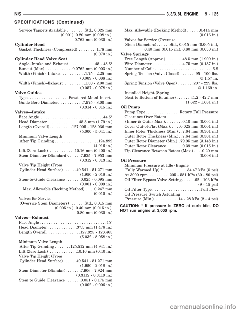
Service Tappets Available........Std., 0.025 mm
(0.001), 0.20 mm (0.008 in.),
0.762 mm (0.030 in.)
Cylinder Head
Gasket Thickness (Compressed)........1.78 mm
(0.070 in.)
Cylinder Head Valve Seat
Angle±Intake and Exhaust...........45-45.5É
Runout (Max)............0.0762 mm (0.003 in.)
Width (Finish)±Intake...........1.75 - 2.25 mm
(0.069 - 0.088 in.)
Width (Finish)±Exhaust.........1.50 - 2.00 mm
(0.057 - 0.078 in.)
Valve Guides
Type..................Powdered Metal Inserts
Guide Bore Diameter...........7.975 - 8.00 mm
(0.314 - 0.315 in.)
ValvesÐIntake
Face Angle...........................44.5É
Head Diameter..............45.5 mm (1.79 in.)
Length (Overall)..........127.005 - 128.036 mm
(5.000 - 5.041 in.)
Minimum Valve Length
After Tip Grinding...................124.892
(4.916 in.)
Lift (Zero Lash)...........10.16 mm (0.400 in.)
Stem Diameter (Standard)......7.935 - 7.953 mm
(0.312 - 0.313 in.)
Valve Tip Height (From
Cylinder Head Surface)......49.541 - 51.271 mm
(1.950 - 2.018 in.)
Stem-to-Guide Clearance.......0.025 - 0.095 mm
(0.001 - 0.003 in.)
Max. Allowable (Rocking Method). . . .0.247 mm
(0.010 in.)
Valves for Service
(Oversize Stem Diameters).......Std., 0.015 mm
(0.005 in.), 0.40 mm (0.015 in.),
0.80 mm (0.030 in.)
ValvesÐExhaust
Face Angle.............................45É
Head Diameter.............37.5 mm (1.476 in.)
Length Overall..............127.825 - 128.465
(5.032 - 5.058 in.)
Minimum Valve Length
After Tip Grinding.......125.512 mm (4.941 in.)
Lift (Zero Lash)............10.16 mm (0.40 in.)
Valve Tip Height (From
Cylinder Head Surface)......49.541 - 51.271 mm
(1.950 - 2.018 in.)
Stem Diameter (Standar).......7.906 - 7.924 mm
(0.3112 - 0.3119 in.)
Stem to Guide Clearance.......0.051 - 0.175 mm
(0.002 - 0.006 in.)Max. Allowable (Rocking Method)......0.414 mm
(0.016 in.)
Valves for Service (Oversize
Stem Diameters)......Std., 0.015 mm (0.005 in.),
0.40 mm (0.015 in.), 0.80 mm (0.030 in.)
Valve Springs
Free Length (Approx.).......48.5 mm (1.909 in.)
Wire Diameter.............4.75 mm (0.187 in.)
Number of Coils.........................6.8
Spring Tension (Valve Closed).......95-100lbs.
@ 1.57 in.
Spring Tension (Valve Open).......207 - 229 lbs.
@ 1.169 in.
Installed Height (Spring
Seat to Bottom of Retainer)......41.2 - 42.7 mm
(1.622 - 1.681 in.)
Oil Pump
Pump Type...............Rotary Full Pressure
Clearance Over Rotors
(Inner & Outer Max.)........0.10 mm (0.004 in.)
Cover Out-of-Flat (Max.).....0.025 mm (0.001 in.)
Inner Rotor Thickness (Min.) . .7.64 mm (0.301 in.)
Outer Rotor Thickness (Min.) . .7.64 mm (0.301 in.)
Outer Rotor Diameter (Min.) .79.95 mm (3.148 in.)
Outer Rotor Clearance.......0.39 mm (0.015 in.)
Tip Clearance Between Rotors (Max.). . . .0.20 mm
(0.008 in.)
Oil Pressure
Minimum Pressure at Idle (Engine
Fully Warmed Up)*...........34.47 kPa (5 psi)
At 3000 rpm.........205 - 551 kPa (30 - 80 psi)
Oil Filter Bypass Valve Setting......62-103kPa
(9 - 15 psi)
Oil Filter Type.....................Full Flow
Oil Pressure Switch Actuating
Pressure (Min.)...........14-28kPa(2 - 4 psi)
CAUTION: * If pressure is ZERO at curb Idle, DO
NOT run engine at 3,000 rpm.
NS3.3/3.8L ENGINE 9 - 125
SPECIFICATIONS (Continued)
Page 1209 of 1938
Total runout should not exceed. 0.051 mm (0.002
inch.) (total indicator reading).
(5) Inspect the valve seat with Prussian blue to
determine where the valve contacts the seat. To do
this, coat valve seatLIGHTLYwith Prussian blue
then set valve in place. Rotate the valve with light
pressure. If the blue is transferred to the center of
valve face, contact is satisfactory. If the blue is trans-
ferred to top edge of the valve face, lower valve seat
with a 15 degrees stone. If the blue is transferred to
the bottom edge of valve face raise valve seat with a
65 degrees stone.
²Intake valve seat diameter is 33 mm (1.299 in.)
²Exhaust valve seat diameter is 28 mm (1.102
in.)
(6) Valve seats which are worn or burned can be
reworked, provided that correct angle and seat width
are maintained. The intake valve seat must be ser-
viced when the valve seat width is 2.0 mm (0.079 in.)
or greater. The exhaust valve seat must be serviced
when the valve seat width is 2.5 mm (0.098 in.) or
greater. Otherwise the cylinder head must be
replaced.
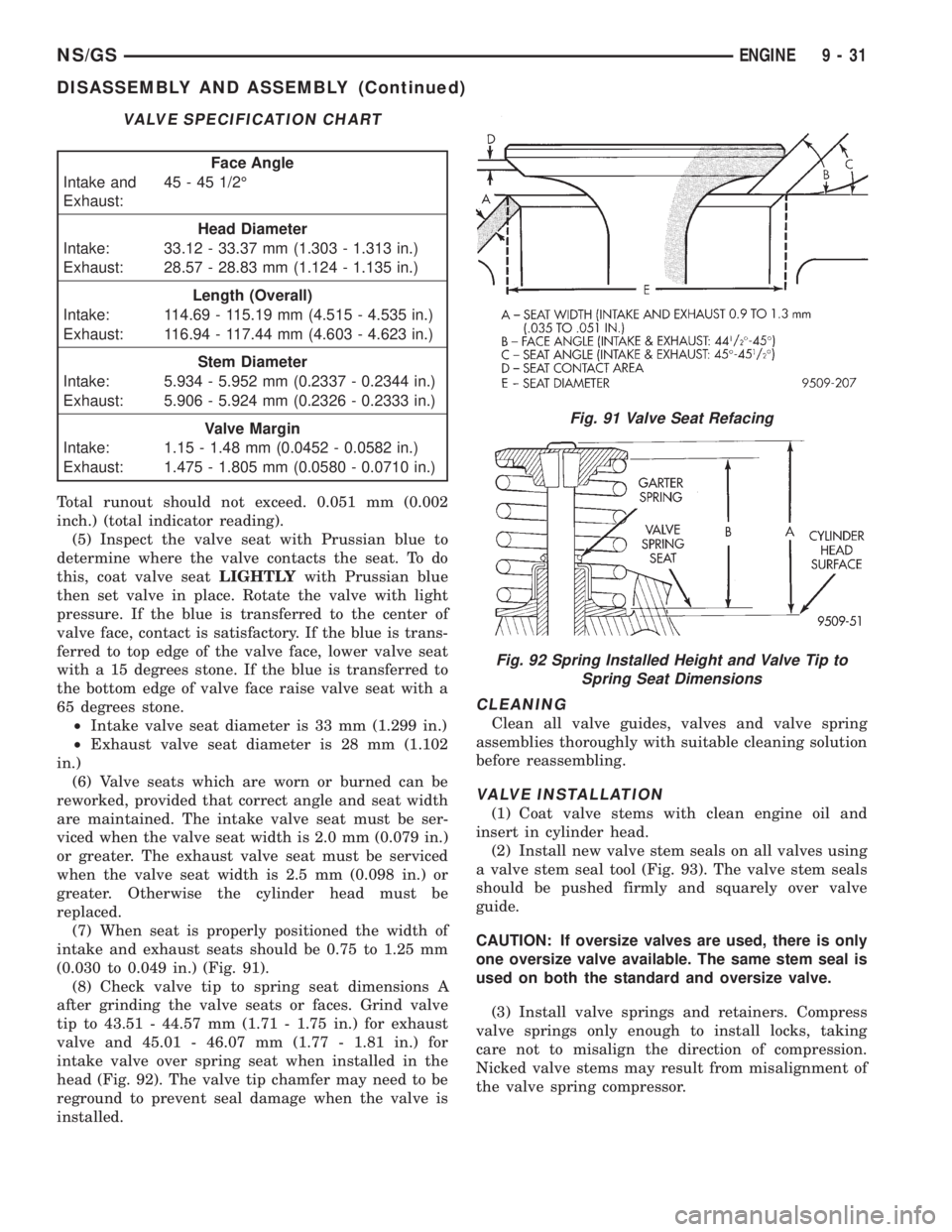
(7) When seat is properly positioned the width of
intake and exhaust seats should be 0.75 to 1.25 mm
(0.030 to 0.049 in.) (Fig. 91).
(8) Check valve tip to spring seat dimensions A
after grinding the valve seats or faces. Grind valve
tip to 43.51 - 44.57 mm (1.71 - 1.75 in.) for exhaust
valve and 45.01 - 46.07 mm (1.77 - 1.81 in.) for
intake valve over spring seat when installed in the
head (Fig. 92). The valve tip chamfer may need to be
reground to prevent seal damage when the valve is
installed.
CLEANING
Clean all valve guides, valves and valve spring
assemblies thoroughly with suitable cleaning solution
before reassembling.
VALVE INSTALLATION
(1) Coat valve stems with clean engine oil and
insert in cylinder head.
(2) Install new valve stem seals on all valves using
a valve stem seal tool (Fig. 93). The valve stem seals
should be pushed firmly and squarely over valve
guide.
CAUTION: If oversize valves are used, there is only
one oversize valve available. The same stem seal is
used on both the standard and oversize valve.
(3) Install valve springs and retainers. Compress
valve springs only enough to install locks, taking
care not to misalign the direction of compression.
Nicked valve stems may result from misalignment of
the valve spring compressor.
VALVE SPECIFICATION CHART
Face Angle
Intake and
Exhaust:45 - 45 1/2É
Head Diameter
Intake: 33.12 - 33.37 mm (1.303 - 1.313 in.)
Exhaust: 28.57 - 28.83 mm (1.124 - 1.135 in.)
Length (Overall)
Intake: 114.69 - 115.19 mm (4.515 - 4.535 in.)
Exhaust: 116.94 - 117.44 mm (4.603 - 4.623 in.)
Stem Diameter
Intake: 5.934 - 5.952 mm (0.2337 - 0.2344 in.)
Exhaust: 5.906 - 5.924 mm (0.2326 - 0.2333 in.)
Valve Margin
Intake: 1.15 - 1.48 mm (0.0452 - 0.0582 in.)
Exhaust: 1.475 - 1.805 mm (0.0580 - 0.0710 in.)
Fig. 91 Valve Seat Refacing
Fig. 92 Spring Installed Height and Valve Tip to
Spring Seat Dimensions
NS/GSENGINE 9 - 31
DISASSEMBLY AND ASSEMBLY (Continued)
Page 1213 of 1938
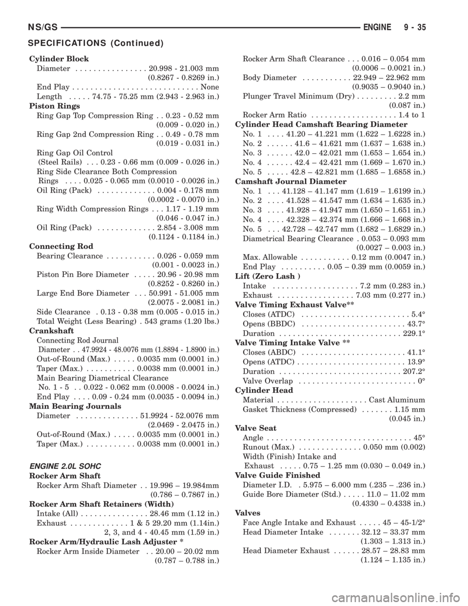
Cylinder Block
Diameter................20.998 - 21.003 mm
(0.8267 - 0.8269 in.)
End Play............................None
Length.....74.75 - 75.25 mm (2.943 - 2.963 in.)
Piston Rings
Ring Gap Top Compression Ring . . 0.23 - 0.52 mm
(0.009 - 0.020 in.)
Ring Gap 2nd Compression Ring . . 0.49 - 0.78 mm
(0.019 - 0.031 in.)
Ring Gap Oil Control
(Steel Rails) . . . 0.23 - 0.66 mm (0.009 - 0.026 in.)
Ring Side Clearance Both Compression
Rings....0.025 - 0.065 mm (0.0010 - 0.0026 in.)
Oil Ring (Pack).............0.004 - 0.178 mm
(0.0002 - 0.0070 in.)
Ring Width Compression Rings . . . 1.17 - 1.19 mm
(0.046 - 0.047 in.)
Oil Ring (Pack).............2.854 - 3.008 mm
(0.1124 - 0.1184 in.)
Connecting Rod
Bearing Clearance...........0.026 - 0.059 mm
(0.001 - 0.0023 in.)
Piston Pin Bore Diameter.....20.96 - 20.98 mm
(0.8252 - 0.8260 in.)
Large End Bore Diameter . . . 50.991 - 51.005 mm
(2.0075 - 2.0081 in.)
Side Clearance . 0.13 - 0.38 mm (0.005 - 0.015 in.)
Total Weight (Less Bearing) . 543 grams (1.20 lbs.)
Crankshaft
Connecting Rod Journal
Diameter . .
47.9924 - 48.0076 mm (1.8894 - 1.8900 in.)
Out-of-Round (Max.).....0.0035 mm (0.0001 in.)
Taper (Max.)...........0.0038 mm (0.0001 in.)
Main Bearing Diametrical Clearance
No.1-5 ..0.022 - 0.062 mm (0.0008 - 0.0024 in.)
End Play....0.09 - 0.24 mm (0.0035 - 0.0094 in.)
Main Bearing Journals
Diameter..............51.9924 - 52.0076 mm
(2.0469 - 2.0475 in.)
Out-of-Round (Max.).....0.0035 mm (0.0001 in.)
Taper (Max.)...........0.0038 mm (0.0001 in.)
ENGINE 2.0L SOHC
Rocker Arm Shaft
Rocker Arm Shaft Diameter . . 19.996 ± 19.984mm
(0.786 ± 0.7867 in.)
Rocker Arm Shaft Retainers (Width)
Intake (All)...............28.46 mm (1.12 in.)
Exhaust.............1&529.20 mm (1.14in.)
2, 3, and 4 - 40.45 mm (1.59 in.)
Rocker Arm/Hydraulic Lash Adjuster *
Rocker Arm Inside Diameter . . 20.00 ± 20.02 mm
(0.787 ± 0.788 in.)Rocker Arm Shaft Clearance . . . 0.016 ± 0.054 mm
(0.0006 ± 0.0021 in.)
Body Diameter...........22.949 ± 22.962 mm
(0.9035 ± 0.9040 in.)
Plunger Travel Minimum (Dry).........2.2mm
(0.087 in.)
Rocker Arm Ratio...................1.4to1
Cylinder Head Camshaft Bearing Diameter
No.1 ....41.20 ± 41.221 mm (1.622 ± 1.6228 in.)
No.2 ......41.6 ± 41.621 mm (1.637 ± 1.638 in.)
No.3 ......42.0 ± 42.021 mm (1.653 ± 1.654 in.)
No.4 ......42.4 ± 42.421 mm (1.669 ± 1.670 in.)
No.5 .....42.8 ± 42.821 mm (1.685 ± 1.6858 in.)
Camshaft Journal Diameter
No. 1 . . . 41.128 ± 41.147 mm (1.619 ± 1.6199 in.)
No.2 ....41.528 ± 41.547 mm (1.634 ± 1.635 in.)
No.3 ....41.928 ± 41.947 mm (1.650 ± 1.651 in.)
No.4 ....42.328 ± 42.374 mm (1.666 ± 1.668 in.)
No. 5 . . . 42.728 ± 42.747 mm (1.682 ± 1.6829 in.)
Diametrical Bearing Clearance . 0.053 ± 0.093 mm
(0.0027 ± 0.003 in.)
Max. Allowable...........0.12 mm (0.0047 in.)
End Play..........0.05 ± 0.39 mm (0.0059 in.)
Lift (Zero Lash )
Intake...................7.2mm(0.283 in.)
Exhaust.................7.03 mm (0.277 in.)
Valve Timing Exhaust Valve**
Closes (ATDC)........................5.4É
Opens (BBDC).......................43.7É
Duration...........................229.1É
Valve Timing Intake Valve **
Closes (ABDC).......................41.1É
Opens (ATDC)........................13.9É
Duration...........................207.2É
Valve Overlap..........................0É
Cylinder Head
Material....................Cast Aluminum
Gasket Thickness (Compressed).......1.15 mm
(0.045 in.)
Valve Seat
Angle................................45É
Runout (Max.)..............0.050 mm (0.002)
Width (Finish) Intake and
Exhaust.....0.75 ± 1.25 mm (0.030 ± 0.049 in.)
Valve Guide Finished
Diameter I.D. . 5.975 ± 6.000 mm (.235 ± .236 in.)
Guide Bore Diameter (Std.).....11.0±11.02 mm
(0.4330 ± 0.4338 in.)
Valves
Face Angle Intake and Exhaust.....45±45-1/2É
Head Diameter Intake.......32.12 ± 33.37 mm
(1.303 ± 1.313 in.)
Head Diameter Exhaust......28.57 ± 28.83 mm
(1.124 ± 1.135 in.)
NS/GSENGINE 9 - 35
SPECIFICATIONS (Continued)