1996 CHRYSLER VOYAGER width
[x] Cancel search: widthPage 1337 of 1938

(brake, park/neutral, air conditioning). Deceleration
die out is also prevented by increasing airflow when
the throttle is closed quickly after a driving (speed)
condition.
DUTY CYCLE EVAP CANISTER PURGE
SOLENOIDÐPCM OUTPUT
The duty cycle EVAP purge solenoid regulates the
rate of vapor flow from the EVAP canister to the
throttle body. The PCM operates the solenoid.
During the cold start warm-up period and the hot
start time delay, the PCM does not energize the sole-
noid. When de-energized, no vapors are purged. The
PCM de-energizes the solenoid during open loop oper-
ation.
The engine enters closed loop operation after it
reaches a specified temperature and the time delay
ends. During closed loop operation, the PCM ener-
gizes and de-energizes the solenoid 5 or 10 times per
second, depending upon operating conditions. The
PCM varies the vapor flow rate by changing solenoid
pulse width. Pulse width is the amount of time the
solenoid energizes.
A rubber boot covers the duty cycle EVAP purge
solenoid. The solenoid attaches to a bracket mounted
to the right engine mount (Fig. 31). The top of the
solenoid has the word TOP on it. The solenoid will
not operate properly unless it is installed correctly.
PROPORTIONAL PURGE SOLENOID
All vehicles use a proportional purge solenoid. The
solenoid regulates the rate of vapor flow from theEVAP canister to the throttle body. The PCM oper-
ates the solenoid.
During the cold start warm-up period and the hot
start time delay, the PCM does not energize the sole-
noid. When de-energized, no vapors are purged.
The proportional purge solenoid operates at a fre-
quency of 200 hz and is controlled by an engine con-
troller circuit that senses the current being applied
to the proportional purge solenoid and then adjusts
that current to achieve the desired purge flow. The
proportional purge solenoid controls the purge rate of
fuel vapors from the vapor canister and fuel tank to
the engine intake manifold.
ELECTRONIC EGR TRANSDUCER SOLENOIDÐPCM
OUTPUT
The electronic EGR transducer contains an electri-
cally operated solenoid and a back-pressure trans-
ducer (Fig. 33) or (Fig. 34) or (Fig. 35). The PCM
operates the solenoid. The PCM determines when to
energize the solenoid. Exhaust system back-pressure
controls the transducer.
When the PCM energizes the solenoid, vacuum
does not reach the transducer. Vacuum flows to the
transducer when the PCM de-energizes the solenoid.
When exhaust system back-pressure becomes high
enough, it fully closes a bleed valve in the trans-
ducer. When the PCM de-energizes the solenoid and
back-pressure closes the transducer bleed valve, vac-
uum flows through the transducer to operate the
EGR valve.
De-energizing the solenoid, but not fully closing the
transducer bleed hole (because of low back-pressure),
varies the strength of vacuum applied to the EGR
valve. Varying the strength of the vacuum changes
the amount of EGR supplied to the engine. This pro-
Fig. 31 Duty Cycle EVAP Purge Solenoid
Fig. 32 Proportional Purge Solenoid
NSFUEL SYSTEM 14 - 43
DESCRIPTION AND OPERATION (Continued)
Page 1339 of 1938
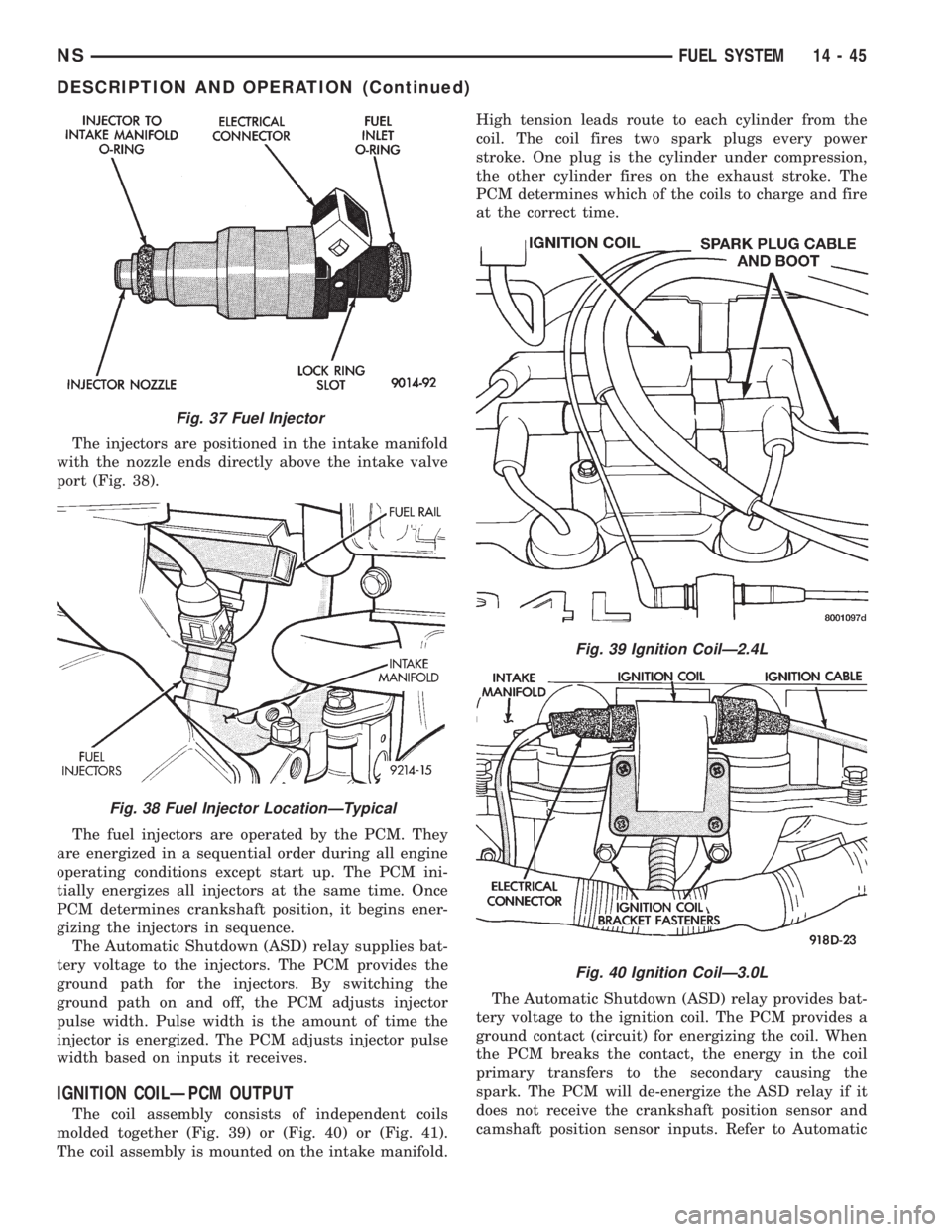
The injectors are positioned in the intake manifold
with the nozzle ends directly above the intake valve
port (Fig. 38).
The fuel injectors are operated by the PCM. They
are energized in a sequential order during all engine
operating conditions except start up. The PCM ini-
tially energizes all injectors at the same time. Once
PCM determines crankshaft position, it begins ener-
gizing the injectors in sequence.
The Automatic Shutdown (ASD) relay supplies bat-
tery voltage to the injectors. The PCM provides the
ground path for the injectors. By switching the
ground path on and off, the PCM adjusts injector
pulse width. Pulse width is the amount of time the
injector is energized. The PCM adjusts injector pulse
width based on inputs it receives.
IGNITION COILÐPCM OUTPUT
The coil assembly consists of independent coils
molded together (Fig. 39) or (Fig. 40) or (Fig. 41).
The coil assembly is mounted on the intake manifold.High tension leads route to each cylinder from the
coil. The coil fires two spark plugs every power
stroke. One plug is the cylinder under compression,
the other cylinder fires on the exhaust stroke. The
PCM determines which of the coils to charge and fire
at the correct time.
The Automatic Shutdown (ASD) relay provides bat-
tery voltage to the ignition coil. The PCM provides a
ground contact (circuit) for energizing the coil. When
the PCM breaks the contact, the energy in the coil
primary transfers to the secondary causing the
spark. The PCM will de-energize the ASD relay if it
does not receive the crankshaft position sensor and
camshaft position sensor inputs. Refer to Automatic
Fig. 37 Fuel Injector
Fig. 38 Fuel Injector LocationÐTypical
Fig. 39 Ignition CoilÐ2.4L
Fig. 40 Ignition CoilÐ3.0L
NSFUEL SYSTEM 14 - 45
DESCRIPTION AND OPERATION (Continued)
Page 1416 of 1938
The speed sensor generates 8 pulses per sensor
revolution. These signals, in conjunction with a
closed throttle signal from the throttle position sen-
sor, indicate a closed throttle deceleration to the
PCM. When the vehicle is stopped at idle, a closed
throttle signal is received by the PCM (but a speed
sensor signal is not received).
In addition to determining distance and vehicle
speed, the output from the sensor is used to control
speed control operation.
SPEED CONTROLÐPCM INPUTS
The speed control system provides five separate
inputs to the PCM; On/Off, Set, Resume/Accel, Cancel,
and Decel.. The On/Off input informs the PCM that
the speed control system has been activated. The Set
input informs the PCM that a fixed vehicle speed has
been selected. The Resume input indicates to the PCM
that the previous fixed speed is requested.
Speed control operation will start at 50 km/h±142
km/h (35±85 mph). The upper range of operation is
not restricted by vehicle speed. Inputs that affect
speed control operation are vehicle speed sensor and
throttle position sensor.
Refer to Group 8H for further speed control infor-
mation.
DIESEL PCM RELAYÐPCM INPUT
A 12 volt signal at this input indicates to the PCM
that the Diesel relay has been activated. The Diesel
relay is located in the PDC. The PDC is located next
to the battery in the engine compartment. For the
location of the relay within the PDC, refer to label on
PDC cover.
This input is used only to sense that the Diesel
relay is energized. If the PCM does not see 12 volts +
at this input when the Diesel relay should be acti-
vated, it will set a Diagnostic Trouble Code (DTC).
FIVE VOLT POWERÐPCM OUTPUT
This circuit supplies approximately 5 volts to
power the Accelerator Pedal Postion Sensor, Mass Air
Flow Sensor, and A/C Pressure Sensor.
ENGINE COOLANT GAUGEÐPCM OUTPUT
Refer to the Instrument Panel and Gauges group
for additional information.
ENGINE OIL PRESSURE GAUGEÐPCM OUTPUT
Refer to the Instrument Panel and Gauges group
for additional information.
GLOW PLUG LAMPÐPCM OUTPUT
The Glow Plug lamp (malfunction indicator lamp)
illuminates on the message center each time the igni-
tion (key) switch is turned on. It will stay on for
about two seconds as a bulb test.If the PCM receives an incorrect signal, or no sig-
nal from certain sensors or components, the lamp
BLINKS. This is a warning that the PCM has
recorded a system or sensor malfunction. It signals
an immediate need for service. There are only 5
HARD faults that can turn on this lamp to make it
blink.
SPEED CONTROLÐPCM OUTPUTS
These two circuits control the fuel quantity actua-
tor to regulate vehicle speed. Refer to Group 8H for
Speed Control information.
AIR CONDITIONING RELAYÐPCM OUTPUT
This circuit controls a ground signal for operation
of the A/C clutch relay. Also refer to Air Conditioning
(A/C) ControlsÐPCM Input for additional informa-
tion.
The A/C relay is located in the Power Distribution
Center (PDC). The PDC is located next to the battery
in the engine compartment. For the location of the
relay within the PDC, refer to label on PDC cover.
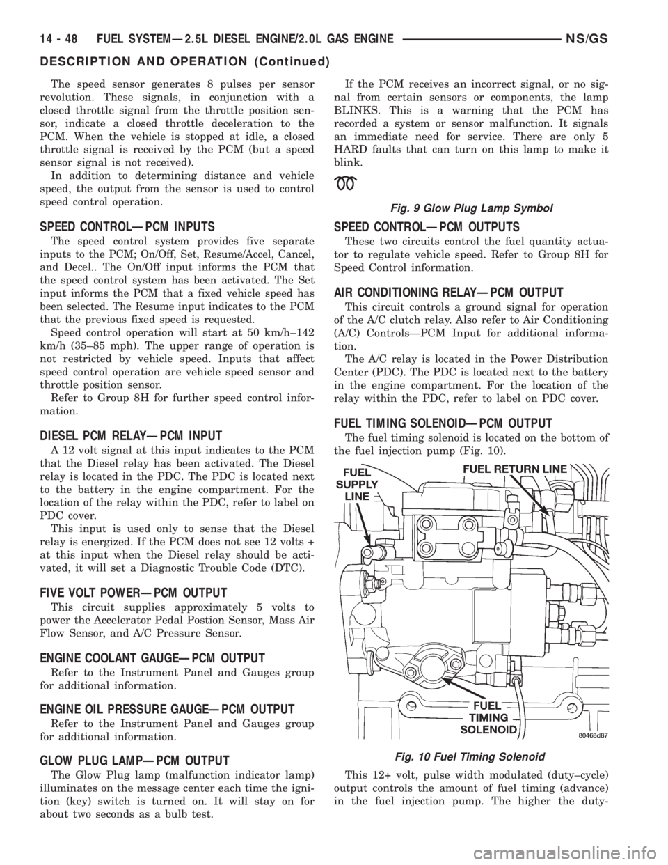
FUEL TIMING SOLENOIDÐPCM OUTPUT
The fuel timing solenoid is located on the bottom of
the fuel injection pump (Fig. 10).
This 12+ volt, pulse width modulated (duty±cycle)
output controls the amount of fuel timing (advance)
in the fuel injection pump. The higher the duty-
Fig. 9 Glow Plug Lamp Symbol
Fig. 10 Fuel Timing Solenoid
14 - 48 FUEL SYSTEMÐ2.5L DIESEL ENGINE/2.0L GAS ENGINENS/GS
DESCRIPTION AND OPERATION (Continued)
Page 1727 of 1938
WHEELS
INDEX
page page
DESCRIPTION AND OPERATION
WHEEL INFORMATION.................... 9
DIAGNOSIS AND TESTING
TIRE AND WHEEL RUNOUT............... 10
WHEEL INSPECTION...................... 9SERVICE PROCEDURES
TIRE AND WHEEL BALANCE............... 11
WHEEL INSTALLATION................... 11
SPECIFICATIONS
WHEEL SPECIFICATIONS................. 12
DESCRIPTION AND OPERATION
WHEEL INFORMATION
Original equipment wheels are designed for proper
operation at all loads up to the specified maximum
vehicle capacity.
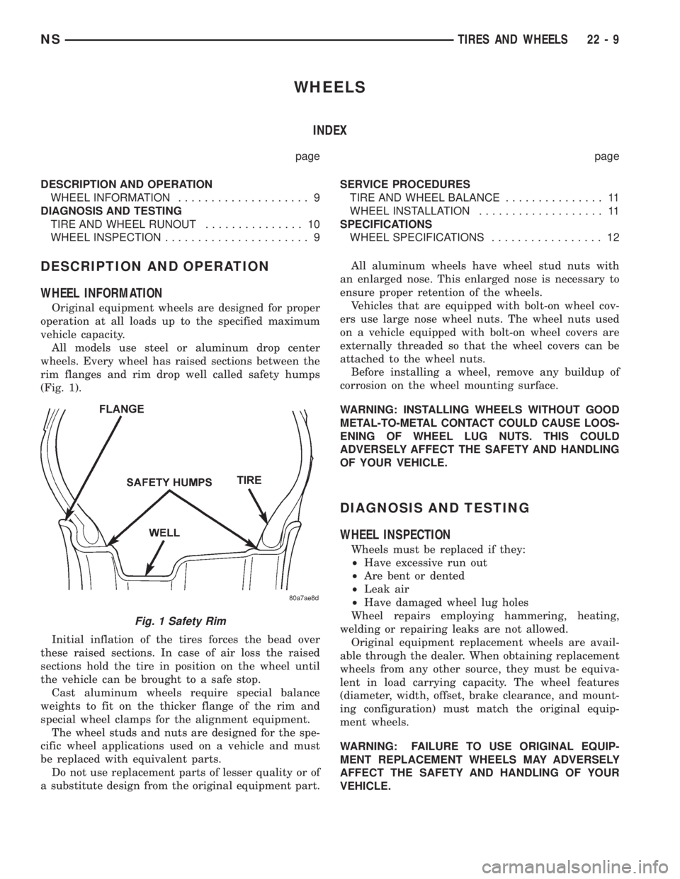
All models use steel or aluminum drop center
wheels. Every wheel has raised sections between the
rim flanges and rim drop well called safety humps
(Fig. 1).
Initial inflation of the tires forces the bead over
these raised sections. In case of air loss the raised
sections hold the tire in position on the wheel until
the vehicle can be brought to a safe stop.
Cast aluminum wheels require special balance
weights to fit on the thicker flange of the rim and
special wheel clamps for the alignment equipment.
The wheel studs and nuts are designed for the spe-
cific wheel applications used on a vehicle and must
be replaced with equivalent parts.
Do not use replacement parts of lesser quality or of
a substitute design from the original equipment part.All aluminum wheels have wheel stud nuts with
an enlarged nose. This enlarged nose is necessary to
ensure proper retention of the wheels.
Vehicles that are equipped with bolt-on wheel cov-
ers use large nose wheel nuts. The wheel nuts used
on a vehicle equipped with bolt-on wheel covers are
externally threaded so that the wheel covers can be
attached to the wheel nuts.
Before installing a wheel, remove any buildup of
corrosion on the wheel mounting surface.
WARNING: INSTALLING WHEELS WITHOUT GOOD
METAL-TO-METAL CONTACT COULD CAUSE LOOS-
ENING OF WHEEL LUG NUTS. THIS COULD
ADVERSELY AFFECT THE SAFETY AND HANDLING
OF YOUR VEHICLE.
DIAGNOSIS AND TESTING
WHEEL INSPECTION
Wheels must be replaced if they:
²Have excessive run out
²Are bent or dented
²Leak air
²Have damaged wheel lug holes
Wheel repairs employing hammering, heating,
welding or repairing leaks are not allowed.
Original equipment replacement wheels are avail-
able through the dealer. When obtaining replacement
wheels from any other source, they must be equiva-
lent in load carrying capacity. The wheel features
(diameter, width, offset, brake clearance, and mount-
ing configuration) must match the original equip-
ment wheels.
WARNING: FAILURE TO USE ORIGINAL EQUIP-
MENT REPLACEMENT WHEELS MAY ADVERSELY
AFFECT THE SAFETY AND HANDLING OF YOUR
VEHICLE.
Fig. 1 Safety Rim
NSTIRES AND WHEELS 22 - 9
Page 1907 of 1938
Adaptive Fuel Factor
Barometric Pressure
Engine Speed
Module Spark Advance
Speed Control Target
Intake Air Temp Degrees
Intake Air Temp Volts
Charging System Goal
Theft Alarm Status
Map Sensor Voltage
Vehicle Speed
Throttle Opening (percentage)
TPS Calculated
Cam Timing Position
Target Idle
Time From Start To Run
Run Time At Stall
Injector Pulse-width
Upstream O2S Volts
Downstream O2S Volts
Closed Loop Timer
Short Term Adaptive
Current Adaptive Cell
Adaptive Memory Cell 0
Adaptive Memory Cell 1
Adaptive Memory Cell 2
Adaptive Memory Cell 3
Adaptive Memory Cell 4
Adaptive Memory Cell 5
Adaptive Memory Cell 6
Adaptive Memory Cell 7
Adaptive Memory Cell 8
Adaptive Memory Cell 9
Adaptive Memory Cell 10
Adaptive Memory Cell 11
Adaptive Memory Cell 12
Adaptive Memory Cell 13
Adaptive Memory Cell 14
Adaptive Memory Cell 15
Purge Free Idle Cell
Purge Free Cell 2 (corresponds to memory cell 2)
Purge Free Cell 3 (corresponds to memory cell 5)
Target IAC Steps
Retard Cylinder (1)
Retard Cylinder (2)
Retard Cylinder (3)
Retard Cylinder (4)
Retard Cylinder (5)
Retard Cylinder (6)CIRCUIT ACTUATION TEST MODE
The Circuit Actuation Test Mode checks for proper
operation of output circuits or devices the Powertrain
Control Module (PCM) may not internally recognize.
The PCM attempts to activate these outputs and
allow an observer to verify proper operation. Most of
the tests provide an audible or visual indication of
device operation (click of relay contacts, fuel spray,
etc.). Except for intermittent conditions, if a device
functions properly during testing, assume the device,
its associated wiring, and driver circuit work cor-
rectly.
DIAGNOSTIC TROUBLE CODES
A Diagnostic Trouble Code (DTC) indicates the
PCM has recognized an abnormal condition in the
system.
The preferred and most accurate method of retriev-
ing a DTC is by using the DRB scan tool. The scan
tool supplies detailed diagnostic information which
can be used to more accurately diagnose causes for a
DTC.
Remember that DTC's are the results of a sys-
tem or circuit failure, but do not directly iden-
tify the failed component or components.
NOTE: For a list of DTC's, refer to the charts in this
section.
BULB CHECK
Each time the ignition key is turned to the ON
position, the malfunction indicator (check engine)
lamp on the instrument panel should illuminate for
approximately 2 seconds then go out. This is done for
a bulb check.
OBTAINING DTC'S USING DRB SCAN TOOL
(1) Connect the DRB scan tool to the data link
(diagnostic) connector. This connector is located in
the passenger compartment; at the lower edge of
instrument panel; near the steering column.
(2) Turn the ignition switch on and access the
ªRead Faultº screen.
(3) Record all the DTC's and ªfreeze frameº infor-
mation shown on the DRB scan tool.
(4) To erase DTC's, use the ªErase Trouble Codeº
data screen on the DRB scan tool.Do not erase any
DTC's until problems have been investigated
and repairs have been performed.
NSEMISSION CONTROL SYSTEMS 25 - 3
DESCRIPTION AND OPERATION (Continued)
Page 1912 of 1938
MONITORED SYSTEMS
There are new electronic circuit monitors that
check fuel, emission, engine and ignition perfor-
mance. These monitors use information from various
sensor circuits to indicate the overall operation of the
fuel, engine, ignition and emission systems and thus
the emissions performance of the vehicle.
The fuel, engine, ignition and emission systems
monitors do not indicate a specific component prob-
lem. They do indicate that there is an implied prob-
lem within one of the systems and that a specific
problem must be diagnosed.
If any of these monitors detect a problem affecting
vehicle emissions, the Malfunction Indicator (Check
Engine) Lamp will be illuminated. These monitors
generate Diagnostic Trouble Codes that can be dis-
played with the check engine lamp or a scan tool.
The following is a list of the system monitors:
²EGR Monitor
²Misfire Monitor
²Fuel System Monitor
²Oxygen Sensor Monitor
²Oxygen Sensor Heater Monitor
²Catalyst Monitor
²Evaporative System Leak Detection Monitor
Following is a description of each system monitor,
and its DTC.
Refer to the appropriate Powertrain Diagnos-
tics Procedures manual for diagnostic proce-
dures.
HEX 66, and 7AÐOXYGEN SENSOR (O2S)
MONITOR
Effective control of exhaust emissions is achieved
by an oxygen feedback system. The most important
element of the feedback system is the O2S. The O2S
is located in the exhaust path. Once it reaches oper-
ating temperature 300É to 350ÉC (572É to 662ÉF), the
sensor generates a voltage that is inversely propor-
tional to the amount of oxygen in the exhaust. The
information obtained by the sensor is used to calcu-
late the fuel injector pulse width. This maintains a
14.7 to 1 air fuel (A/F) ratio. At this mixture ratio,
the catalyst works best to remove hydrocarbons (HC),
carbon monoxide (CO) and nitrous oxide (NOx) from
the exhaust.
The O2S is also the main sensing element for the
EGR, Catalyst and Fuel Monitors.
The O2S may fail in any or all of the following
manners:
²Slow response rate
²Reduced output voltage
²Dynamic shift
²Shorted or open circuitsResponse rate is the time required for the sensor to
switch from lean to rich once it is exposed to a richer
than optimum A/F mixture or vice versa. As the sen-
sor starts malfunctioning, it could take longer to
detect the changes in the oxygen content of the
exhaust gas.
The output voltage of the O2S ranges from 0 to 1
volt. A good sensor can easily generate any output
voltage in this range as it is exposed to different con-
centrations of oxygen. To detect a shift in the A/F
mixture (lean or rich), the output voltage has to
change beyond a threshold value. A malfunctioning
sensor could have difficulty changing beyond the
threshold value.
HEX 67, 69, 7C, and 7DÐOXYGEN SENSOR
HEATER MONITOR
If there is an oxygen sensor (O2S) DTC as well as
a O2S heater DTC, the O2S fault MUST be repaired
first. After the O2S fault is repaired, verify that the
heater circuit is operating correctly.
Effective control of exhaust emissions is achieved
by an oxygen feedback system. The most important
element of the feedback system is the O2S. The O2S
is located in the exhaust path. Once it reaches oper-
ating temperature 300É to 350ÉC (572 Éto 662ÉF), the
sensor generates a voltage that is inversely propor-
tional to the amount of oxygen in the exhaust. The
information obtained by the sensor is used to calcu-
late the fuel injector pulse width. This maintains a
14.7 to 1 Air Fuel (A/F) ratio. At this mixture ratio,
the catalyst works best to remove hydrocarbons (HC),
carbon monoxide (CO) and nitrogen oxide (NOx) from
the exhaust.
The voltage readings taken from the O2S are very
temperature sensitive. The readings are not accurate
below 300ÉC. Heating of the O2S is done to allow the
engine controller to shift to closed loop control as
soon as possible. The heating element used to heat
the O2S must be tested to ensure that it is heating
the sensor properly.
The O2S circuit is monitored for a drop in voltage.
The sensor output is used to test the heater by iso-
lating the effect of the heater element on the O2S
output voltage from the other effects.
HEX 2EÐEGR MONITOR
The Powertrain Control Module (PCM) performs
an on-board diagnostic check of the EGR system.
The EGR system consists of two main components:
a vacuum solenoid and a vacuum operated valve with
a back pressure transducer. The EGR monitor is used
to test whether the EGR system is operating within
specifications. The diagnostic check activates only
during selected engine/driving conditions. When the
25 - 8 EMISSION CONTROL SYSTEMSNS
DESCRIPTION AND OPERATION (Continued)
Page 1913 of 1938
conditions are met, the EGR is turned off (solenoid
energized) and the O2S compensation control is mon-
itored. Turning off the EGR shifts the air fuel (A/F)
ratio in the lean direction. The O2S data should indi-
cate an increase in the O2 concentration in the com-
bustion chamber when the exhaust gases are no
longer recirculated. While this test does not directly
measure the operation of the EGR system, it can be
inferred from the shift in the O2S data whether the
EGR system is operating correctly. Because the O2S
is being used, the O2S test must pass its test before
the EGR test.
HEX 6A,6B, 6C, 6D, 6E, AE, and AFÐMISFIRE
MONITOR
Excessive engine misfire results in increased cata-
lyst temperature and causes an increase in HC emis-
sions. Severe misfires could cause catalyst damage.
To prevent catalytic convertor damage, the PCM
monitors engine misfire.
The Powertrain Control Module (PCM) monitors
for misfire during most engine operating conditions
(positive torque) by looking at changes in the crank-
shaft speed. If a misfire occurs the speed of the
crankshaft will vary more than normal.
HEX 76, 77, 78, and 79ÐFUEL SYSTEM
MONITOR
To comply with clean air regulations, vehicles are
equipped with catalytic converters. These converters
reduce the emission of hydrocarbons, oxides of nitro-
gen and carbon monoxide. The catalyst works best
when the air fuel (A/F) ratio is at or near the opti-
mum of 14.7 to 1.
The PCM is programmed to maintain the optimum
air/fuel ratio of 14.7 to 1. This is done by making
short term corrections in the fuel injector pulse width
based on the O2S output. The programmed memory
acts as a self calibration tool that the engine control-
ler uses to compensate for variations in engine spec-
ifications, sensor tolerances and engine fatigue over
the life span of the engine. By monitoring the actual
air-fuel ratio with the O2S (short term) and multiply-
ing that with the program long-term (adaptive) mem-
ory and comparing that to the limit, it can be
determined whether it will pass an emissions test. If
a malfunction occurs such that the PCM cannot
maintain the optimum A/F ratio, then the MIL will
be illuminated.
HEX 70, and B4ÐCATALYST MONITOR
To comply with clean air regulations, vehicles are
equipped with catalytic converters. These converters
reduce the emission of hydrocarbons, oxides of nitro-
gen and carbon monoxide.Normal vehicle miles or engine misfire can cause a
catalyst to decay. A meltdown of the ceramic core can
cause a reduction of the exhaust passage. This can
increase vehicle emissions and deteriorate engine
performance, driveability and fuel economy.
The catalyst monitor uses dual oxygen sensors
(O2S's) to monitor the efficiency of the converter. The
dual O2Ss strategy is based on the fact that as a cat-
alyst deteriorates, its oxygen storage capacity and its
efficiency are both reduced. By monitoring the oxy-
gen storage capacity of a catalyst, its efficiency can
be indirectly calculated. The upstream O2S is used to
detect the amount of oxygen in the exhaust gas
before the gas enters the catalytic converter. The
PCM calculates the A/F mixture from the output of
the O2S. A low voltage indicates high oxygen content
(lean mixture). A high voltage indicates a low content
of oxygen (rich mixture).
When the upstream O2S detects a lean condition,
there is an abundance of oxygen in the exhaust gas.
A functioning converter would store this oxygen so it
can use it for the oxidation of HC and CO. As the
converter absorbs the oxygen, there will be a lack of
oxygen downstream of the converter. The output of
the downstraem O2S will indicate limited activity in
this condition.
As the converter loses the ability to store oxygen,
the condition can be detected from the behavior of
the downstream O2S. When the efficiency drops, no
chemical reaction takes place. This means the con-
centration of oxygen will be the same downstream as
upstream. The output voltage of the downstream
O2S copies the voltage of the upstream sensor. The
only difference is a time lag (seen by the PCM)
between the switching of the O2S's.
To monitor the system, the number of lean-to-rich
switches of upstream and downstream O2S's is
counted. The ratio of downstream switches to
upstream switches is used to determine whether the
catalyst is operating properly. An effective catalyst
will have fewer downstream switches than it has
upstream switches i.e., a ratio closer to zero. For a
totally ineffective catalyst, this ratio will be one-to-
one, indicating that no oxidation occurs in the device.
The system must be monitored so that when cata-
lyst efficiency deteriorates and exhaust emissions
increase to over the legal limit, the MIL (check
engine lamp) will be illuminated.
HEX A0, A1, B7, and B8ÐLEAK DETECTION
PUMP MONITOR
The leak detection assembly incorporates two pri-
mary functions: it must detect a leak in the evapora-
tive system and seal the evaporative system so the
leak detection test can be run.
NSEMISSION CONTROL SYSTEMS 25 - 9
DESCRIPTION AND OPERATION (Continued)