1996 CHRYSLER VOYAGER air bleeding
[x] Cancel search: air bleedingPage 158 of 1938

MUST always be used when installing brake
hose to caliper.
(12) Bleed the brake system (see Bleeding Brake
System).
WHEEL CYLINDER REAR DRUM BRAKE
DISASSEMBLE
To disassemble the wheel cylinders, proceed as fol-
lows:
(1) Pry boots away from cylinders and remove (Fig.
193).
(2) PressINon one piston to force out opposite
piston, cup and spring (Fig. 193). Then using a soft
tool such as a dowel rod, press out the cup and piston
that remain in the wheel cylinder.
(3) Wash wheel cylinder, pistons, and spring (Fig.
193) in clean brake fluid or alcohol;(DO NOT USE
ANY PETROLEUM BASE SOLVENTS)clean thor-
oughly and blow dry with compressed air. Inspect cyl-
inder bore and piston for scoring and pitting. (Do not
use a rag as lint from the rag will stick to bore sur-
faces.)
(4) Wheel cylinder bores and pistons that are
badly scored or pitted should be replaced. Cylinder
walls that have light scratches, or show signs of cor-
rosion, can usually be cleaned with crocus cloth,
using a circular motion. Black stains on the cylinder
walls are caused by piston cups and will not impair
operation of cylinder.
ASSEMBLE
Before assembling the pistons and new cups in the
wheel cylinders, dip them in clean brake fluid. If the
boots are deteriorated, cracked or do not fit tightly on
the pistons or the cylinder casting, install new boots.
(1) Coat cylinder bore with clean brake fluid.
(2) Lightly coat the sealing lip and outer surfaces
of the wheel cylinder cups withonly Mopar Pro-
tect-A-Cup Lubricant p/n 04883068 and no sub-
stitute.
(3) Install expansion spring with cup expanders in
cylinder. Install cups in each end of cylinder with
open end of cups facing each other (Fig. 193).
(4) Install piston in each end of cylinder having
the flat face of each piston contacting the flat face of
each cup, already installed (Fig. 193).
(5) Install a boot over each end of cylinder (Fig.
193).Be careful not to damage boot during
installation.
CLEANING AND INSPECTION
FRONT DISC BRAKE PAD LINING INSPECTION
If a visual inspection does not adequately deter-
mine the condition of the lining, a physical check will
be necessary. To check the amount of lining wear,
remove the wheel and tire assemblies, and the cali-
pers.
Remove the shoe and lining assemblies. (See Brake
Shoe Removal).
Combined shoe and lining thickness should be
measured at the thinnest part of the brake shoe
assembly.
When a shoe and lining assembly is worn to a
thickness of approximately 7.95 mm (0.313 inch) it
should be replaced.
Replacebothshoe assemblies (inboard and out-
board) on the front wheels. It is also necessary that
bothfront wheel brake shoe assembly sets be
replaced, whenever shoe assemblies on either side of
the vehicle require replacement.
If a shoe assembly does not require replacement,
reinstall it, making sure each shoe assembly is
returned to its original position. (See Brake Shoe
Installation).
REAR DISC BRAKES
BRAKE PAD LINING WEAR
If a visual inspection does not adequately deter-
mine the condition of the lining, a physical check will
be necessary. To check the amount of lining wear,
remove the wheel and tire assemblies, and the cali-
pers.
Remove the rear disc brake shoes. Refer to Rear
Disc Brake Shoe Removal in the Removal And Instal-
Fig. 192 Installing Dust Boot In Caliper Counterbore
5 - 76 BRAKESNS
DISASSEMBLY AND ASSEMBLY (Continued)
Page 181 of 1938

Before test driving a brake complaint vehicle, note
whether the Red or Amber Brake Warning Lamp is
turned on. If it is the Red Brake Warning Lamp,
refer to the hydraulic system section in the brake
group of this manual. If the ABS Warning lamp
was/is on, test drive the vehicle as described below, to
verify the complaint. While the ABS Warning Lamp
is on, the ABS is not functional. The standard brake
system and the ability to stop the car may not be
affected if only the ABS Warning Lamp is on.
Discuss with the owner of the vehicle or note any
other electrical problems or conditions that may be
occurring on the vehicle. They may have an effect on
the antilock brake system's function.
(1) Turn the key to the off position and then back
to the on position. Note whether the ABS Warning
Lamp continues to stay on. If it does, refer to the
diagnostic manual covering the ITT Teves Mark 20
ABS system for the required test procedures.
(2) If the ABS Warning Lamp goes out, shift into
gear and drive the car to a speed of 20 kph (12 mph)
to complete the ABS start up cycle. If at this time the
ABS Warning Lamp goes on refer to the ITT Teves
Mark 20 Diagnostic Manual.
(3) If the ABS Warning Lamp remains OUT, drive
the vehicle a short distance. During this test drive be
sure that the vehicle achieves at least 40 mph. Brake
to at least one complete stop in an ABS cycle, and
again accelerate to 25 mph.
(4) If a functional problem with the ABS system is
determined while test driving a vehicle, refer to the
diagnostic manual covering the ITT Teves Mark 20
ABS system for the required test procedures and
proper use of the DRB diagnostic scan tool.
ABS SERVICE PRECAUTIONS
The ABS uses an electronic control module, the
CAB. This module is designed to withstand normal
current draws associated with vehicle operation.
Care must be taken to avoid overloading the CAB
circuits.In testing for open or short circuits, do
not ground or apply voltage to any of the cir-
cuits unless instructed to do so for a diagnostic
procedure.These circuits should only be tested
using a high impedance multi-meter or the DRB
tester as described in this section. Power should
never be removed or applied to any control module
with the ignition in the ON position. Before removing
or connecting battery cables, fuses, or connectors,
always turn the ignition to the OFF position.
CAUTION: Use only factory wiring harnesses. Do
not cut or splice wiring to the brake circuits. The
addition of after-market electrical equipment (car
phone, radar detector, citizen band radio, trailer
lighting, trailer brakes, ect.) on a vehicle equippedwith antilock brakes may affect the function of the
antilock brake system.
SERVICE PROCEDURES
BRAKE FLUID LEVEL INSPECTION
CAUTION: Use only Mopar brake fluid or an equiv-
alent from a tightly sealed container. Brake fluid
must conform to DOT 3 specifications. Do not use
petroleum-based fluid because seal damage in the
brake system will result.
For the specific procedure covering the inspection
of the brake fluid level and adding brake fluid to the
reservoir, refer to the Service Adjustments Section in
this group of the service manual.
BLEEDING TEVES MARK 20 HYDRAULIC SYSTEM
The base brake system must be bled anytime air is
permitted to enter the hydraulic system, due to dis-
connection of brake lines, hoses or components. The
ABS system, particularly the HCU, should only be
bled when the HCU is replaced or removed from the
vehicle, or if there is reason to believe the HCU has
ingested air. Under most circumstances that would
require brake bleeding, only the base brake system
needs to be bled.
It is important to note that excessive air in the
brake system will cause a soft or spongy feeling
brake pedal.
During bleeding operations, be sure that the brake
fluid level remains close to the FULL level in the res-
ervoir. Check the fluid level periodically during the
bleeding procedure and add DOT 3 brake fluid as
required.
The Teves Mark 20 ABS hydraulic system and the
base brake hydraulic system must be bled as two
independent braking systems. The non ABS portion
of the brake system is to be bled the same as any
non ABS system. Refer to the Service Adjustments
section in this manual for the proper bleeding proce-
dure to be used. This brake system can be either
pressure bled or manually bled.
The ABS portion of the brake system MUST be
bled separately. This bleeding procedure requires the
use of the DRB Diagnostic Tester and the bleeding
sequence procedure outlined below.
ABS BLEEDING PROCEDURE
When bleeding the ABS system, the following
bleeding sequenceMUSTbe followed to insure com-
plete and adequate bleeding. The ABS system can be
bled using a manual bleeding procedure or standard
pressure bleeding equipment.
NSBRAKES 5 - 99
DIAGNOSIS AND TESTING (Continued)
Page 182 of 1938

If the brake system is to be bled using pressurized
bleeding equipment, refer to Bleeding Brake System
in the Service Adjustments section at the beginning
of this group for proper equipment usage and proce-
dures.
(1) Assemble and install all brake system compo-
nents on the vehicle making sure all hydraulic fluid
lines are installed and properly torqued.
(2) Connect the DRB Diagnostics Tester to the
diagnostics connector. The Teves Mark 20 ABS diag-
nostic connector is located under the instrument
panel to the left of the steering column cover.
(3) Using the DRB, check to make sure the CAB
does not have any fault codes stored. If it does,
remove them using the DRB.
WARNING: WHEN BLEEDING THE BRAKE SYS-
TEM WEAR SAFETY GLASSES. A CLEAR BLEED
TUBE MUST BE ATTACHED TO THE BLEEDER
SCREWS AND SUBMERGED IN A CLEAR CON-
TAINER FILLED PART WAY WITH CLEAN BRAKE
FLUID. DIRECT THE FLOW OF BRAKE FLUID AWAY
FROM THE PAINTED SURFACES OF THE VEHICLE.
BRAKE FLUID AT HIGH PRESSURE MAY COME
OUT OF THE BLEEDER SCREWS WHEN OPENED.
(4) Bleed the base brake system using the stan-
dard pressure or manual bleeding procedure as out-
lined in the Service Adjustments section of this
service manual.
(5) Using the DRB, go to the9Bleed ABS9routine.
Apply the brake pedal firmly and initiate the9Bleed
ABS9cycle one time. Release the brake pedal.
(6) Bleed the base brake system again, as in step
Step 4 above.
(7) Repeat steps Step 5 and Step 6 above until
brake fluid flows clear and is free of any air bubbles.
Check brake fluid level in reservoir periodically to
prevent reservoir from running low on brake fluid.
(8) Test drive the vehicle to be sure brakes are
operating correctly and that brake pedal is solid.
REMOVAL AND INSTALLATION
ABS GENERAL SERVICE PRECAUTIONS
CAUTION: Review this entire section prior to per-
forming any mechanical work on a vehicle equipped
with the ITT Tevis Mark 20 ABS brake system. This
section contains information on precautions per-
taining to potential component damage, vehicle
damage and personal injury which could result
when servicing an ABS equipped vehicle.
CAUTION: Only the recommended jacking or hoist-
ing positions for this vehicle are to be used when-ever it is necessary to lift a vehicle. Failure to raise
a vehicle from the recommended locations could
result in lifting a vehicle by the hydraulic control
unit mounting bracket. Lifting a vehicle by the
hydraulic control unit mounting bracket will result
in damage to the mounting bracket and the hydrau-
lic control unit.
CAUTION: Certain components of the ABS System
are not intended to be serviced individually.
Attempting to remove or disconnect certain system
components may result in improper system opera-
tion. Only those components with approved
removal and installation procedures in this manual
should be serviced.
CAUTION: Brake fluid will damage painted sur-
faces. If brake fluid is spilled on any painted sur-
faces, wash off with water immediately.
CAUTION: When performing any service procedure
on a vehicle equipped with ABS do not apply a 12
volt power source to the ground circuit of the pump
motor in the CAB. Doing this will damage the pump
motor and will require replacement of the HCU.
The following are general cautions which should be
observed when servicing the ABS system and/or
other vehicle systems. Failure to observe these pre-
cautions may result in ABS System component dam-
age.
If welding work is to be performed on the vehicle,
using an electric arc welder, the CAB connector
should be disconnected during the welding operation.
The CAB 25 way connector connector should never
be connected or disconnected with the ignition switch
in the ON position.
Many components of the ABS System are not ser-
viceable and must be replaced as an assembly. Do not
disassemble any component which is not designed to
be serviced.
HYDRAULIC CONTROL UNIT
REMOVE
(1) Disconnect the negative (ground) cable from
the battery and isolate cable.
(2) Using a brake pedal depressor, move and lock
the brake pedal to a position past the first inch of
pedal travel.This will prevent brake fluid from
draining out of the master cylinder when the
brake tubes are removed from the HCU.
(3) Raise vehicle. Vehicle is to be raised and sup-
ported on jackstands or on a frame contact type
5 - 100 BRAKESNS
SERVICE PROCEDURES (Continued)
Page 1379 of 1938

the intake manifold. Refer to Group 11, Exhaust Sys-
tem and Intake Manifold for information.
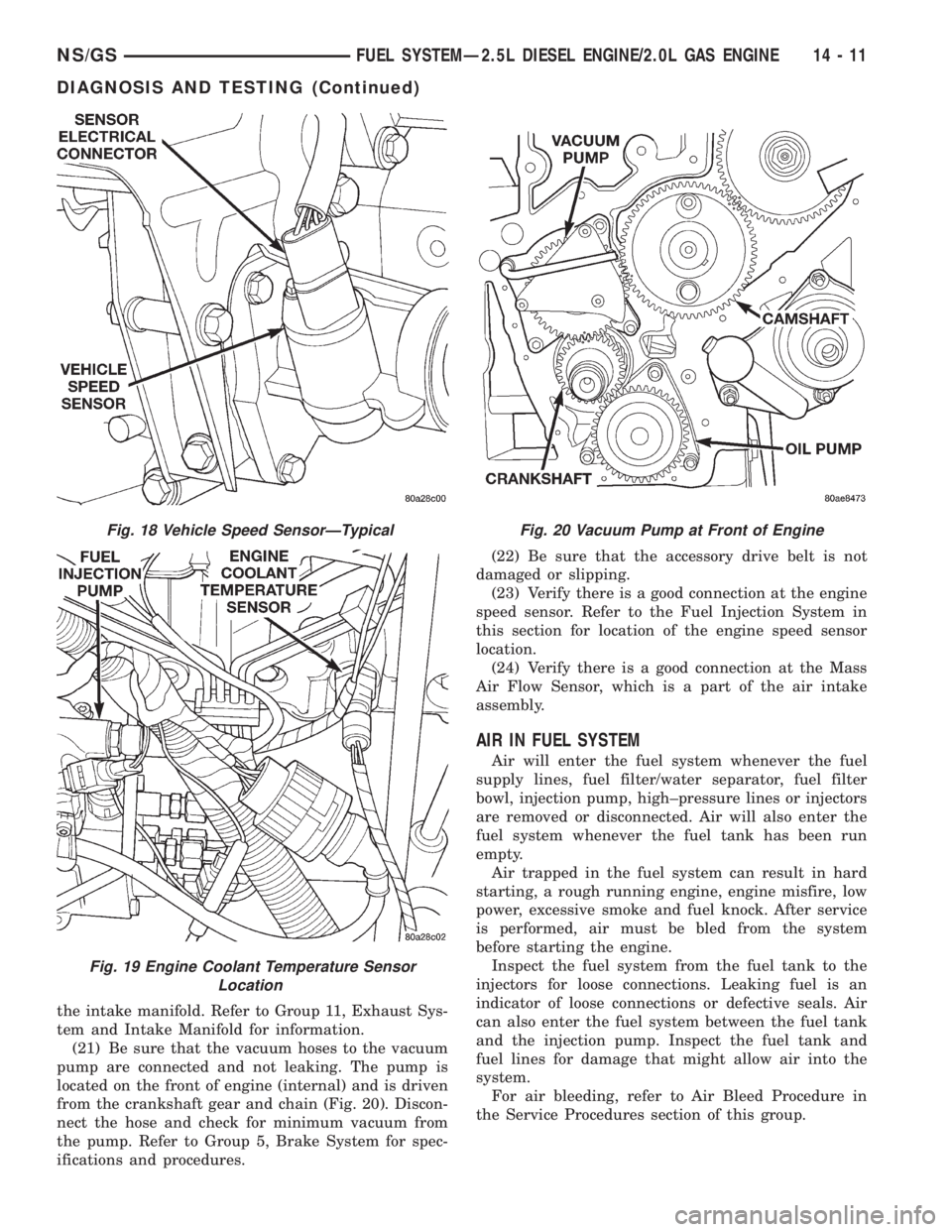
(21) Be sure that the vacuum hoses to the vacuum
pump are connected and not leaking. The pump is
located on the front of engine (internal) and is driven
from the crankshaft gear and chain (Fig. 20). Discon-
nect the hose and check for minimum vacuum from
the pump. Refer to Group 5, Brake System for spec-
ifications and procedures.(22) Be sure that the accessory drive belt is not
damaged or slipping.
(23) Verify there is a good connection at the engine
speed sensor. Refer to the Fuel Injection System in
this section for location of the engine speed sensor
location.
(24) Verify there is a good connection at the Mass
Air Flow Sensor, which is a part of the air intake
assembly.
AIR IN FUEL SYSTEM
Air will enter the fuel system whenever the fuel
supply lines, fuel filter/water separator, fuel filter
bowl, injection pump, high±pressure lines or injectors
are removed or disconnected. Air will also enter the
fuel system whenever the fuel tank has been run
empty.
Air trapped in the fuel system can result in hard
starting, a rough running engine, engine misfire, low
power, excessive smoke and fuel knock. After service
is performed, air must be bled from the system
before starting the engine.
Inspect the fuel system from the fuel tank to the
injectors for loose connections. Leaking fuel is an
indicator of loose connections or defective seals. Air
can also enter the fuel system between the fuel tank
and the injection pump. Inspect the fuel tank and
fuel lines for damage that might allow air into the
system.
For air bleeding, refer to Air Bleed Procedure in
the Service Procedures section of this group.
Fig. 18 Vehicle Speed SensorÐTypical
Fig. 19 Engine Coolant Temperature Sensor
Location
Fig. 20 Vacuum Pump at Front of Engine
NS/GSFUEL SYSTEMÐ2.5L DIESEL ENGINE/2.0L GAS ENGINE 14 - 11
DIAGNOSIS AND TESTING (Continued)
Page 1380 of 1938

FUEL HEATER RELAY TEST
The fuel heater relay is located in the Power Dis-
tribution Center (PDC). Refer to RelaysÐOperation/
Testing in Fuel Ingection System section of this
group for test procedures.
FUEL INJECTOR TEST
The fuel injection nozzels, located on the engine
cylinder head, spray fuel under high pressure into
the individual combustion chambers. Pressurized
fuel, delivered by the fuel injection pump, unseats a
spring-loaded needle valve inside the injector, and
the fuel is atomized as it escapes through the injector
opening into the engine's combustion chamber. If the
fuel injector does not operate properly, the engine
may misfire, or cause other driveability problems.
A leak in the injection pump±to±injector high±pres-
sure fuel line can cause many of the same symptoms
as a malfunctioning injector. Inspect for a leak in the
high±pressure lines before checking for a malfunc-
tioning fuel injector.
WARNING: THE INJECTION PUMP SUPPLIES HIGH-
±PRESSURE FUEL OF UP TO APPROXIMATELY
45,000 KPA (6526 PSI) TO EACH INDIVIDUAL INJEC-
TOR THROUGH THE HIGH±PRESSURE LINES. FUEL
UNDER THIS AMOUNT OF PRESSURE CAN PENE-
TRATE THE SKIN AND CAUSE PERSONAL INJURY.
WEAR SAFETY GOGGLES AND ADEQUATE PRO-
TECTIVE CLOTHING. AVOID CONTACT WITH FUEL
SPRAY WHEN BLEEDING HIGH±PRESSURE FUEL
LINES.
WARNING: DO NOT BLEED AIR FROM THE FUEL
SYSTEM OF A HOT ENGINE. DO NOT ALLOW FUEL
TO SPRAY ONTO THE EXHAUST MANIFOLD WHEN
BLEEDING AIR FROM THE FUEL SYSTEM.
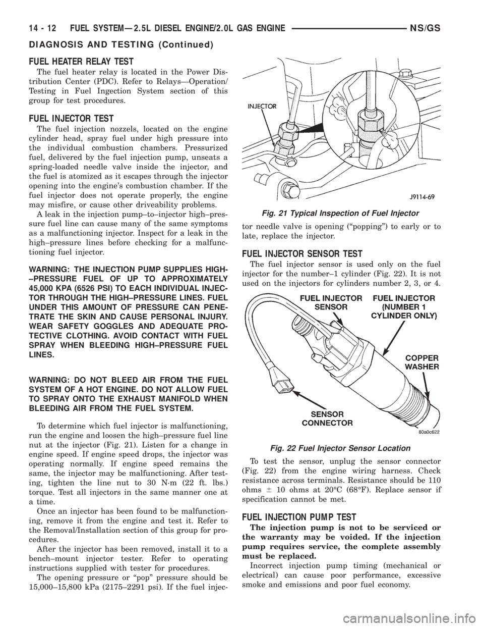
To determine which fuel injector is malfunctioning,
run the engine and loosen the high±pressure fuel line
nut at the injector (Fig. 21). Listen for a change in
engine speed. If engine speed drops, the injector was
operating normally. If engine speed remains the
same, the injector may be malfunctioning. After test-
ing, tighten the line nut to 30 N´m (22 ft. lbs.)
torque. Test all injectors in the same manner one at
a time.
Once an injector has been found to be malfunction-
ing, remove it from the engine and test it. Refer to
the Removal/Installation section of this group for pro-
cedures.
After the injector has been removed, install it to a
bench±mount injector tester. Refer to operating
instructions supplied with tester for procedures.
The opening pressure or ªpopº pressure should be
15,000±15,800 kPa (2175±2291 psi). If the fuel injec-tor needle valve is opening (ªpoppingº) to early or to
late, replace the injector.
FUEL INJECTOR SENSOR TEST
The fuel injector sensor is used only on the fuel
injector for the number±1 cylinder (Fig. 22). It is not
used on the injectors for cylinders number 2, 3, or 4.
To test the sensor, unplug the sensor connector
(Fig. 22) from the engine wiring harness. Check
resistance across terminals. Resistance should be 110
ohms610 ohms at 20ÉC (68ÉF). Replace sensor if
specification cannot be met.
FUEL INJECTION PUMP TEST
The injection pump is not to be serviced or
the warranty may be voided. If the injection
pump requires service, the complete assembly
must be replaced.
Incorrect injection pump timing (mechanical or
electrical) can cause poor performance, excessive
smoke and emissions and poor fuel economy.
Fig. 21 Typical Inspection of Fuel Injector
Fig. 22 Fuel Injector Sensor Location
14 - 12 FUEL SYSTEMÐ2.5L DIESEL ENGINE/2.0L GAS ENGINENS/GS
DIAGNOSIS AND TESTING (Continued)
Page 1382 of 1938

START positions, fuel supply is allowed at the injec-
tion pump.
(1) Disconnect the electrical pigtail connector (test
connector) (Fig. 23) from the main engine wiring har-
ness. Do not disconnect wiring directly at solenoid.
(2) Connect the leads of a voltmeter between a
good ground and the disconnected engine wiring har-
ness.
(3) Turn the key to the ON position. Do not
attempt to start engine.
(4) 12V+ should be observed at wiring harness. If
not, refer to Group 8, Wiring for wiring schematics
and repair as necessary.
(5) T
urn the key to the START position. 12V+ should
be observed at wiring harness. If not, refer to Group 8,
Wiring for wiring schematics and repair as necessary.
The fault may be in the ignition (key) switch.
12V+ must be observed in both the ON and START
positions. If 12V+ was observed, proceed to the next
step.
(6) With key still in the ON position, connect and
disconnect the wiring harness to the solenoid. As this
is done, a clicking noise should be heard coming from
the solenoid. If not, replace solenoid. Refer to Fuel
Shutdown Solenoid in the Removal/Installation sec-
tion of this group for procedures.
HIGH-PRESSURE FUEL LINE LEAK TEST
High±pressure fuel line leaks can cause starting
problems and poor engine performance.
WARNING: DUE TO EXTREME FUEL PRESSURES
OF UP TO 45,000 KPA (6526 PSI), USE EXTREME
CAUTION WHEN INSPECTING FOR HIGH±PRESSURE
FUEL LEAKS. DO NOT GET YOUR HAND, OR ANY
PART OF YOUR BODY NEAR A SUSPECTED LEAK.
INSPECT FOR HIGH±PRESSURE FUEL LEAKS WITH
A SHEET OF CARDBOARD. HIGH FUEL INJECTION
PRESSURE CAN CAUSE PERSONAL INJURY IF
CONTACT IS MADE WITH THE SKIN.
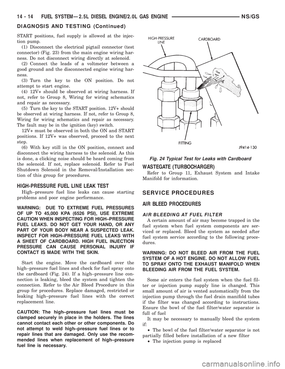
Start the engine. Move the cardboard over the
high±pressure fuel lines and check for fuel spray onto
the cardboard (Fig. 24). If a high±pressure line con-
nection is leaking, bleed the system and tighten the
connection. Refer to the Air Bleed Procedure in this
group for procedures. Replace damaged, restricted or
leaking high±pressure fuel lines with the correct
replacement line.
CAUTION: The high±pressure fuel lines must be
clamped securely in place in the holders. The lines
cannot contact each other or other components. Do
not attempt to weld high±pressure fuel lines or to
repair lines that are damaged. Only use the recom-
mended lines when replacement of high±pressure
fuel line is necessary.
WASTEGATE (TURBOCHARGER)
Refer to Group 11, Exhaust System and Intake
Manifold for information.
SERVICE PROCEDURES
AIR BLEED PROCEDURES
AIR BLEEDING AT FUEL FILTER
A certain amount of air may become trapped in the
fuel system when fuel system components are ser-
viced or replaced. Bleed the system as needed after
fuel system service according to the following proce-
dures.
WARNING: DO NOT BLEED AIR FROM THE FUEL
SYSTEM OF A HOT ENGINE. DO NOT ALLOW FUEL
TO SPRAY ONTO THE EXHAUST MANIFOLD WHEN
BLEEDING AIR FROM THE FUEL SYSTEM.
Some air enters the fuel system when the fuel fil-
ter or injection pump supply line is changed. This
small amount of air is vented automatically from the
injection pump through the fuel drain manifold tubes
if the filter was changed according to instructions.
Ensure the bowl of the fuel filter/water separator is
full of fuel
It may be necessary to manually bleed the system
if:
²The bowl of the fuel filter/water separator is not
partially filled before installation of a new filter
²The injection pump is replaced
Fig. 24 Typical Test for Leaks with Cardboard
14 - 14 FUEL SYSTEMÐ2.5L DIESEL ENGINE/2.0L GAS ENGINENS/GS
DIAGNOSIS AND TESTING (Continued)
Page 1383 of 1938

²High±pressure fuel line connections are loosened
or lines replaced
²Initial engine start±up or start±up after an
extended period of no engine operation
²Running fuel tank empty
FUEL INJECTION PUMP BLEEDING
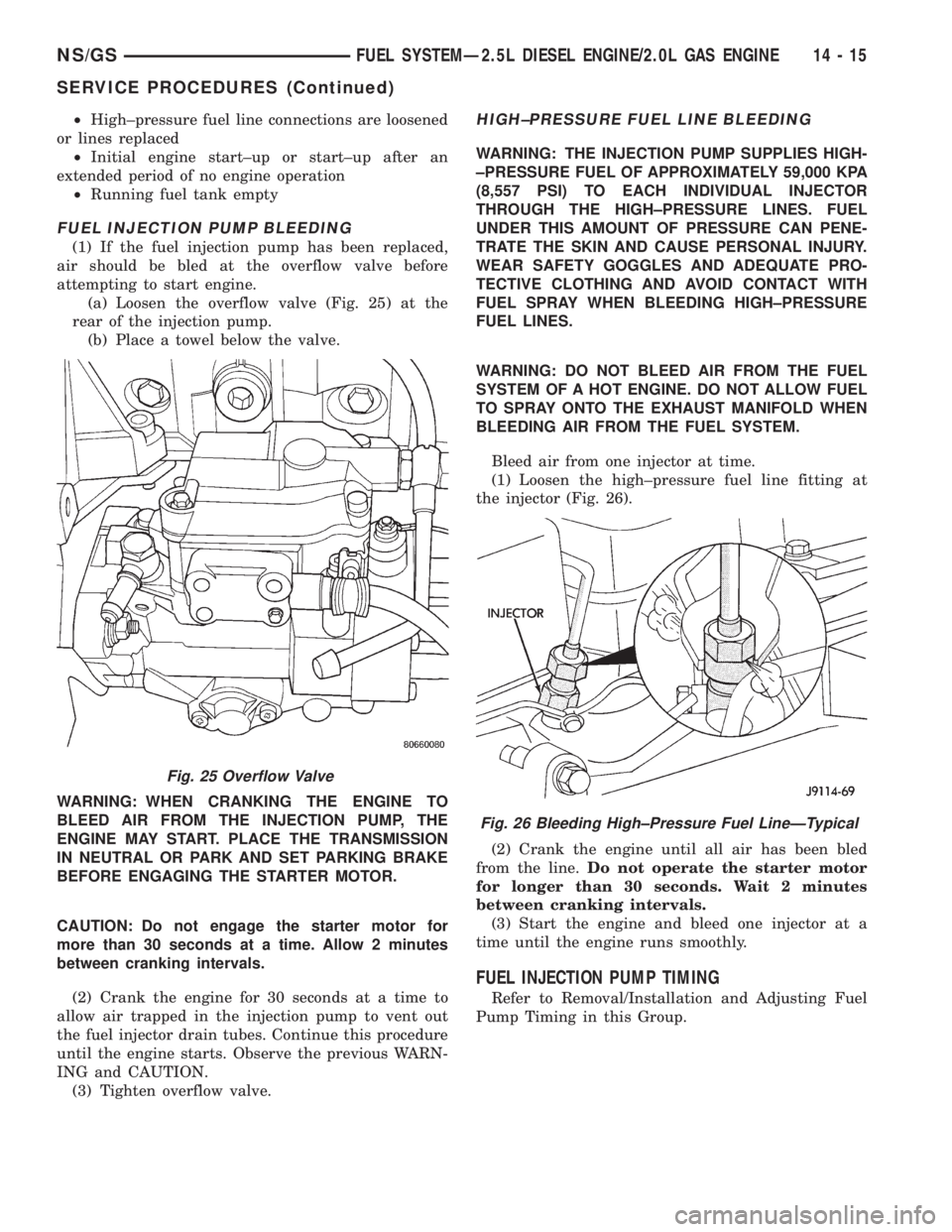
(1) If the fuel injection pump has been replaced,
air should be bled at the overflow valve before
attempting to start engine.
(a) Loosen the overflow valve (Fig. 25) at the
rear of the injection pump.
(b) Place a towel below the valve.
WARNING: WHEN CRANKING THE ENGINE TO
BLEED AIR FROM THE INJECTION PUMP, THE
ENGINE MAY START. PLACE THE TRANSMISSION
IN NEUTRAL OR PARK AND SET PARKING BRAKE
BEFORE ENGAGING THE STARTER MOTOR.
CAUTION: Do not engage the starter motor for
more than 30 seconds at a time. Allow 2 minutes
between cranking intervals.
(2) Crank the engine for 30 seconds at a time to
allow air trapped in the injection pump to vent out
the fuel injector drain tubes. Continue this procedure
until the engine starts. Observe the previous WARN-
ING and CAUTION.
(3) Tighten overflow valve.
HIGH±PRESSURE FUEL LINE BLEEDING
WARNING: THE INJECTION PUMP SUPPLIES HIGH-
±PRESSURE FUEL OF APPROXIMATELY 59,000 KPA
(8,557 PSI) TO EACH INDIVIDUAL INJECTOR
THROUGH THE HIGH±PRESSURE LINES. FUEL
UNDER THIS AMOUNT OF PRESSURE CAN PENE-
TRATE THE SKIN AND CAUSE PERSONAL INJURY.
WEAR SAFETY GOGGLES AND ADEQUATE PRO-
TECTIVE CLOTHING AND AVOID CONTACT WITH
FUEL SPRAY WHEN BLEEDING HIGH±PRESSURE
FUEL LINES.
WARNING: DO NOT BLEED AIR FROM THE FUEL
SYSTEM OF A HOT ENGINE. DO NOT ALLOW FUEL
TO SPRAY ONTO THE EXHAUST MANIFOLD WHEN
BLEEDING AIR FROM THE FUEL SYSTEM.
Bleed air from one injector at time.
(1) Loosen the high±pressure fuel line fitting at
the injector (Fig. 26).
(2) Crank the engine until all air has been bled
from the line.Do not operate the starter motor
for longer than 30 seconds. Wait 2 minutes
between cranking intervals.
(3) Start the engine and bleed one injector at a
time until the engine runs smoothly.
FUEL INJECTION PUMP TIMING
Refer to Removal/Installation and Adjusting Fuel
Pump Timing in this Group.
Fig. 25 Overflow Valve
Fig. 26 Bleeding High±Pressure Fuel LineÐTypical
NS/GSFUEL SYSTEMÐ2.5L DIESEL ENGINE/2.0L GAS ENGINE 14 - 15
SERVICE PROCEDURES (Continued)