1996 CHRYSLER VOYAGER power steering
[x] Cancel search: power steeringPage 1906 of 1938

cranking. Whenever the Powertrain Control Module
(PCM) sets a Diagnostic Trouble Code (DTC) that
affects vehicle emissions, it illuminates the MIL. If a
problem is detected, the PCM sends a message over
the CCD Bus to the instrument cluster to illuminate
the lamp. The PCM illuminates the MIL only for
DTC's that affect vehicle emissions. The MIL stays
on continuously when the PCM has entered a
Limp-In mode or identified a failed emission compo-
nent or system. The MIL remains on until the DTC
is erased. Refer to the Diagnostic Trouble Code
charts in this group for emission related codes.
Also, the MIL either flashes or illuminates contin-
uously when the PCM detects active engine misfire.
Refer to Misfire Monitoring in this section.
Additionally, the PCM may reset (turn off) the MIL
when one of the following occur:
²PCM does not detect the malfunction for 3 con-
secutive trips (except misfire and fuel system moni-
tors).
²PCM does not detect a malfunction while per-
forming three successive engine misfire or fuel sys-
tem tests. The PCM performs these tests while the
engine is operating within6375 RPM of and within
10 % of the load of the operating condition at which
the malfunction was first detected.
STATE DISPLAY TEST MODE
The switch inputs to the Powertrain Control Mod-
ule (PCM) have two recognized states; HIGH and
LOW. For this reason, the PCM cannot recognize the
difference between a selected switch position versus
an open circuit, a short circuit, or a defective switch.
If the State Display screen shows the change from
HIGH to LOW or LOW to HIGH, assume the entire
switch circuit to the PCM functions properly. From
the state display screen, access either State Display
Inputs and Outputs or State Display Sensors.
STATE DISPLAY INPUTS AND OUTPUTS
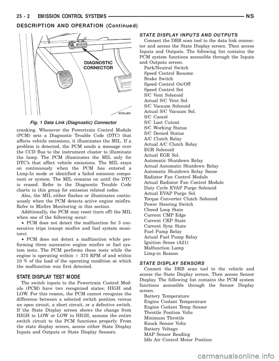
Connect the DRB scan tool to the data link connec-
tor and access the State Display screen. Then access
Inputs and Outputs. The following list contains the
PCM system functions accessible through the Inputs
and Outputs screen.
Park/Neutral Switch
Speed Control Resume
Brake Switch
Speed Control On/Off
Speed Control Set
S/C Vent Solenoid
Actual S/C Vent Sol.
S/C Vacuum Solenoid
Actual S/C Vacuum Sol.
S/C Cancel
S/C Last Cutout
S/C Working Status
S/C Denied Status
A/C Clutch Relay
Actual A/C Clutch Relay
EGR Solenoid
Actual EGR Sol.
Automatic Shutdown Relay
Actual Automatic Shutdown Relay
Automatic Shutdown Relay Sense
Radiator Fan Control Module
Actual Radiator Fan Control Module
Duty Cycle EVAP Purge Solenoid
Actual EVAP Purge Sol.
Torque Converter Clutch Solenoid
Power Steering Switch
Closed Loop State
Current CMP Edge
Current CKP State
Current Sync State
Fuel Pump Relay
Actual Fuel Pump Relay
Ignition Sense (A21)
Malfunction Lamp
Limp-in Reason
STATE DISPLAY SENSORS
Connect the DRB scan tool to the vehicle and
access the State Display screen. Then access Sensor
Display. The following list contains the PCM system
functions accessible through the Sensor Display
screen.
Battery Temperature
Engine Coolant Temperature
Engine Coolant Temp Sensor
Throttle Position Volts
Minimum Throttle
Knock Sensor Volts
Battery Voltage
MAP Sensor Reading
Idle Air Control Motor Position
Fig. 1 Data Link (Diagnostic) Connector
25 - 2 EMISSION CONTROL SYSTEMSNS
DESCRIPTION AND OPERATION (Continued)
Page 1907 of 1938

Adaptive Fuel Factor
Barometric Pressure
Engine Speed
Module Spark Advance
Speed Control Target
Intake Air Temp Degrees
Intake Air Temp Volts
Charging System Goal
Theft Alarm Status
Map Sensor Voltage
Vehicle Speed
Throttle Opening (percentage)
TPS Calculated
Cam Timing Position
Target Idle
Time From Start To Run
Run Time At Stall
Injector Pulse-width
Upstream O2S Volts
Downstream O2S Volts
Closed Loop Timer
Short Term Adaptive
Current Adaptive Cell
Adaptive Memory Cell 0
Adaptive Memory Cell 1
Adaptive Memory Cell 2
Adaptive Memory Cell 3
Adaptive Memory Cell 4
Adaptive Memory Cell 5
Adaptive Memory Cell 6
Adaptive Memory Cell 7
Adaptive Memory Cell 8
Adaptive Memory Cell 9
Adaptive Memory Cell 10
Adaptive Memory Cell 11
Adaptive Memory Cell 12
Adaptive Memory Cell 13
Adaptive Memory Cell 14
Adaptive Memory Cell 15
Purge Free Idle Cell
Purge Free Cell 2 (corresponds to memory cell 2)
Purge Free Cell 3 (corresponds to memory cell 5)
Target IAC Steps
Retard Cylinder (1)
Retard Cylinder (2)
Retard Cylinder (3)
Retard Cylinder (4)
Retard Cylinder (5)
Retard Cylinder (6)CIRCUIT ACTUATION TEST MODE
The Circuit Actuation Test Mode checks for proper
operation of output circuits or devices the Powertrain
Control Module (PCM) may not internally recognize.
The PCM attempts to activate these outputs and
allow an observer to verify proper operation. Most of
the tests provide an audible or visual indication of
device operation (click of relay contacts, fuel spray,
etc.). Except for intermittent conditions, if a device
functions properly during testing, assume the device,
its associated wiring, and driver circuit work cor-
rectly.
DIAGNOSTIC TROUBLE CODES
A Diagnostic Trouble Code (DTC) indicates the
PCM has recognized an abnormal condition in the
system.
The preferred and most accurate method of retriev-
ing a DTC is by using the DRB scan tool. The scan
tool supplies detailed diagnostic information which
can be used to more accurately diagnose causes for a
DTC.
Remember that DTC's are the results of a sys-
tem or circuit failure, but do not directly iden-
tify the failed component or components.
NOTE: For a list of DTC's, refer to the charts in this
section.
BULB CHECK
Each time the ignition key is turned to the ON
position, the malfunction indicator (check engine)
lamp on the instrument panel should illuminate for
approximately 2 seconds then go out. This is done for
a bulb check.
OBTAINING DTC'S USING DRB SCAN TOOL
(1) Connect the DRB scan tool to the data link
(diagnostic) connector. This connector is located in
the passenger compartment; at the lower edge of
instrument panel; near the steering column.
(2) Turn the ignition switch on and access the
ªRead Faultº screen.
(3) Record all the DTC's and ªfreeze frameº infor-
mation shown on the DRB scan tool.
(4) To erase DTC's, use the ªErase Trouble Codeº
data screen on the DRB scan tool.Do not erase any
DTC's until problems have been investigated
and repairs have been performed.
NSEMISSION CONTROL SYSTEMS 25 - 3
DESCRIPTION AND OPERATION (Continued)
Page 1920 of 1938

the inlet. This results in maximum vapor flow
through the valve (Fig. 9).
CRANKCASE VENT FILTER
All engines use filtered air to vent the crankcase.
The filtered air is drawn through the resonator
assembly located between the air cleaner and throttle
body.
VEHICLE EMISSION CONTROL INFORMATION
LABEL
All models have a Vehicle Emission Control Infor-
mation (VECI) Label. Chrysler permanently attaches
the label in the engine compartment. It cannot be
removed without defacing information and destroying
the label.
The label contains the vehicle's emission specifica-
tions and vacuum hose routings. All hoses must be
connected and routed according to the label.
DIAGNOSIS AND TESTING
LEAK DETECTION PUMP
Refer to the appropriate Powertrain Diagnostic
Procedures Manual for testing procedures.
PCV VALVE TEST
WARNING: APPLY PARKING BRAKE AND/OR
BLOCK WHEELS BEFORE PERFORMING ANY TEST
OR ADJUSTMENT WITH THE ENGINE OPERATING.
With the engine idling, remove the PCV valve from
its attaching point. If the valve is operating properly,
a hissing noise will be heard and a strong vacuum
felt when placing a finger over the valve inlet (Fig.
10). With the engine off, shake the valve. The valve
should rattle when shaken. Replace the valve if it
does not operate properly.Do not attempt to clean
the PCV valve.
REMOVAL AND INSTALLATION
LEAK DETECTION PUMP REPLACEMENT
REMOVAL
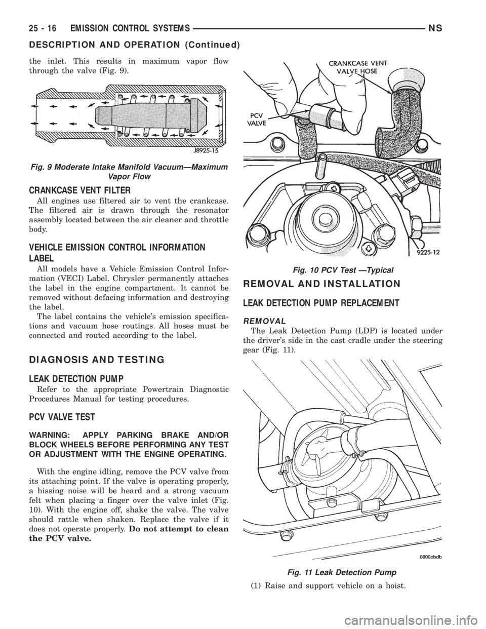
The Leak Detection Pump (LDP) is located under
the driver's side in the cast cradle under the steering
gear (Fig. 11).
(1) Raise and support vehicle on a hoist.
Fig. 9 Moderate Intake Manifold VacuumÐMaximum
Vapor Flow
Fig. 10 PCV Test ÐTypical
Fig. 11 Leak Detection Pump
25 - 16 EMISSION CONTROL SYSTEMSNS
DESCRIPTION AND OPERATION (Continued)
Page 1923 of 1938

the amount of EGR supplied to the engine. This pro-
vides the correct amount of exhaust gas recirculation
for different operating conditions.
This system does not allow EGR at idle. The EGR
systems can operate at all coolant temperatures
above 60ÉF as long as the battery ambient tempera-
ture is above 7ÉF.
DIAGNOSIS AND TESTING
EGR SYSTEM ON-BOARD DIAGNOSTICS
The PCM performs an on-board diagnostic check of
the EGR system. The diagnostic system uses the
electronic EGR transducer for the system tests.
The diagnostic check activates only during selected
engine/driving conditions. When the conditions are
met, the PCM energizes the transducer solenoid to
disable the EGR. The PCM checks for a change in
the heated oxygen sensor signal. If the air-fuel mix-
ture goes lean, the PCM will attempt to enrichen the
mixture. The PCM registers a Diagnostic Trouble
Code (DTC) if the EGR system is not operating cor-
rectly. After registering a DTC, the PCM turns on the
malfunction indicator (Check Engine) lamp after 2
consecutive trips. There are 2 types of failures sensed
by the PCM. The first is a short or open in the elec-
trical solenoid circuit. The second is a mechanical
failure or loss of vacuum. The Malfunction Indicator
Lamp (MIL) indicates the need for service.
If a problem is indicated by the MIL and a DTC for
the EGR system is set, check for proper operation of
the EGR system. Use the System Test, EGR Gas
Flow Test. If the EGR system tests properly, check
the system using the DRB scan tool. Refer to
On-Board Diagnosis sections in this Group. Also,
refer to the DRB scan tool and the appropriate Pow-
ertrain Diagnostics Procedure manual.
EGR SYSTEM TEST
WARNING: APPLY PARKING BRAKE AND/OR
BLOCK WHEELS BEFORE TESTING THE EGR SYS-
TEM.
(1) Check the condition of all EGR system hoses
and tubes for leaks, cracks, kinks and hardening of
rubber hoses. Repair and correct these conditions
before performing any tests.
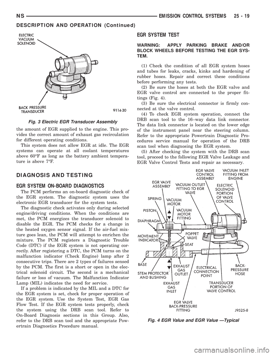
(2) Be sure the hoses at both the EGR valve and
EGR valve control are connected to the proper fit-
tings (Fig. 4).
(3) Be sure the electrical connector is firmly con-
nected at the valve control.
(4) To check EGR system operation, connect the
DRB scan tool to the 16±way data link connector.
The data link connector is located on the lower edge
of the instrument panel near the steering column.
Refer to the appropriate Powertrain Diagnostic Pro-
cedures service manual for operation of the DRB
scan tool when diagnosing the EGR system.
(5) After checking the system with the DRB scan
tool, proceed to the following EGR Valve Leakage and
EGR Valve Control Tests and repair as necessary.
Fig. 3 Electric EGR Transducer Assembly
Fig. 4 EGR Value and EGR Value ÐTypical
NSEMISSION CONTROL SYSTEMS 25 - 19
DESCRIPTION AND OPERATION (Continued)