1996 CHRYSLER VOYAGER power steering
[x] Cancel search: power steeringPage 1473 of 1938
STEERING
CONTENTS
page
POWER STEERINGÐ2.5L VM DIESEL....... 1
POWER STEERINGÐ2.5L VM DIESEL
INDEX
page page
GENERAL INFORMATION
POWER STEERING GEAR................ 1
POWER STEERING PUMP................ 1
STEERING GEAR OPERATIONÐRHD & LHD
VEHICLES........................... 1SERVICE PROCEDURES
POWER STEERING PUMP ± INITIAL
OPERATION.......................... 1
REMOVAL AND INSTALLATION
POWER STEERING PUMPÐ2.5L DIESEL..... 2
GENERAL INFORMATION
POWER STEERING PUMP
The power steering pump used with the 2.5L VM
Diesel engine operates the same way as the power
steering pump used with the 2.5/4.0L gasoline
engines. Refer to the Description and Operation sec-
tion for the 2.5/4.0L gasoline engine power steering
pump for more information.
STEERING GEAR OPERATIONÐRHD & LHD
VEHICLES
NOTE: The power steering gear should NOT be ser-
viced or adjusted. If a malfunction or oil leak
occurs, the complete steering gear should be
replaced.
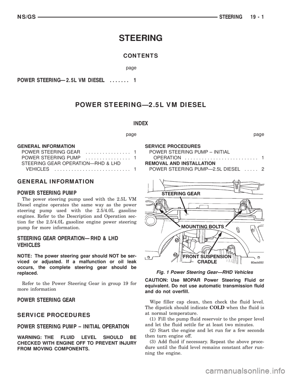
Refer to the Power Steering Gear in group 19 for
more information
POWER STEERING GEAR
SERVICE PROCEDURES
POWER STEERING PUMP ± INITIAL OPERATION
WARNING: THE FLUID LEVEL SHOULD BE
CHECKED WITH ENGINE OFF TO PREVENT INJURY
FROM MOVING COMPONENTS.CAUTION: Use MOPAR Power Steering Fluid or
equivalent. Do not use automatic transmission fluid
and do not overfill.
Wipe filler cap clean, then check the fluid level.
The dipstick should indicateCOLDwhen the fluid is
at normal temperature.
(1) Fill the pump fluid reservoir to the proper level
and let the fluid settle for at least two minutes.
(2) Start the engine and let run for a few seconds
then turn engine off.
(3) Add fluid if necessary. Repeat the above proce-
dure until the fluid level remains constant after run-
ning the engine.
Fig. 1 Power Steering GearÐRHD Vehicles
NS/GSSTEERING 19 - 1
Page 1474 of 1938
(4) Raise the front wheels off the ground.
(5) Slowly turn the steering wheel right and left,
lightly contacting the wheel stops at least 20 times.
(6) Check the fluid level add if necessary.
(7) Lower the vehicle, start the engine and turn
the steering wheel slowly from lock to lock.
(8) Stop the engine and check the fluid level and
refill as required.
(9) If the fluid is extremely foamy or milky look-
ing, allow the vehicle to stand a few minutes and
repeat the procedure.
CAUTION: Do not run a vehicle with foamy fluid for
an extended period. This may cause pump damage.
REMOVAL AND INSTALLATION
POWER STEERING PUMPÐ2.5L DIESEL
NOTE: The power steering pump is mounted below
the fuel pump on the left side of the engine. The
vehicle should be raised on a hoist to access the
pump from below.
REMOVAL
(1) Remove serpentine drive belt. Refer to Group 7,
Cooling System, for procedure.
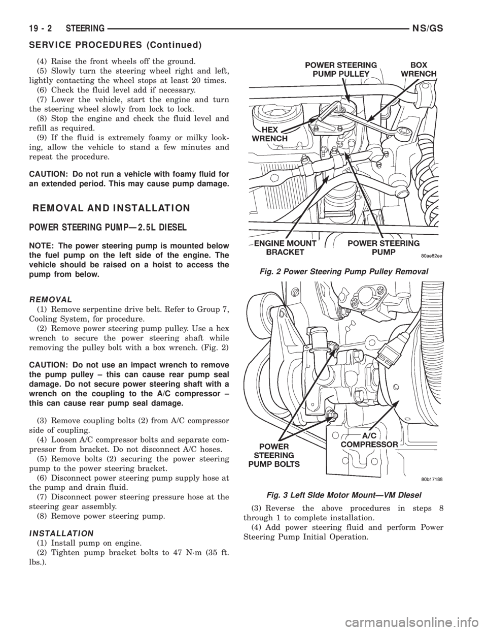
(2) Remove power steering pump pulley. Use a hex
wrench to secure the power steering shaft while
removing the pulley bolt with a box wrench. (Fig. 2)
CAUTION: Do not use an impact wrench to remove
the pump pulley ± this can cause rear pump seal
damage. Do not secure power steering shaft with a
wrench on the coupling to the A/C compressor ±
this can cause rear pump seal damage.
(3) Remove coupling bolts (2) from A/C compressor
side of coupling.
(4) Loosen A/C compressor bolts and separate com-
pressor from bracket. Do not disconnect A/C hoses.
(5) Remove bolts (2) securing the power steering
pump to the power steering bracket.
(6) Disconnect power steering pump supply hose at
the pump and drain fluid.
(7) Disconnect power steering pressure hose at the
steering gear assembly.
(8) Remove power steering pump.
INSTALLATION
(1) Install pump on engine.
(2) Tighten pump bracket bolts to 47 N´m (35 ft.
lbs.).(3) Reverse the above procedures in steps 8
through 1 to complete installation.
(4) Add power steering fluid and perform Power
Steering Pump Initial Operation.
Fig. 2 Power Steering Pump Pulley Removal
Fig. 3 Left SIde Motor MountÐVM DIesel
19 - 2 STEERINGNS/GS
SERVICE PROCEDURES (Continued)
Page 1478 of 1938
GEARSHIFT AND PARKING LOCK CONTROLS
The transaxle is controlled by a lever type gear-
shift incorporated within the steering column. The
control has six selector lever positions: P (park), R
(reverse), N (neutral), and D (drive), 2 (second), and
1 (first). The parking lock is applied by moving the
selector lever past a gate to the P position.Do not
apply the parking lock until the vehicle has
stopped; otherwise, a severe ratchet noise will
occur.
TORQUE CONVERTER CLUTCH SOLENOID WIRING
CONNECTOR
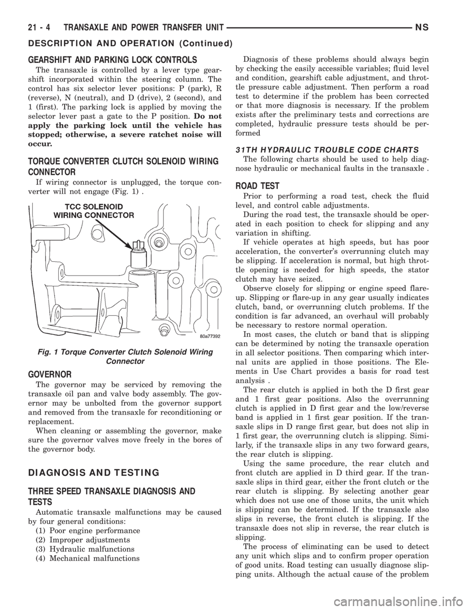
If wiring connector is unplugged, the torque con-
verter will not engage (Fig. 1) .
GOVERNOR
The governor may be serviced by removing the
transaxle oil pan and valve body assembly. The gov-
ernor may be unbolted from the governor support
and removed from the transaxle for reconditioning or
replacement.
When cleaning or assembling the governor, make
sure the governor valves move freely in the bores of
the governor body.
DIAGNOSIS AND TESTING
THREE SPEED TRANSAXLE DIAGNOSIS AND
TESTS
Automatic transaxle malfunctions may be caused
by four general conditions:
(1) Poor engine performance
(2) Improper adjustments
(3) Hydraulic malfunctions
(4) Mechanical malfunctionsDiagnosis of these problems should always begin
by checking the easily accessible variables; fluid level
and condition, gearshift cable adjustment, and throt-
tle pressure cable adjustment. Then perform a road
test to determine if the problem has been corrected
or that more diagnosis is necessary. If the problem
exists after the preliminary tests and corrections are
completed, hydraulic pressure tests should be per-
formed
31TH HYDRAULIC TROUBLE CODE CHARTS
The following charts should be used to help diag-
nose hydraulic or mechanical faults in the transaxle .
ROAD TEST
Prior to performing a road test, check the fluid
level, and control cable adjustments.
During the road test, the transaxle should be oper-
ated in each position to check for slipping and any
variation in shifting.
If vehicle operates at high speeds, but has poor
acceleration, the converter's overrunning clutch may
be slipping. If acceleration is normal, but high throt-
tle opening is needed for high speeds, the stator
clutch may have seized.
Observe closely for slipping or engine speed flare-
up. Slipping or flare-up in any gear usually indicates
clutch, band, or overrunning clutch problems. If the
condition is far advanced, an overhaul will probably
be necessary to restore normal operation.
In most cases, the clutch or band that is slipping
can be determined by noting the transaxle operation
in all selector positions. Then comparing which inter-
nal units are applied in those positions. The Ele-
ments in Use Chart provides a basis for road test
analysis .
The rear clutch is applied in both the D first gear
and 1 first gear positions. Also the overrunning
clutch is applied in D first gear and the low/reverse
band is applied in 1 first gear position. If the tran-
saxle slips in D range first gear, but does not slip in
1 first gear, the overrunning clutch is slipping. Simi-
larly, if the transaxle slips in any two forward gears,
the rear clutch is slipping.
Using the same procedure, the rear clutch and
front clutch are applied in D third gear. If the tran-
saxle slips in third gear, either the front clutch or the
rear clutch is slipping. By selecting another gear
which does not use one of those units, the unit which
is slipping can be determined. If the transaxle also
slips in reverse, the front clutch is slipping. If the
transaxle does not slip in reverse, the rear clutch is
slipping.
The process of eliminating can be used to detect
any unit which slips and to confirm proper operation
of good units. Road testing can usually diagnose slip-
ping units. Although the actual cause of the problem
Fig. 1 Torque Converter Clutch Solenoid Wiring
Connector
21 - 4 TRANSAXLE AND POWER TRANSFER UNITNS
DESCRIPTION AND OPERATION (Continued)
Page 1548 of 1938
TORQUE MANAGEMENT
Most 41TE transaxles utilize torque management.
Torque management is a unique function of the Pow-
ertrain Control Module (PCM). The PCM receives
output signals from the Transmission Control Module
(TCM) and many various engine sensors. The PCM
evaluates these signals and decides if it is necessary
to decrease the output of the engine's torque. This
reduction in torque does not interfere with the nor-
mal operation of the vehicle. This reduction in torque
will prolong the life of the drivetrain components.
Torque reduction is not noticeable in normal driving
functions. The torque reduction function shuts off
above 16 MPH.
ON-BOARD DIAGNOSTICS
This vehicle utilizes a diagnostic system called
OBDII. The powertrain control module communicates
with the Transmission Control Module. Whenever
the transaxle sets a fault in the Transmission Con-
trol Module (dependent on which fault is set), the
powertrain control module will turn on a MIL (Mal-
function Indicator Lamp) on the instrument cluster.
By reading the code in the powertrain control module
it will tell you where the fault occurred. If the fault
occurred in the transaxle, the controller will read a
CODE 45.For further information regarding OBDII,
refer to Group 25, Emission Systems.
These controls provide comprehensive, on-board
transaxle diagnostics. The information available can
aid in transaxle diagnosis. For example, apply ele-
ment buildup rate indicates solenoid performance.
Also included are self diagnostic functions. Self diag-
nostics allow the technician to test the condition of
the electronic controls. The Transmission Control
Module continuously monitors its critical functions. It
also records any malfunctions, and the number of
engine starts since the last malfunction. This allows
the technician to use the information in the event of
a customer complaint.
TRANSMISSION CONTROL MODULE
Do not interchange Transmission Control Modules
with previous year transmission control modules. If a
same year TCM is being used from a different vehi-
cle, the following procedures must be performed:
²Quick Learn Procedure
²Electronic Pinion Factor Procedure
The Transmission Control Module is located on the
right inner fender panel, in the engine compartment.
It is held in place by four mounting screws.NOTE: If the Transmission Control Module has
been replaced, the following procedures must be
performed:
²Quick Learn Procedure: This procedure will
allow the transmission control module to learn the
characteristics of the vehicle.
²Electronic Pinion Factor Procedure: This proce-
dure will reprogram the TCM to compensate for dif-
ferent tire sizes and final drive ratios.
GEARSHIFT AND PARKING LOCK CONTROLS
The transaxle is controlled by a lever type gear-
shift incorporated within the steering column. The
control has six selector lever positions: P (park), R
(reverse), N (neutral), and D (drive), 2 (second), and
1 (first). The parking lock is applied by moving the
selector lever past a gate to the P position.Do not
apply the parking lock until the vehicle has
stopped; otherwise, a severe ratchet noise will
occur.
TRANSMISSION RANGE SENSOR
The 41TE transaxle is equipped with a transmis-
sion range sensor that is located on top of the valve
body. This sensor will allow for accurate transmission
gear position measurement.
To service the transmission range sensor (TRS),
you must remove the valve body. For repair proce-
dures, refer to the Removal and Installation section
within this group.
Also located within the TRS is a transmission tem-
perature sensor. This sensor is used to measure the
transmission fluid sump temperature. The transmis-
sion temperature sensor is serviced with the TRS as
a unit.
SHIFT POSITION INDICATOR
The shifter position indicator is located in the
instrument cluster. The shifter position indicator out-
lines with a box the gear position the transaxle man-
ual valve lever is in.
The transmission range sensor (located on the
valvebody) sends a signal to the TCM on the position
of the transaxle manual valve lever. The TCM
receives the switch signal and processes the data.
The TCM sends the Shift Lever Position (SLP) infor-
mation to the BCM via the CCD bus. The BCM then
outlines with a box the appropriate shifter position
indicator in the instrument cluster.
To replace the shifter position indicator, refer to
Group 8E, Instrument Panel And Gauges.
21 - 74 TRANSAXLE AND POWER TRANSFER UNITNS
DESCRIPTION AND OPERATION (Continued)
Page 1557 of 1938
²The shift lever position must stay until
prompted to shift to overdrive
²The shift lever position must stay in overdrive
after the Shift to Overdrive prompt until the DRBIII
indicates the procedure is complete
²The calculated oil temperature must be above
60É and below 200É
(1) Plug the DRBIII scan tool into the data link
connector. The connector is located under the instru-
ment panel.
(2) Go to the Transmission screen.
(3) Go to the Miscellaneous screen.
(4) Select Quick Learn Procedure. Follow the
instructions of the DRBIII to perform the Quick
Learn Procedure.
PINION FACTOR PROCEDURE
The vehicle speed readings for the speedometer are
taken from the output speed sensor. The TCM must
be calibrated to the different combinations of equip-
ment available. A procedure has been developed
called Pinion Factor. It allows the technician to set
the Transmission Control Module initial setting so
that the speedometer readings will be correct.
Failure to perform this procedure will cause a No
Speedometer Operation condition.
This procedure must be performed if the Transmis-
sion Control Module has been replaced.
To properly read or reset the Pinion Factor, it is
necessary to use a DRBIII scan tool. Perform the fol-
lowing steps with the DRBIII scan tool to read or
reset the Pinion Factor:
(1) Plug the DRBIII scan tool into the data link
connector located under the instrument panel.
(2) Select the Transmission menu.
(3) Select the Miscellaneous menu.
(4) Select Pinion Factor. Then follow the instruc-
tions on the DRBIII scan tool screen.
REMOVAL AND INSTALLATION
GEARSHIFT CABLE
REMOVAL
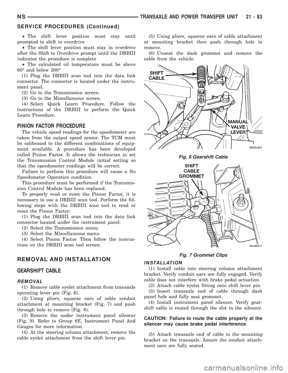
(1) Remove cable eyelet attachment from transaxle
operating lever pin (Fig. 6).
(2) Using pliers, squeeze ears of cable conduit
attachment at mounting bracket (Fig. 7) and push
through hole to remove (Fig. 8).
(3) Remove the under instrument panel silencer
(Fig. 9). Refer to Group 8E, Instrument Panel And
Gauges for more information.
(4) At the steering column attachment, remove the
cable eyelet attachment from the shift lever pin.(5) Using pliers, squeeze ears of cable attachment
at mounting bracket then push through hole to
remove.
(6) Unseat the dash grommet and remove the
cable from the vehicle.
INSTALLATION
(1) Install cable into steering column attachment
bracket. Verify conduit ears are fully engaged. Verify
cable does not interfere with brake pedal actuation.
(2) Attach cable eyelet fitting onto shift lever pin.
(3) Insert transaxle end of cable through dash
panel hole and fully seat grommet.
(4) Install instrument panel silencer. Verify gear-
shift cable is routed through the slot in the silencer.
CAUTION: Failure to route the cable properly at the
silencer may cause brake pedal interference.
(5) Attach transaxle end of cable to the mounting
bracket on the transaxle. Assure the conduit attach-
ment ears are fully seated.
Fig. 6 Gearshift Cable
Fig. 7 Grommet Clips
NSTRANSAXLE AND POWER TRANSFER UNIT 21 - 83
SERVICE PROCEDURES (Continued)
Page 1772 of 1938
(7) Tighten attaching bolts to 11 to 16 N´m (100 to
140 in. lbs.) torque.
HOOD LATCH STRIKER
REMOVAL
(1) Release hood latch and open hood.
(2) Remove bolts holding striker to inside of hood
(Fig. 44).
(3) Remove hood latch striker from vehicle.
INSTALLATION
(1) Position hood latch striker on vehicle.
(2) Install bolts to hold hood latch striker to hood.
(3) Align hood latch striker to engage smoothly
into hood latch.
(4) Verify hood operation and alignment. Adjust as
necessary.
(5) Tighten attaching bolts to 11 to 16 N´m (100 to
140 in. lbs.) torque.
HOOD RELEASE CABLE
REMOVAL
(1) Remove hood latch.
(2) Disengage cable end from hood latch locking
mechanism.
(3) Slide cable case end sideways in keyhole slot of
hood latch while pinching barb on cable case closed.
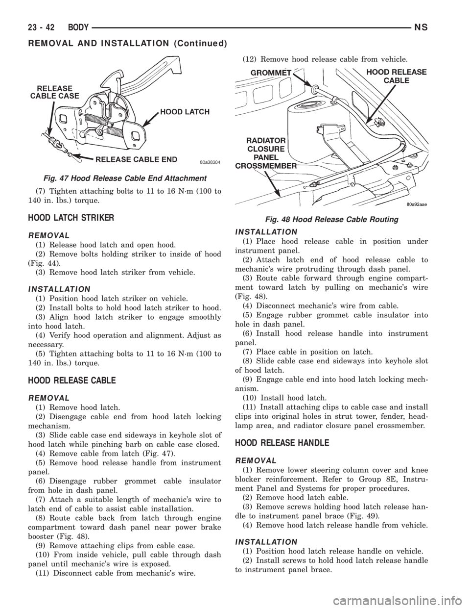
(4) Remove cable from latch (Fig. 47).
(5) Remove hood release handle from instrument
panel.
(6) Disengage rubber grommet cable insulator
from hole in dash panel.
(7) Attach a suitable length of mechanic's wire to
latch end of cable to assist cable installation.
(8) Route cable back from latch through engine
compartment toward dash panel near power brake
booster (Fig. 48).
(9) Remove attaching clips from cable case.
(10) From inside vehicle, pull cable through dash
panel until mechanic's wire is exposed.
(11) Disconnect cable from mechanic's wire.(12) Remove hood release cable from vehicle.
INSTALLATION
(1) Place hood release cable in position under
instrument panel.
(2) Attach latch end of hood release cable to
mechanic's wire protruding through dash panel.
(3) Route cable forward through engine compart-
ment toward latch by pulling on mechanic's wire
(Fig. 48).
(4) Disconnect mechanic's wire from cable.
(5) Engage rubber grommet cable insulator into
hole in dash panel.
(6) Install hood release handle into instrument
panel.
(7) Place cable in position on latch.
(8) Slide cable case end sideways into keyhole slot
of hood latch.
(9) Engage cable end into hood latch locking mech-
anism.
(10) Install hood latch.
(11) Install attaching clips to cable case and install
clips into original holes in strut tower, fender, head-
lamp area, and radiator closure panel crossmember.
HOOD RELEASE HANDLE
REMOVAL
(1) Remove lower steering column cover and knee
blocker reinforcement. Refer to Group 8E, Instru-
ment Panel and Systems for proper procedures.
(2) Remove hood latch cable.
(3) Remove screws holding hood latch release han-
dle to instrument panel brace (Fig. 49).
(4) Remove hood latch release handle from vehicle.
INSTALLATION
(1) Position hood latch release handle on vehicle.
(2) Install screws to hold hood latch release handle
to instrument panel brace.
Fig. 47 Hood Release Cable End Attachment
Fig. 48 Hood Release Cable Routing
23 - 42 BODYNS
REMOVAL AND INSTALLATION (Continued)
Page 1869 of 1938
pressor is driven off the back of the power steering
pump. A rubber flex coupling transfers the power from
the power steering pump to the compressor clutch.
COMPRESSOR HIGH-PRESSURE RELIEF VALVE
The High Pressure Relief Valve prevents damage
to the air conditioning system if excessive pressure
develops. Excessive pressure can be caused by con-
denser air flow blockage, refrigerant overcharge, or
air and moisture in the system.
The high pressure relief valve vents only a small
amount of refrigerant necessary to reduce system
pressure and then reseats itself. The majority of the
refrigerant is conserved in the system. The valve is
calibrated to vent at a pressure of 3450 to 4140 kPa
(500 to 600 psi). If a valve has vented a small
amount of refrigerant, it does not necessarily mean
the valve is defective.
The High Pressure Relief Valve is located on the
compressor manifold at the discharge passage.
NOTE: Special effort must be used to keep all
R-134a system components moisture-free. Moisture
in the oil is very difficult to remove and will cause a
reliability problem with the compressor.
CONDENSATE DRAIN
Condensation from the evaporator housing is
drained through the dash panel and on to the
ground. This drain must be kept open to prevent
water from collecting in the bottom of the housing.
If the drain is blocked condensate cannot drain,
causing water to back up and spill into the passenger
compartment. It is normal to see condensate drain-
age below the vehicle.
ENGINE COOLING SYSTEM REQUIREMENTS
To maintain ample temperature levels from the
heating-A/C system, the cooling system must be in
proper working order. Refer to Group 0, Lubrication
and Maintenance or Group 7, Cooling System of this
manual.
The use of a bug screen is not recommended. Any
obstructions forward of the condenser can reduce the
effectiveness of the air conditioning system.
EVAPORATOR PROBE
The Evaporator probe is located on the HVAC. The
probe prevents evaporator freeze-up by signaling the
Powertrain Control Module to cycle the compressor
ON and OFF. The probe monitors the temperature of
the refrigerant after expansion.
The evaporator probe is inserted into the evapora-
tor between the coils. The probe is a sealed unit and
cannot be adjusted or repaired. It must be replaced if
found defective.
HANDLING TUBING AND FITTINGS
Kinks in the refrigerant tubing or sharp bends in
the refrigerant hose lines will greatly reduce the
capacity of the entire system. High pressures are pro-
duced in the system when it is operating. Extreme
care must be exercised to make sure that all connec-
tions are pressure tight. Dirt and moisture can enter
the system when it is opened for repair or replace-
ment of lines or components. The refrigerant oil will
absorb moisture readily out of the air. This moisture
will convert into acids within a closed system.
CAUTION: The system must be completely empty
before opening any fitting or connection in the
refrigeration system. Open fittings with caution
even after the system has been emptied. If any
pressure is noticed as a fitting is loosened,
retighten fitting and evacuate the system again.
A good rule for the flexible hose lines is to keep
the radius of all bends at least 10 times the diame-
ter of the hose. Sharper bends will reduce the flow
of refrigerant. The flexible hose lines should be
routed so they are at least 3 inches (80 mm) from
the exhaust manifold. Inspect all flexible hose lines
to make sure they are in good condition and prop-
erly routed.
The use of correct wrenches when making con-
nections is very important. Improper wrenches or
improper use of wrenches can damage the fittings.
The internal parts of the A/C system will remain
stable as long as moisture-free refrigerant and
refrigerant oil is used. Abnormal amounts of dirt,
moisture or air can upset the chemical stability.
This may cause operational troubles or even seri-
ous damage if present in more than very small
quantities.
When opening a refrigeration system, have every-
thing you will need to repair the system ready. This
will minimize the amount of time the system must
be opened. Cap or plug all lines and fittings as
soon as they are opened. This will help prevent the
entrance of dirt and moisture. All new lines and
components should be capped or sealed until they
are ready to be used.
All tools, including the refrigerant dispensing
manifold, the manifold gauge set, and test hoses
should be kept clean and dry.
HVAC CONTROL MODULE
The HVAC control module regulates the operation
of the various actuator motors. The actuator motors
are used to move the mode, blend- air, and recirc.
doors (Fig. 2).
The control module is included in the A/C control
head located on the instrument panel. The control
head includes the blower speed switch, rear wiper
NS/GSHEATING AND AIR CONDITIONING 24 - 3
DESCRIPTION AND OPERATION (Continued)
Page 1888 of 1938
(3) Remove resistor block by inserting a flat blade
pry tool on the side of the resistor block and pushing
inward. Two guide lines are shown on the right hand
edge of the resistor block to help guide the blade
position. This will release the clips on the side of the
resistor block. Pull resistor block out.
INSTALLATION
For installation, reverse the above procedures.
Make sure the ªTOPº lettering is on the top of the
resistor. The coils on the Resistor Block should not be
contacting one another. Before installation, gently
separate the coils (with fingers only) if one coil is
contacting another.
BLOWER MOTOR WHEEL
The blower motor wheel is not serviced separately.
If the wheel needs to be replaced it is serviced as an
assembly of the blower motor. For service procedure
information, refer to Blower Motor Replacement in
this group.
COMPRESSOR (2.5L TURBO DIESEL)
REMOVAL
WARNING: REFER TO REFRIGERANT SERVICE
PROCEDURES FOR INFORMATION REGARDING
PROPER RECOVERY OF THE REFRIGERANT
BEFORE ATTEMPTING TO REMOVE THE COM-
PRESSOR.(1) Disconnect negative battery cable.
(2) Reclaim refrigerant.
(3) Raise vehicle on hoist.
(4) Remove refrigerant lines from compressor and
cap all lines (Fig. 10).
(5) Remove flex drive bolts from behind the power
steering pump (Fig. 20).
(6) Remove compressor mounting bolts (Fig. 20).
(7) pry compressor off of the dowel pins and
remove compressor.
INSTALLATION
(1) Transfer mounting spacer/bushings onto the
new compressor.
(2) Lift compressor into place and start compressor
mounting bolts. Do not tighten bolts at this time. The
compressor may have to be moved slightly to align
the flex drive bolts.
(3) Align compressor clutch with flex drive. Then
start both flex drive bolts. Tighten the bolts after
both flex drive bolts have been installed.
(4) Tighten compressor mounting bolts.
(5) Lower vehicle and install refrigerant lines.
Always replace O-rings and gaskets.
(6) Evacuate refrigerant system. Charge system
with the correct amount of R-134a refrigerant. The
refrigerant capacity is .91 kg.67 gm. (32 oz.62.0
oz.).
24 - 22 HEATING AND AIR CONDITIONINGNS/GS
REMOVAL AND INSTALLATION (Continued)