1996 CHRYSLER VOYAGER engine oil
[x] Cancel search: engine oilPage 1067 of 1938
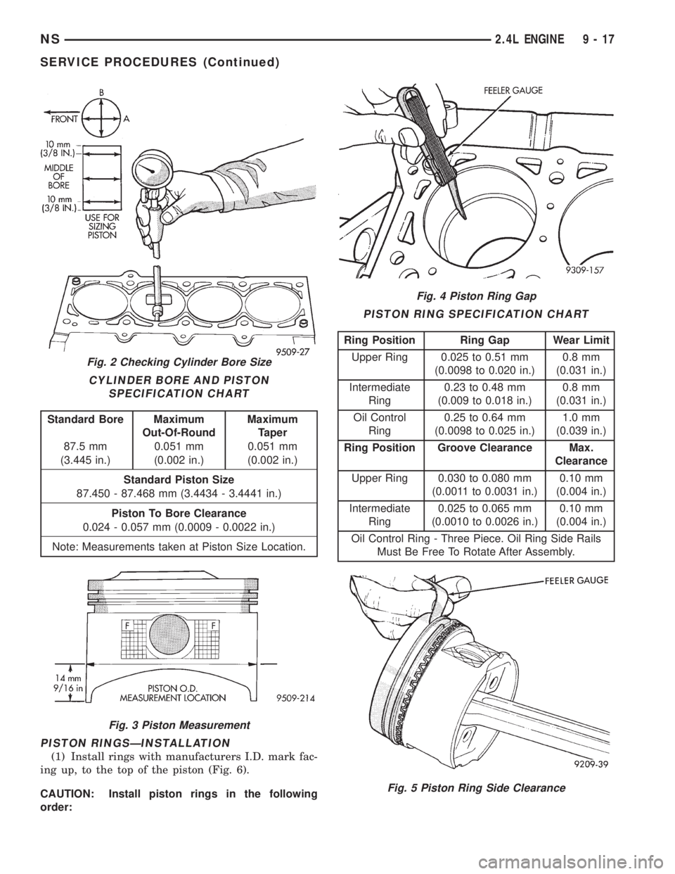
PISTON RINGSÐINSTALLATION
(1) Install rings with manufacturers I.D. mark fac-
ing up, to the top of the piston (Fig. 6).
CAUTION: Install piston rings in the following
order:
Fig. 2 Checking Cylinder Bore Size
CYLINDER BORE AND PISTON
SPECIFICATION CHART
Standard Bore Maximum
Out-Of-RoundMaximum
Taper
87.5 mm 0.051 mm 0.051 mm
(3.445 in.) (0.002 in.) (0.002 in.)
Standard Piston Size
87.450 - 87.468 mm (3.4434 - 3.4441 in.)
Piston To Bore Clearance
0.024 - 0.057 mm (0.0009 - 0.0022 in.)
Note: Measurements taken at Piston Size Location.
Fig. 3 Piston Measurement
Fig. 4 Piston Ring Gap
PISTON RING SPECIFICATION CHART
Ring Position Ring Gap Wear Limit
Upper Ring 0.025 to 0.51 mm
(0.0098 to 0.020 in.)0.8 mm
(0.031 in.)
Intermediate
Ring0.23 to 0.48 mm
(0.009 to 0.018 in.)0.8 mm
(0.031 in.)
Oil Control
Ring0.25 to 0.64 mm
(0.0098 to 0.025 in.)1.0 mm
(0.039 in.)
Ring Position Groove Clearance Max.
Clearance
Upper Ring 0.030 to 0.080 mm
(0.0011 to 0.0031 in.)0.10 mm
(0.004 in.)
Intermediate
Ring0.025 to 0.065 mm
(0.0010 to 0.0026 in.)0.10 mm
(0.004 in.)
Oil Control Ring - Three Piece. Oil Ring Side Rails
Must Be Free To Rotate After Assembly.
Fig. 5 Piston Ring Side Clearance
NS2.4L ENGINE 9 - 17
SERVICE PROCEDURES (Continued)
Page 1068 of 1938
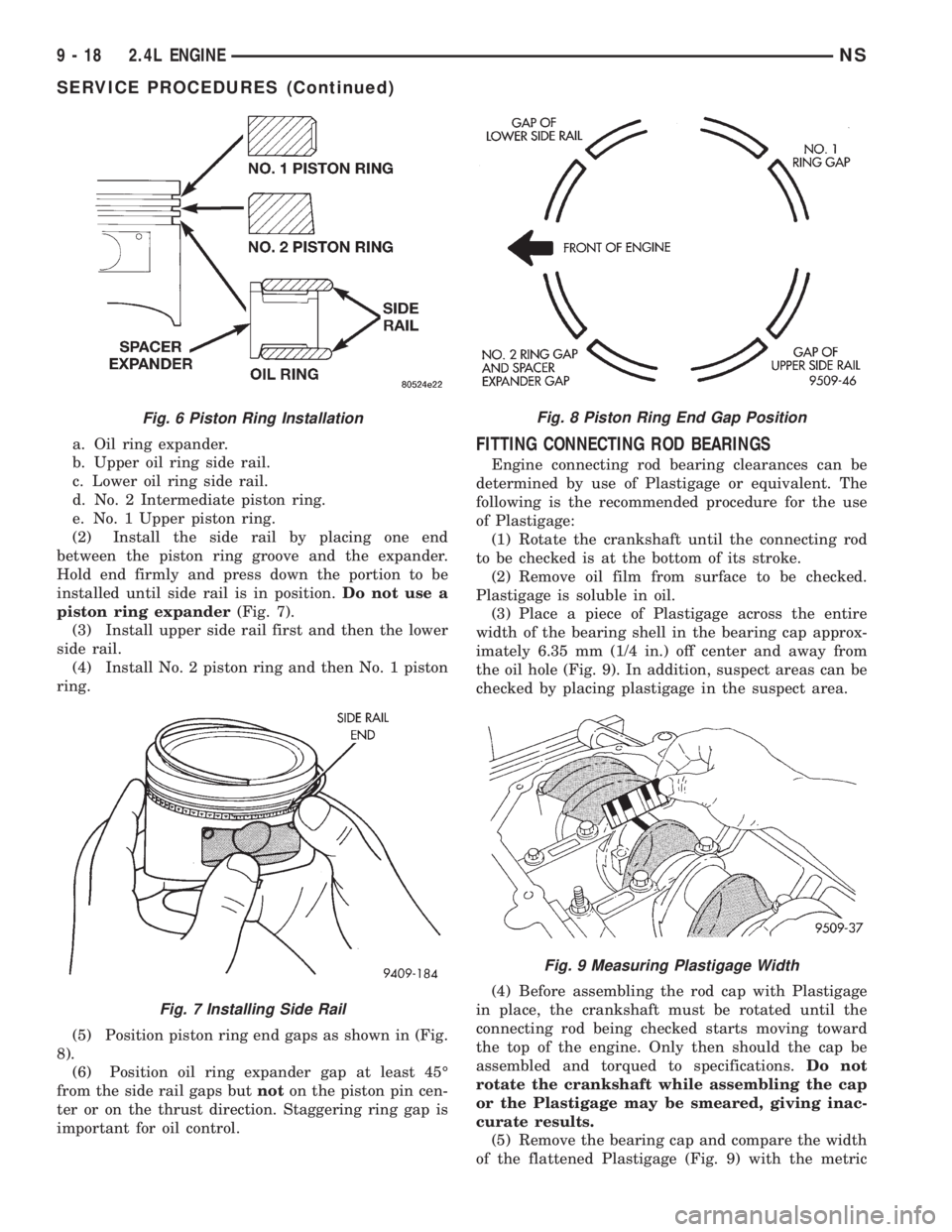
a. Oil ring expander.
b. Upper oil ring side rail.
c. Lower oil ring side rail.
d. No. 2 Intermediate piston ring.
e. No. 1 Upper piston ring.
(2) Install the side rail by placing one end
between the piston ring groove and the expander.
Hold end firmly and press down the portion to be
installed until side rail is in position.Do not use a
piston ring expander(Fig. 7).
(3) Install upper side rail first and then the lower
side rail.
(4) Install No. 2 piston ring and then No. 1 piston
ring.
(5) Position piston ring end gaps as shown in (Fig.
8).
(6) Position oil ring expander gap at least 45É
from the side rail gaps butnoton the piston pin cen-
ter or on the thrust direction. Staggering ring gap is
important for oil control.FITTING CONNECTING ROD BEARINGS
Engine connecting rod bearing clearances can be
determined by use of Plastigage or equivalent. The
following is the recommended procedure for the use
of Plastigage:
(1) Rotate the crankshaft until the connecting rod
to be checked is at the bottom of its stroke.
(2) Remove oil film from surface to be checked.
Plastigage is soluble in oil.
(3) Place a piece of Plastigage across the entire
width of the bearing shell in the bearing cap approx-
imately 6.35 mm (1/4 in.) off center and away from
the oil hole (Fig. 9). In addition, suspect areas can be
checked by placing plastigage in the suspect area.
(4) Before assembling the rod cap with Plastigage
in place, the crankshaft must be rotated until the
connecting rod being checked starts moving toward
the top of the engine. Only then should the cap be
assembled and torqued to specifications.Do not
rotate the crankshaft while assembling the cap
or the Plastigage may be smeared, giving inac-
curate results.
(5) Remove the bearing cap and compare the width
of the flattened Plastigage (Fig. 9) with the metric
Fig. 6 Piston Ring Installation
Fig. 7 Installing Side Rail
Fig. 8 Piston Ring End Gap Position
Fig. 9 Measuring Plastigage Width
9 - 18 2.4L ENGINENS
SERVICE PROCEDURES (Continued)
Page 1069 of 1938
scale provided on the package. Locate the band clos-
est to the same width. This band shows the amount
of clearance in thousandths of a millimeter. Differ-
ences in readings between the ends indicate the
amount of taper present. Record all readings taken.
Refer to Engine Specifications.Plastigage gener-
ally is accompanied by two scales. One scale is
in inches, the other is a metric scale.
(6) Plastigage is available in a variety of clearance
ranges. The 0.025-0.076 mm (.001-.003 in.) is usually
the most appropriate for checking engine bearing
proper specifications.
FITTING MAIN BEARINGS
Refer to the Engine General Information Section
for Measuring Main Bearings. For Crankshaft speci-
fications refer to Crankshaft Specification Chart.
CRANKSHAFT MAIN BEARINGS
The crankshaft is supported in five main bearings.
All upper and lower bearing shells in the crankcase
have oil grooves. The number three lower main
thrust bearing is plain. Crankshaft end play is con-
trolled by a flanged bearing on the number three
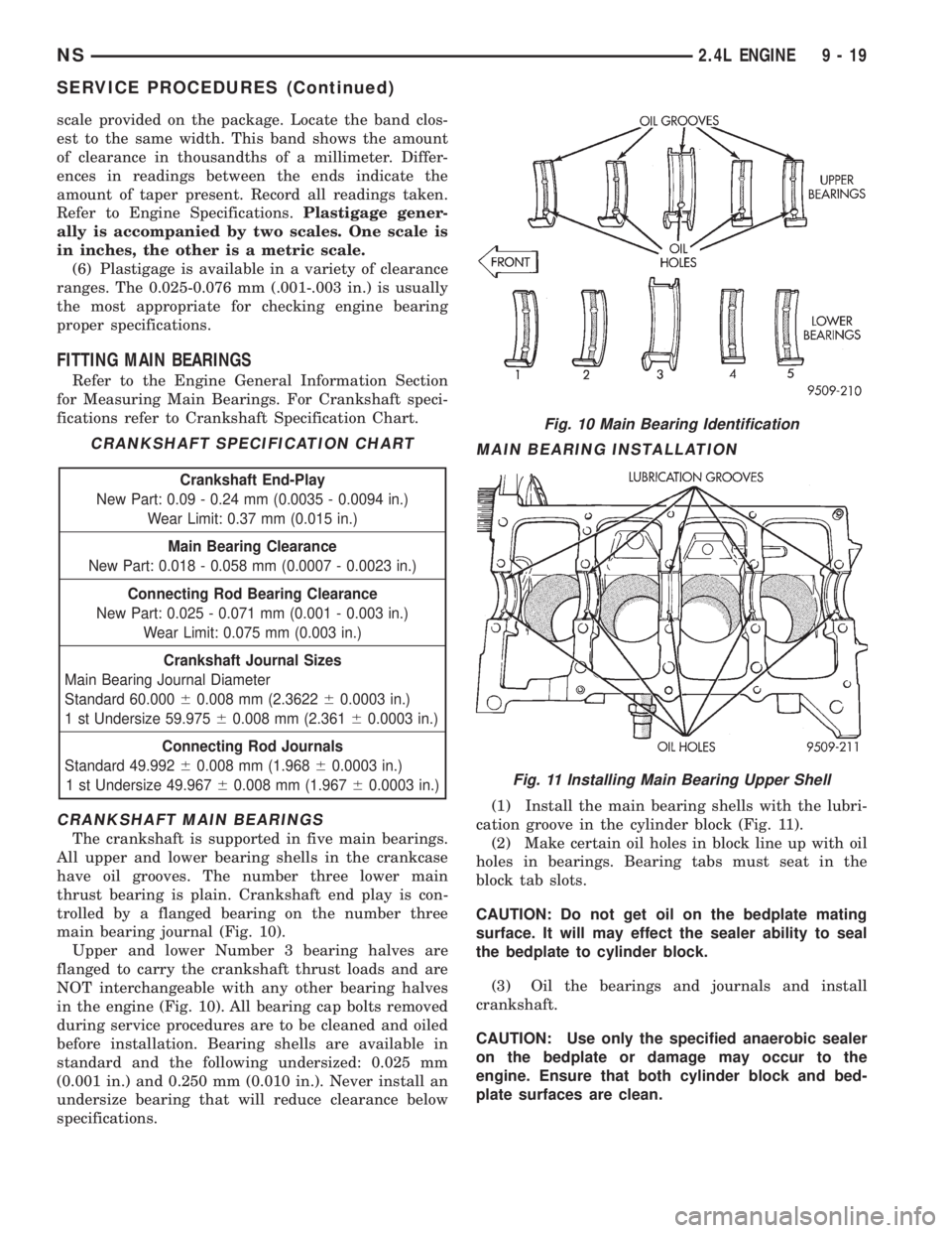
main bearing journal (Fig. 10).
Upper and lower Number 3 bearing halves are
flanged to carry the crankshaft thrust loads and are
NOT interchangeable with any other bearing halves
in the engine (Fig. 10). All bearing cap bolts removed
during service procedures are to be cleaned and oiled
before installation. Bearing shells are available in
standard and the following undersized: 0.025 mm
(0.001 in.) and 0.250 mm (0.010 in.). Never install an
undersize bearing that will reduce clearance below
specifications.
MAIN BEARING INSTALLATION
(1) Install the main bearing shells with the lubri-
cation groove in the cylinder block (Fig. 11).
(2) Make certain oil holes in block line up with oil
holes in bearings. Bearing tabs must seat in the
block tab slots.
CAUTION: Do not get oil on the bedplate mating
surface. It will may effect the sealer ability to seal
the bedplate to cylinder block.
(3) Oil the bearings and journals and install
crankshaft.
CAUTION: Use only the specified anaerobic sealer
on the bedplate or damage may occur to the
engine. Ensure that both cylinder block and bed-
plate surfaces are clean.
CRANKSHAFT SPECIFICATION CHART
Crankshaft End-Play
New Part: 0.09 - 0.24 mm (0.0035 - 0.0094 in.)
Wear Limit: 0.37 mm (0.015 in.)
Main Bearing Clearance
New Part: 0.018 - 0.058 mm (0.0007 - 0.0023 in.)
Connecting Rod Bearing Clearance
New Part: 0.025 - 0.071 mm (0.001 - 0.003 in.)
Wear Limit: 0.075 mm (0.003 in.)
Crankshaft Journal Sizes
Main Bearing Journal Diameter
Standard 60.00060.008 mm (2.362260.0003 in.)
1 st Undersize 59.97560.008 mm (2.36160.0003 in.)
Connecting Rod Journals
Standard 49.99260.008 mm (1.96860.0003 in.)
1 st Undersize 49.96760.008 mm (1.96760.0003 in.)
Fig. 10 Main Bearing Identification
Fig. 11 Installing Main Bearing Upper Shell
NS2.4L ENGINE 9 - 19
SERVICE PROCEDURES (Continued)
Page 1070 of 1938
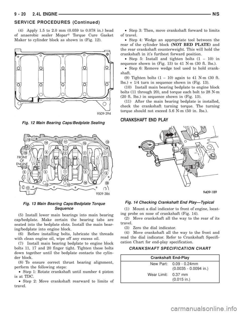
(4) Apply 1.5 to 2.0 mm (0.059 to 0.078 in.) bead
of anaerobic sealer MopartTorque Cure Gasket
Maker to cylinder block as shown in (Fig. 12).
(5) Install lower main bearings into main bearing
cap/bedplate. Make certain the bearing tabs are
seated into the bedplate slots. Install the main bear-
ing/bedplate into engine block.
(6) Before installing bolts, lubricate the threads
with clean engine oil, wipe off any excess oil.
(7) Install main bearing bedplate to engine block
bolts 11, 17 and 20 finger tight. Tighten these bolts
down together until the bedplate contacts the cylin-
der block.
(8) To ensure correct thrust bearing alignment,
perform the following steps:
²Step 1: Rotate crankshaft until number 4 piston
is at TDC.
²Step 2: Move crankshaft rearward to limits of
travel.²Step 3: Then, move crankshaft forward to limits
of travel.
²Step 4: Wedge an appropriate tool between the
rear of the cylinder block(NOT BED PLATE)and
the rear crankshaft counterweight. This will hold the
crankshaft in it's furthest forward position.
²Step 5: Install and tighten bolts (1 ± 10) in
sequence shown in (Fig. 13) to 41 N´m (30 ft. lbs.).
²Step 6: Remove wedge tool used to hold crank-
shaft.
(9) Tighten bolts (1 ± 10) again to 41 N´m (30 ft.
lbs.) + 1/4 turn in sequence shown in (Fig. 13).
(10) Install main bearing bedplate to engine block
bolts (11 through 20), and torque each bolt to 28 N´m
(20 ft. lbs.) in sequence shown in (Fig. 13).
(11) After the main bearing bedplate is installed,
check the crankshaft turning torque. The turning
torque should not exceed 5.6 N´m (50 in. lbs.).
CRANKSHAFT END PLAY
(1) Mount a dial indicator to front of engine, locat-
ing probe on nose of crankshaft (Fig. 14).
(2) Move crankshaft all the way to the rear of its
travel.
(3) Zero the dial indicator.
(4) Move crankshaft all the way to the front and
read the dial indicator. Refer to Crankshaft Specifi-
cation Chart for end-play specification.
Fig. 12 Main Bearing Caps/Bedplate Sealing
Fig. 13 Main Bearing Caps/Bedplate Torque
SequenceFig. 14 Checking Crankshaft End PlayÐTypical
CRANKSHAFT SPECIFICATION CHART
Crankshaft End-Play
New Part: 0.09 - 0.24mm
(0.0035 - 0.0094 in.)
Wear Limit: 0.37 mm
(0.015 in.)
9 - 20 2.4L ENGINENS
SERVICE PROCEDURES (Continued)
Page 1073 of 1938
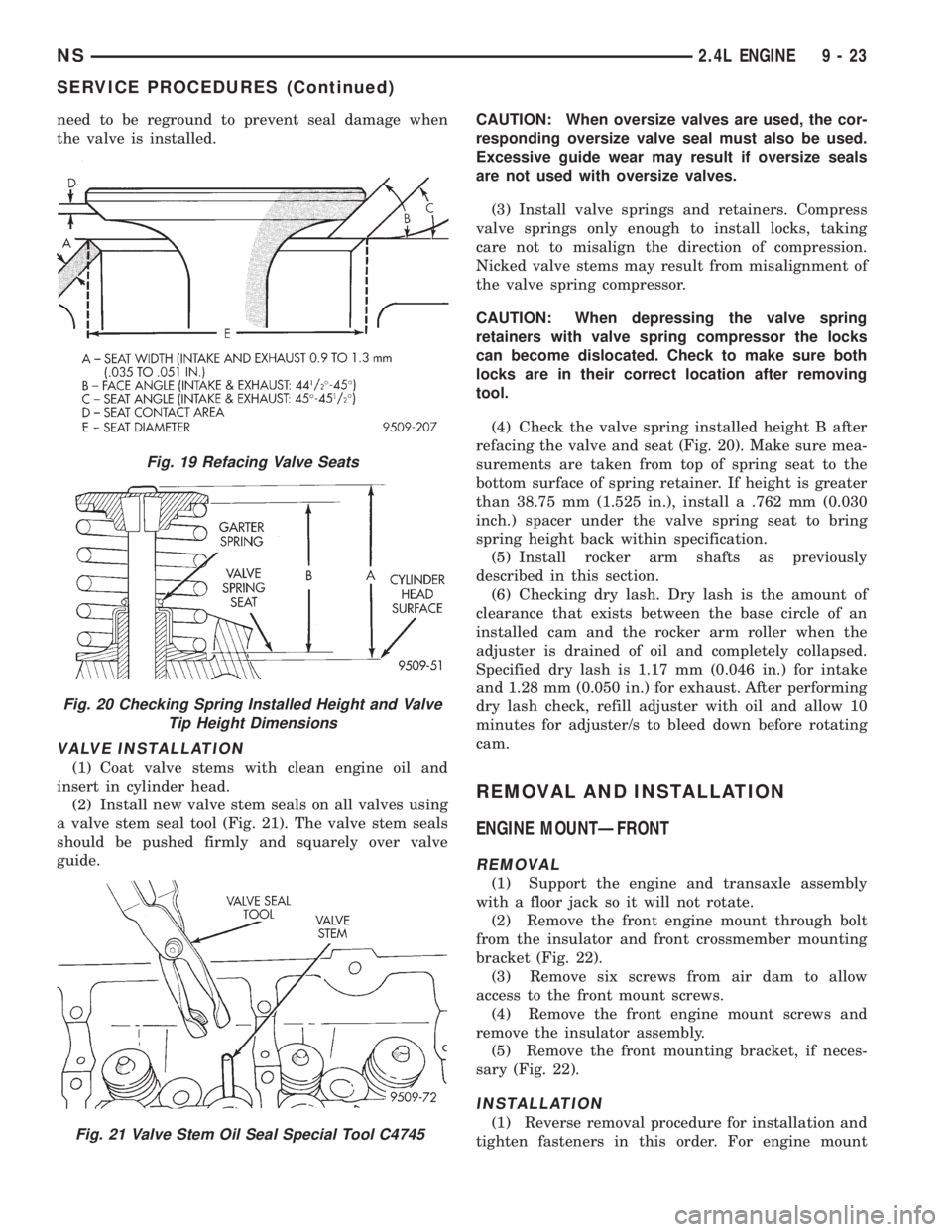
need to be reground to prevent seal damage when
the valve is installed.
VALVE INSTALLATION
(1) Coat valve stems with clean engine oil and
insert in cylinder head.
(2) Install new valve stem seals on all valves using
a valve stem seal tool (Fig. 21). The valve stem seals
should be pushed firmly and squarely over valve
guide.CAUTION: When oversize valves are used, the cor-
responding oversize valve seal must also be used.
Excessive guide wear may result if oversize seals
are not used with oversize valves.
(3) Install valve springs and retainers. Compress
valve springs only enough to install locks, taking
care not to misalign the direction of compression.
Nicked valve stems may result from misalignment of
the valve spring compressor.
CAUTION: When depressing the valve spring
retainers with valve spring compressor the locks
can become dislocated. Check to make sure both
locks are in their correct location after removing
tool.
(4) Check the valve spring installed height B after
refacing the valve and seat (Fig. 20). Make sure mea-
surements are taken from top of spring seat to the
bottom surface of spring retainer. If height is greater
than 38.75 mm (1.525 in.), install a .762 mm (0.030
inch.) spacer under the valve spring seat to bring
spring height back within specification.
(5) Install rocker arm shafts as previously
described in this section.
(6) Checking dry lash. Dry lash is the amount of
clearance that exists between the base circle of an
installed cam and the rocker arm roller when the
adjuster is drained of oil and completely collapsed.
Specified dry lash is 1.17 mm (0.046 in.) for intake
and 1.28 mm (0.050 in.) for exhaust. After performing
dry lash check, refill adjuster with oil and allow 10
minutes for adjuster/s to bleed down before rotating
cam.
REMOVAL AND INSTALLATION
ENGINE MOUNTÐFRONT
REMOVAL
(1) Support the engine and transaxle assembly
with a floor jack so it will not rotate.
(2) Remove the front engine mount through bolt
from the insulator and front crossmember mounting
bracket (Fig. 22).
(3) Remove six screws from air dam to allow
access to the front mount screws.
(4) Remove the front engine mount screws and
remove the insulator assembly.
(5) Remove the front mounting bracket, if neces-
sary (Fig. 22).
INSTALLATION
(1) Reverse removal procedure for installation and
tighten fasteners in this order. For engine mount
Fig. 19 Refacing Valve Seats
Fig. 20 Checking Spring Installed Height and Valve
Tip Height Dimensions
Fig. 21 Valve Stem Oil Seal Special Tool C4745
NS2.4L ENGINE 9 - 23
SERVICE PROCEDURES (Continued)
Page 1075 of 1938
ENGINE MOUNTÐREAR
REMOVAL
(1) Raise vehicle on hoist and remove the left
front wheel.
(2) Support the transaxle with a jack so it will not
rotate.
(3) Remove the insulator thru bolt from the
mount and rear suspension crossmember.
(4) Remove the four mount fasteners and remove
the mount.
INSTALLATION
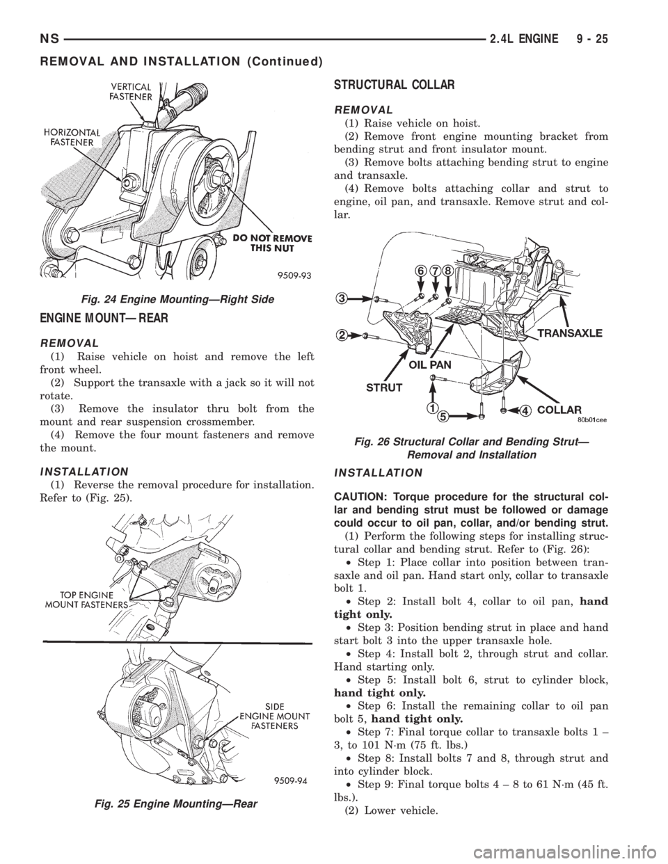
(1) Reverse the removal procedure for installation.
Refer to (Fig. 25).
STRUCTURAL COLLAR
REMOVAL
(1) Raise vehicle on hoist.
(2) Remove front engine mounting bracket from
bending strut and front insulator mount.
(3) Remove bolts attaching bending strut to engine
and transaxle.
(4) Remove bolts attaching collar and strut to
engine, oil pan, and transaxle. Remove strut and col-
lar.
INSTALLATION
CAUTION: Torque procedure for the structural col-
lar and bending strut must be followed or damage
could occur to oil pan, collar, and/or bending strut.
(1) Perform the following steps for installing struc-
tural collar and bending strut. Refer to (Fig. 26):
²Step 1: Place collar into position between tran-
saxle and oil pan. Hand start only, collar to transaxle
bolt 1.
²Step 2: Install bolt 4, collar to oil pan,hand
tight only.
²Step 3: Position bending strut in place and hand
start bolt 3 into the upper transaxle hole.
²Step 4: Install bolt 2, through strut and collar.
Hand starting only.
²Step 5: Install bolt 6, strut to cylinder block,
hand tight only.
²Step 6: Install the remaining collar to oil pan
bolt 5,hand tight only.
²Step 7: Final torque collar to transaxle bolts 1 ±
3, to 101 N´m (75 ft. lbs.)
²Step 8: Install bolts 7 and 8, through strut and
into cylinder block.
²Step 9: Final torque bolts4±8to61N´m(45ft.
lbs.).
(2) Lower vehicle.
Fig. 24 Engine MountingÐRight Side
Fig. 25 Engine MountingÐRear
Fig. 26 Structural Collar and Bending StrutÐ
Removal and Installation
NS2.4L ENGINE 9 - 25
REMOVAL AND INSTALLATION (Continued)
Page 1076 of 1938
ENGINE ASSEMBLY
REMOVAL
(1) Perform fuel pressure release procedure. Refer
to Group 14, Fuel System for procedure. Remove fuel
line to fuel rail.
(2) Disconnect battery.
(3) Remove Air cleaner and hoses.
(4) Drain cooling system. Refer to Group 7, Cooling
System for procedure.
(5) Remove upper radiator hose and remove radia-
tor fans. Refer to Group 7, Cooling System for proce-
dure.
(6) Remove lower radiator hose.
(7) Disconnect automatic transmission cooler lines
and plug, if equipped.
(8) Disconnect transmission shift linkage.
(9) Disconnect throttle body linkage.
(10) Disconnect engine wiring harness.
(11) Disconnect heater hoses.
(12) Discharge Air Conditioning System. Refer to
Group 24, Air Conditioning for procedure.
(13) Hoist vehicle and remove right inner splash
shield. Remove wheels and tires.
(14) Loosen power steering belt for pump removal.
Refer to Group 7, Cooling System for procedure.
(15) Remove axle shafts. Refer to Group 2, Suspen-
sion and Driveshafts for procedure.
(16) Disconnect exhaust pipe from manifold.
(17) Remove front and rear engine mount brackets
from the body.
(18) Remove bending braces and front engine
mount bracket. Remove transmission inspection
cover.
(19) Mark flexplate to torque converter and
remove torque converter bolts.
(20) Install front engine mount bracket.
(21) Lower vehicle.
(22) Remove power steering pump. Set pump
aside.
(23) Remove A/C lines at compressor and cap.
(24) Remove ground straps to body.
(25) Raise vehicle enough to allow engine dolly
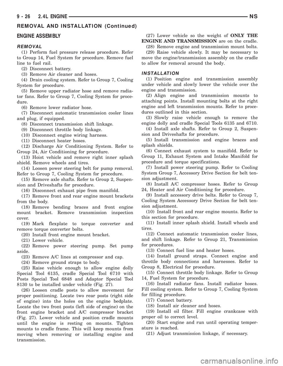
Special Tool 6135, cradle Special Tool 6710 with
Posts Special Tool 6848 and Adaptor Special Tool
8130 to be installed under vehicle (Fig. 27).
(26) Loosen cradle posts to allow movement for
proper positioning. Locate two rear posts (right side
of engine) into the holes on the engine bedplate.
Locate the two front posts (left side of engine) on the
front engine bracket and A/C compressor bracket
(Fig. 27). Lower vehicle and position cradle mounts
until the engine is resting on mounts. Tighten
mounts to cradle frame. This will keep mounts from
moving when removing or installing engine and
transmission.(27) Lower vehicle so the weight ofONLY THE
ENGINE AND TRANSMISSIONare on the cradle.
(28) Remove engine and transmission mount bolts.
(29) Raise vehicle slowly. It may be necessary to
move the engine/transmission assembly on the cradle
to allow for removal around the body.
INSTALLATION
(1) Position engine and transmission assembly
under vehicle and slowly lower the vehicle over the
engine and transmission.
(2) Align engine and transmission mounts to
attaching points. Install mounting bolts at the right
engine and left transmission mounts. Refer to proce-
dures outlined in this section.
(3) Slowly raise vehicle enough to remove the
engine dolly and cradle Special Tools 6135 and 6710.
(4) Install axle shafts. Refer to Group 2, Suspen-
sion and Driveshafts for procedure.
(5) Install transmission and engine braces and
splash shields.
(6) Connect exhaust system to manifold. Refer to
Group 11, Exhaust System and Intake Manifold for
procedure and torque specifications.
(7) Install power steering pump. Refer to Cooling
System Group 7, Accessory Drive Section for belt ten-
sion adjustment.
(8) Install A/C compressor hoses. Refer to Group
24, Heater and Air Conditioning for procedure.
(9) Install accessory drive belts. Refer to Group 7,
Cooling System Accessory Drive Section for belt ten-
sion adjustment.
(10) Install front and rear engine mounts. Refer to
this section for procedure.
(11) Install inner splash shield. Install wheels and
tires.
(12) Connect automatic transmission cooler lines,
and shift linkage. Refer to Group 21, Transmission
for procedures.
(13) Connect fuel line and heater hoses.
(14) Install ground straps. Connect engine and
throttle body connections and harnesses. Refer to
Group 8, Electrical for procedure.
(15) Connect throttle body linkage. Refer to Group
14, Fuel System for procedure.
(16) Install radiator fans. Install radiator hoses.
Fill cooling system. Refer to Group 7, Cooling System
for filling procedure.
(17) Connect battery.
(18) Install air cleaner and hoses.
(19) Install oil filter. Fill engine crankcase with
proper oil to correct level.
(20) Start engine and run until operating temper-
ature is reached.
(21) Adjust transmission linkage, if necessary.
9 - 26 2.4L ENGINENS
REMOVAL AND INSTALLATION (Continued)
Page 1078 of 1938
CYLINDER HEAD COVER
REMOVAL
(1) Remove upper intake manifold. Refer to Group
11, Exhaust System and Intake Manifold.
(2) Remove nuts attaching front and rear intake
manifold supports from cylinder head cover attaching
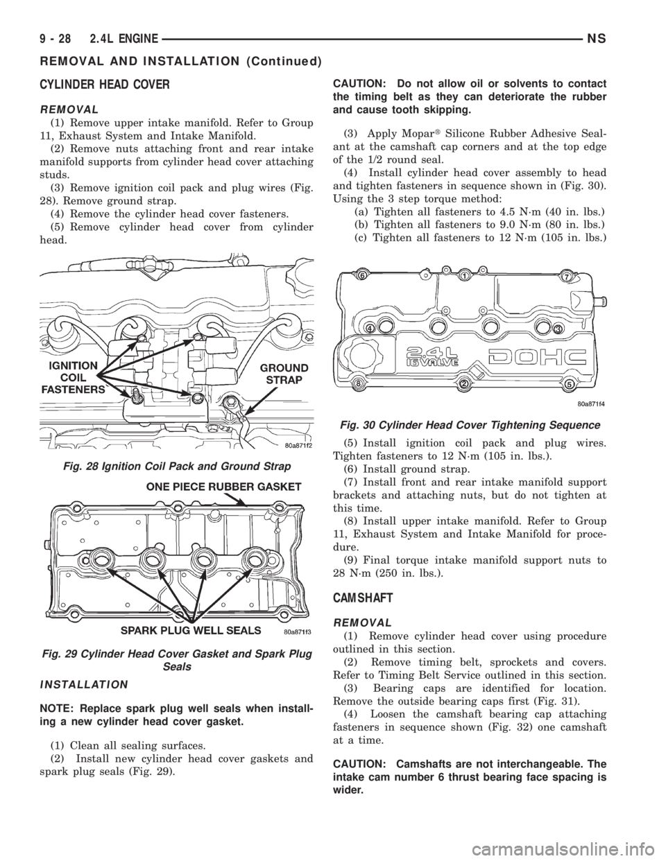
studs.
(3) Remove ignition coil pack and plug wires (Fig.
28). Remove ground strap.
(4) Remove the cylinder head cover fasteners.
(5) Remove cylinder head cover from cylinder
head.
INSTALLATION
NOTE: Replace spark plug well seals when install-
ing a new cylinder head cover gasket.
(1) Clean all sealing surfaces.
(2) Install new cylinder head cover gaskets and
spark plug seals (Fig. 29).CAUTION: Do not allow oil or solvents to contact
the timing belt as they can deteriorate the rubber
and cause tooth skipping.
(3) Apply MopartSilicone Rubber Adhesive Seal-
ant at the camshaft cap corners and at the top edge
of the 1/2 round seal.
(4) Install cylinder head cover assembly to head
and tighten fasteners in sequence shown in (Fig. 30).
Using the 3 step torque method:
(a) Tighten all fasteners to 4.5 N´m (40 in. lbs.)
(b) Tighten all fasteners to 9.0 N´m (80 in. lbs.)
(c) Tighten all fasteners to 12 N´m (105 in. lbs.)
(5) Install ignition coil pack and plug wires.
Tighten fasteners to 12 N´m (105 in. lbs.).
(6) Install ground strap.
(7) Install front and rear intake manifold support
brackets and attaching nuts, but do not tighten at
this time.
(8) Install upper intake manifold. Refer to Group
11, Exhaust System and Intake Manifold for proce-
dure.
(9) Final torque intake manifold support nuts to
28 N´m (250 in. lbs.).
CAMSHAFT
REMOVAL
(1) Remove cylinder head cover using procedure
outlined in this section.
(2) Remove timing belt, sprockets and covers.
Refer to Timing Belt Service outlined in this section.
(3) Bearing caps are identified for location.
Remove the outside bearing caps first (Fig. 31).
(4) Loosen the camshaft bearing cap attaching
fasteners in sequence shown (Fig. 32) one camshaft
at a time.
CAUTION: Camshafts are not interchangeable. The
intake cam number 6 thrust bearing face spacing is
wider.
Fig. 28 Ignition Coil Pack and Ground Strap
Fig. 29 Cylinder Head Cover Gasket and Spark Plug
Seals
Fig. 30 Cylinder Head Cover Tightening Sequence
9 - 28 2.4L ENGINENS
REMOVAL AND INSTALLATION (Continued)