1996 CHRYSLER VOYAGER engine oil
[x] Cancel search: engine oilPage 1059 of 1938
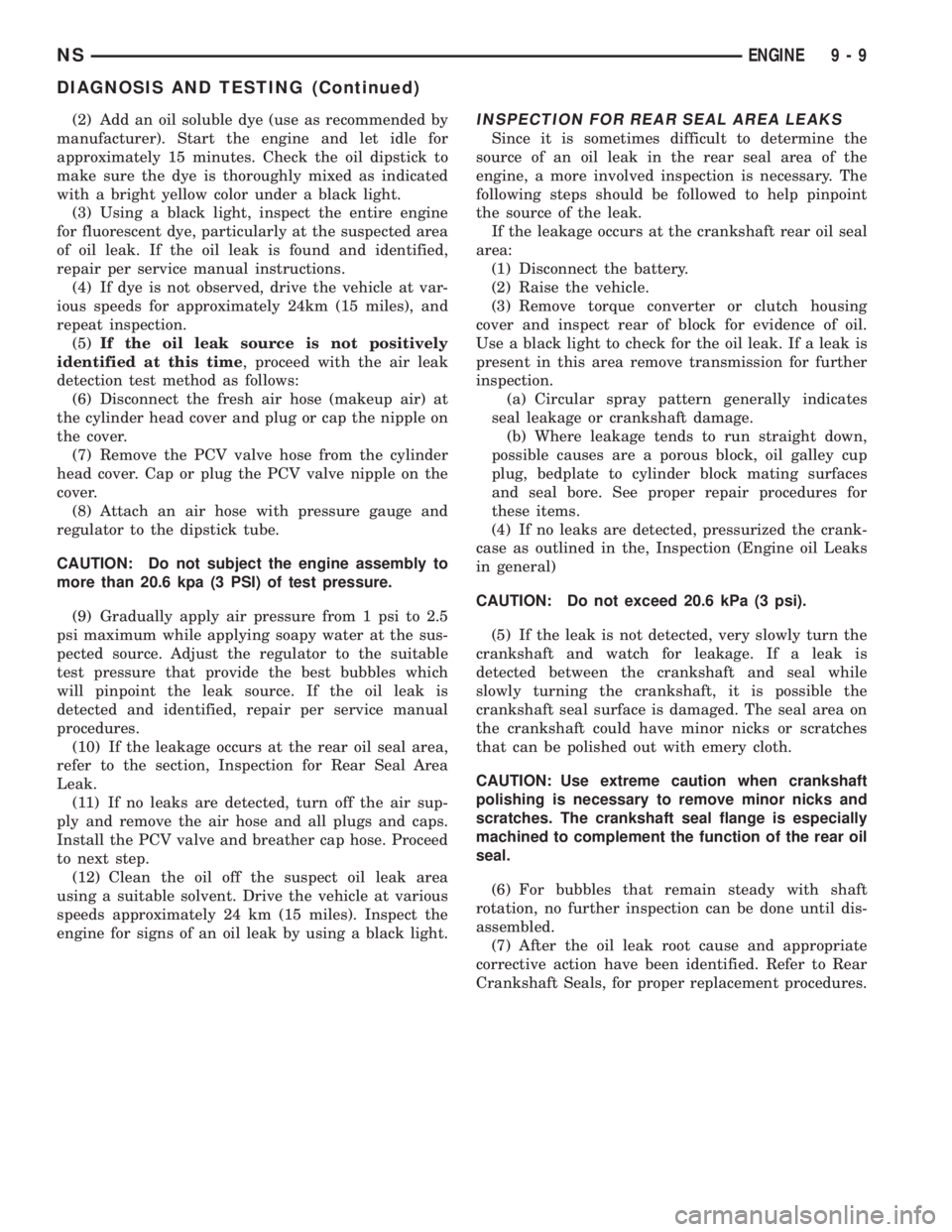
(2) Add an oil soluble dye (use as recommended by
manufacturer). Start the engine and let idle for
approximately 15 minutes. Check the oil dipstick to
make sure the dye is thoroughly mixed as indicated
with a bright yellow color under a black light.
(3) Using a black light, inspect the entire engine
for fluorescent dye, particularly at the suspected area
of oil leak. If the oil leak is found and identified,
repair per service manual instructions.
(4) If dye is not observed, drive the vehicle at var-
ious speeds for approximately 24km (15 miles), and
repeat inspection.
(5)If the oil leak source is not positively
identified at this time, proceed with the air leak
detection test method as follows:
(6) Disconnect the fresh air hose (makeup air) at
the cylinder head cover and plug or cap the nipple on
the cover.
(7) Remove the PCV valve hose from the cylinder
head cover. Cap or plug the PCV valve nipple on the
cover.
(8) Attach an air hose with pressure gauge and
regulator to the dipstick tube.
CAUTION: Do not subject the engine assembly to
more than 20.6 kpa (3 PSI) of test pressure.
(9) Gradually apply air pressure from 1 psi to 2.5
psi maximum while applying soapy water at the sus-
pected source. Adjust the regulator to the suitable
test pressure that provide the best bubbles which
will pinpoint the leak source. If the oil leak is
detected and identified, repair per service manual
procedures.
(10) If the leakage occurs at the rear oil seal area,
refer to the section, Inspection for Rear Seal Area
Leak.
(11) If no leaks are detected, turn off the air sup-
ply and remove the air hose and all plugs and caps.
Install the PCV valve and breather cap hose. Proceed
to next step.
(12) Clean the oil off the suspect oil leak area
using a suitable solvent. Drive the vehicle at various
speeds approximately 24 km (15 miles). Inspect the
engine for signs of an oil leak by using a black light.INSPECTION FOR REAR SEAL AREA LEAKS
Since it is sometimes difficult to determine the
source of an oil leak in the rear seal area of the
engine, a more involved inspection is necessary. The
following steps should be followed to help pinpoint
the source of the leak.
If the leakage occurs at the crankshaft rear oil seal
area:
(1) Disconnect the battery.
(2) Raise the vehicle.
(3) Remove torque converter or clutch housing
cover and inspect rear of block for evidence of oil.
Use a black light to check for the oil leak. If a leak is
present in this area remove transmission for further
inspection.
(a) Circular spray pattern generally indicates
seal leakage or crankshaft damage.
(b) Where leakage tends to run straight down,
possible causes are a porous block, oil galley cup
plug, bedplate to cylinder block mating surfaces
and seal bore. See proper repair procedures for
these items.
(4) If no leaks are detected, pressurized the crank-
case as outlined in the, Inspection (Engine oil Leaks
in general)
CAUTION: Do not exceed 20.6 kPa (3 psi).
(5) If the leak is not detected, very slowly turn the
crankshaft and watch for leakage. If a leak is
detected between the crankshaft and seal while
slowly turning the crankshaft, it is possible the
crankshaft seal surface is damaged. The seal area on
the crankshaft could have minor nicks or scratches
that can be polished out with emery cloth.
CAUTION: Use extreme caution when crankshaft
polishing is necessary to remove minor nicks and
scratches. The crankshaft seal flange is especially
machined to complement the function of the rear oil
seal.
(6) For bubbles that remain steady with shaft
rotation, no further inspection can be done until dis-
assembled.
(7) After the oil leak root cause and appropriate
corrective action have been identified. Refer to Rear
Crankshaft Seals, for proper replacement procedures.
NSENGINE 9 - 9
DIAGNOSIS AND TESTING (Continued)
Page 1060 of 1938
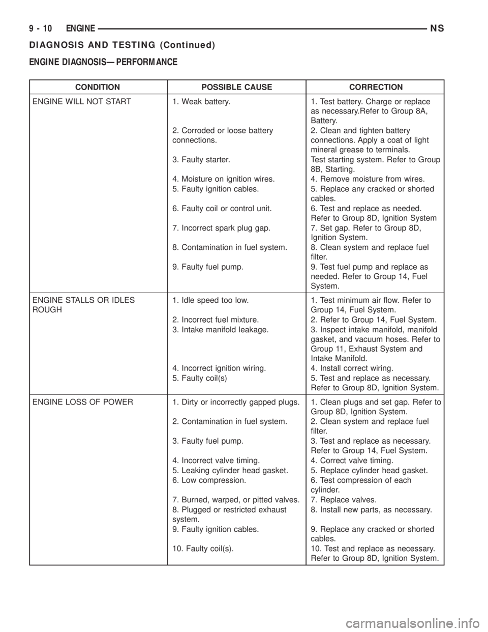
ENGINE DIAGNOSISÐPERFORMANCE
CONDITION POSSIBLE CAUSE CORRECTION
ENGINE WILL NOT START 1. Weak battery. 1. Test battery. Charge or replace
as necessary.Refer to Group 8A,
Battery.
2. Corroded or loose battery
connections.2. Clean and tighten battery
connections. Apply a coat of light
mineral grease to terminals.
3. Faulty starter. Test starting system. Refer to Group
8B, Starting.
4. Moisture on ignition wires. 4. Remove moisture from wires.
5. Faulty ignition cables. 5. Replace any cracked or shorted
cables.
6. Faulty coil or control unit. 6. Test and replace as needed.
Refer to Group 8D, Ignition System
7. Incorrect spark plug gap. 7. Set gap. Refer to Group 8D,
Ignition System.
8. Contamination in fuel system. 8. Clean system and replace fuel
filter.
9. Faulty fuel pump. 9. Test fuel pump and replace as
needed. Refer to Group 14, Fuel
System.
ENGINE STALLS OR IDLES
ROUGH1. Idle speed too low. 1. Test minimum air flow. Refer to
Group 14, Fuel System.
2. Incorrect fuel mixture. 2. Refer to Group 14, Fuel System.
3. Intake manifold leakage. 3. Inspect intake manifold, manifold
gasket, and vacuum hoses. Refer to
Group 11, Exhaust System and
Intake Manifold.
4. Incorrect ignition wiring. 4. Install correct wiring.
5. Faulty coil(s) 5. Test and replace as necessary.
Refer to Group 8D, Ignition System.
ENGINE LOSS OF POWER 1. Dirty or incorrectly gapped plugs. 1. Clean plugs and set gap. Refer to
Group 8D, Ignition System.
2. Contamination in fuel system. 2. Clean system and replace fuel
filter.
3. Faulty fuel pump. 3. Test and replace as necessary.
Refer to Group 14, Fuel System.
4. Incorrect valve timing. 4. Correct valve timing.
5. Leaking cylinder head gasket. 5. Replace cylinder head gasket.
6. Low compression. 6. Test compression of each
cylinder.
7. Burned, warped, or pitted valves. 7. Replace valves.
8. Plugged or restricted exhaust
system.8. Install new parts, as necessary.
9. Faulty ignition cables. 9. Replace any cracked or shorted
cables.
10. Faulty coil(s). 10. Test and replace as necessary.
Refer to Group 8D, Ignition System.
9 - 10 ENGINENS
DIAGNOSIS AND TESTING (Continued)
Page 1061 of 1938
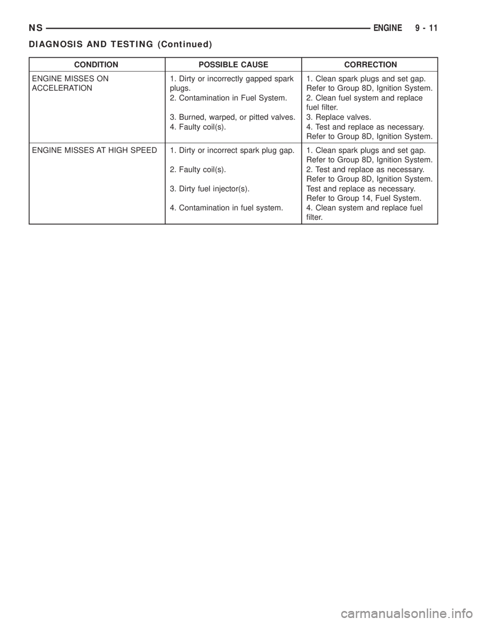
CONDITION POSSIBLE CAUSE CORRECTION
ENGINE MISSES ON
ACCELERATION1. Dirty or incorrectly gapped spark
plugs.1. Clean spark plugs and set gap.
Refer to Group 8D, Ignition System.
2. Contamination in Fuel System. 2. Clean fuel system and replace
fuel filter.
3. Burned, warped, or pitted valves. 3. Replace valves.
4. Faulty coil(s). 4. Test and replace as necessary.
Refer to Group 8D, Ignition System.
ENGINE MISSES AT HIGH SPEED 1. Dirty or incorrect spark plug gap. 1. Clean spark plugs and set gap.
Refer to Group 8D, Ignition System.
2. Faulty coil(s). 2. Test and replace as necessary.
Refer to Group 8D, Ignition System.
3. Dirty fuel injector(s). Test and replace as necessary.
Refer to Group 14, Fuel System.
4. Contamination in fuel system. 4. Clean system and replace fuel
filter.
NSENGINE 9 - 11
DIAGNOSIS AND TESTING (Continued)
Page 1062 of 1938
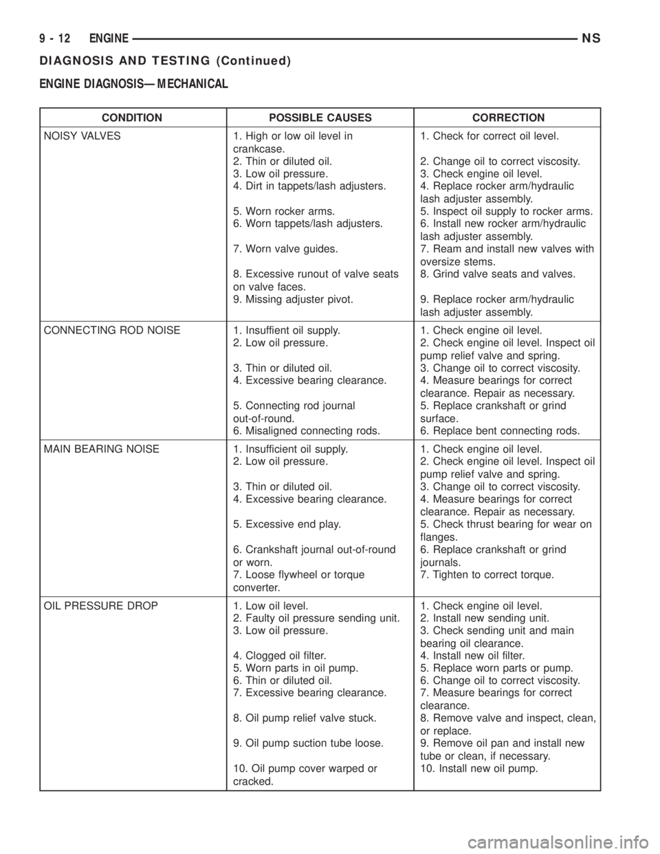
ENGINE DIAGNOSISÐMECHANICAL
CONDITION POSSIBLE CAUSES CORRECTION
NOISY VALVES 1. High or low oil level in
crankcase.1. Check for correct oil level.
2. Thin or diluted oil. 2. Change oil to correct viscosity.
3. Low oil pressure. 3. Check engine oil level.
4. Dirt in tappets/lash adjusters. 4. Replace rocker arm/hydraulic
lash adjuster assembly.
5. Worn rocker arms. 5. Inspect oil supply to rocker arms.
6. Worn tappets/lash adjusters. 6. Install new rocker arm/hydraulic
lash adjuster assembly.
7. Worn valve guides. 7. Ream and install new valves with
oversize stems.
8. Excessive runout of valve seats
on valve faces.8. Grind valve seats and valves.
9. Missing adjuster pivot. 9. Replace rocker arm/hydraulic
lash adjuster assembly.
CONNECTING ROD NOISE 1. Insuffient oil supply. 1. Check engine oil level.
2. Low oil pressure. 2. Check engine oil level. Inspect oil
pump relief valve and spring.
3. Thin or diluted oil. 3. Change oil to correct viscosity.
4. Excessive bearing clearance. 4. Measure bearings for correct
clearance. Repair as necessary.
5. Connecting rod journal
out-of-round.5. Replace crankshaft or grind
surface.
6. Misaligned connecting rods. 6. Replace bent connecting rods.
MAIN BEARING NOISE 1. Insufficient oil supply. 1. Check engine oil level.
2. Low oil pressure. 2. Check engine oil level. Inspect oil
pump relief valve and spring.
3. Thin or diluted oil. 3. Change oil to correct viscosity.
4. Excessive bearing clearance. 4. Measure bearings for correct
clearance. Repair as necessary.
5. Excessive end play. 5. Check thrust bearing for wear on
flanges.
6. Crankshaft journal out-of-round
or worn.6. Replace crankshaft or grind
journals.
7. Loose flywheel or torque
converter.7. Tighten to correct torque.
OIL PRESSURE DROP 1. Low oil level. 1. Check engine oil level.
2. Faulty oil pressure sending unit. 2. Install new sending unit.
3. Low oil pressure. 3. Check sending unit and main
bearing oil clearance.
4. Clogged oil filter. 4. Install new oil filter.
5. Worn parts in oil pump. 5. Replace worn parts or pump.
6. Thin or diluted oil. 6. Change oil to correct viscosity.
7. Excessive bearing clearance. 7. Measure bearings for correct
clearance.
8. Oil pump relief valve stuck. 8. Remove valve and inspect, clean,
or replace.
9. Oil pump suction tube loose. 9. Remove oil pan and install new
tube or clean, if necessary.
10. Oil pump cover warped or
cracked.10. Install new oil pump.
9 - 12 ENGINENS
DIAGNOSIS AND TESTING (Continued)
Page 1063 of 1938
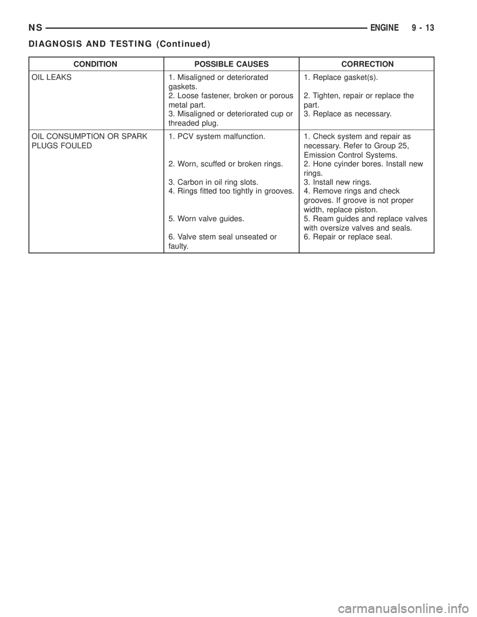
CONDITION POSSIBLE CAUSES CORRECTION
OIL LEAKS 1. Misaligned or deteriorated
gaskets.1. Replace gasket(s).
2. Loose fastener, broken or porous
metal part.2. Tighten, repair or replace the
part.
3. Misaligned or deteriorated cup or
threaded plug.3. Replace as necessary.
OIL CONSUMPTION OR SPARK
PLUGS FOULED1. PCV system malfunction. 1. Check system and repair as
necessary. Refer to Group 25,
Emission Control Systems.
2. Worn, scuffed or broken rings. 2. Hone cyinder bores. Install new
rings.
3. Carbon in oil ring slots. 3. Install new rings.
4. Rings fitted too tightly in grooves. 4. Remove rings and check
grooves. If groove is not proper
width, replace piston.
5. Worn valve guides. 5. Ream guides and replace valves
with oversize valves and seals.
6. Valve stem seal unseated or
faulty.6. Repair or replace seal.
NSENGINE 9 - 13
DIAGNOSIS AND TESTING (Continued)
Page 1064 of 1938
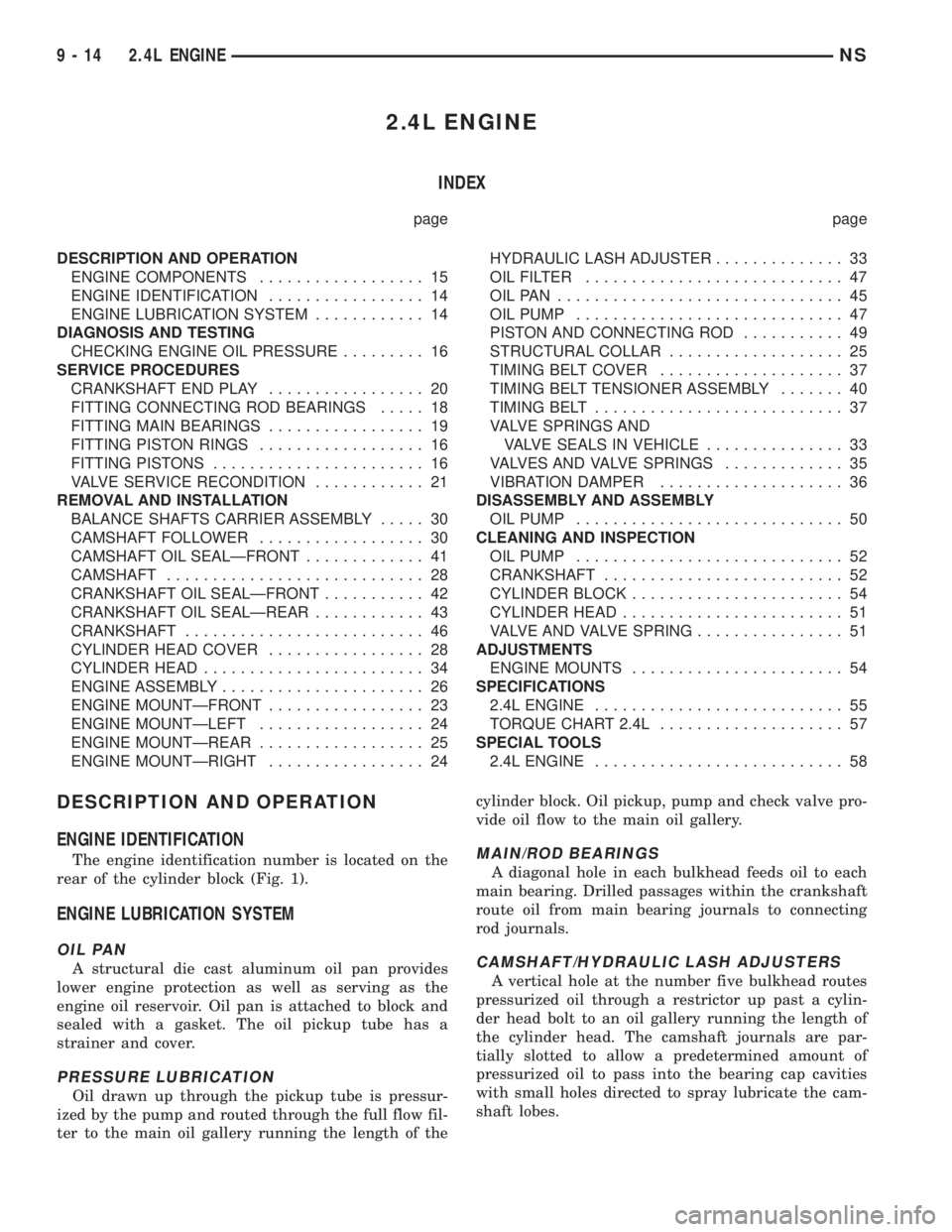
2.4L ENGINE
INDEX
page page
DESCRIPTION AND OPERATION
ENGINE COMPONENTS.................. 15
ENGINE IDENTIFICATION................. 14
ENGINE LUBRICATION SYSTEM............ 14
DIAGNOSIS AND TESTING
CHECKING ENGINE OIL PRESSURE......... 16
SERVICE PROCEDURES
CRANKSHAFT END PLAY................. 20
FITTING CONNECTING ROD BEARINGS..... 18
FITTING MAIN BEARINGS................. 19
FITTING PISTON RINGS.................. 16
FITTING PISTONS....................... 16
VALVE SERVICE RECONDITION............ 21
REMOVAL AND INSTALLATION
BALANCE SHAFTS CARRIER ASSEMBLY..... 30
CAMSHAFT FOLLOWER.................. 30
CAMSHAFT OIL SEALÐFRONT............. 41
CAMSHAFT............................ 28
CRANKSHAFT OIL SEALÐFRONT........... 42
CRANKSHAFT OIL SEALÐREAR............ 43
CRANKSHAFT.......................... 46
CYLINDER HEAD COVER................. 28
CYLINDER HEAD........................ 34
ENGINE ASSEMBLY...................... 26
ENGINE MOUNTÐFRONT................. 23
ENGINE MOUNTÐLEFT.................. 24
ENGINE MOUNTÐREAR.................. 25
ENGINE MOUNTÐRIGHT................. 24HYDRAULIC LASH ADJUSTER.............. 33
OILFILTER ............................ 47
OILPAN ............................... 45
OIL PUMP............................. 47
PISTON AND CONNECTING ROD........... 49
STRUCTURAL COLLAR................... 25
TIMING BELT COVER.................... 37
TIMING BELT TENSIONER ASSEMBLY....... 40
TIMING BELT........................... 37
VALVE SPRINGS AND
VALVE SEALS IN VEHICLE............... 33
VALVES AND VALVE SPRINGS............. 35
VIBRATION DAMPER.................... 36
DISASSEMBLY AND ASSEMBLY
OIL PUMP............................. 50
CLEANING AND INSPECTION
OIL PUMP............................. 52
CRANKSHAFT.......................... 52
CYLINDER BLOCK....................... 54
CYLINDER HEAD........................ 51
VALVE AND VALVE SPRING................ 51
ADJUSTMENTS
ENGINE MOUNTS....................... 54
SPECIFICATIONS
2.4L ENGINE........................... 55
TORQUE CHART 2.4L.................... 57
SPECIAL TOOLS
2.4L ENGINE........................... 58
DESCRIPTION AND OPERATION
ENGINE IDENTIFICATION
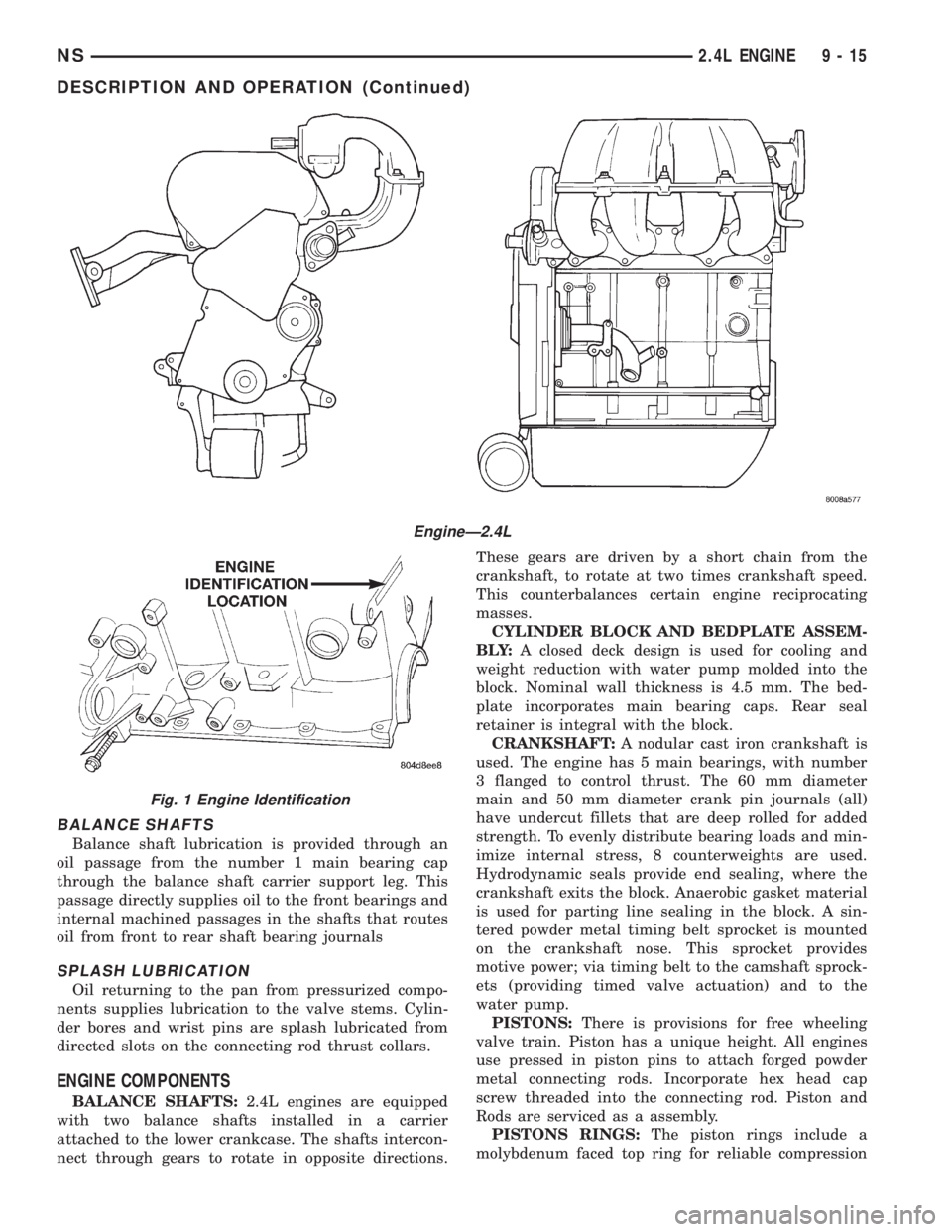
The engine identification number is located on the
rear of the cylinder block (Fig. 1).
ENGINE LUBRICATION SYSTEM
OIL PAN
A structural die cast aluminum oil pan provides
lower engine protection as well as serving as the
engine oil reservoir. Oil pan is attached to block and
sealed with a gasket. The oil pickup tube has a
strainer and cover.
PRESSURE LUBRICATION
Oil drawn up through the pickup tube is pressur-
ized by the pump and routed through the full flow fil-
ter to the main oil gallery running the length of thecylinder block. Oil pickup, pump and check valve pro-
vide oil flow to the main oil gallery.
MAIN/ROD BEARINGS
A diagonal hole in each bulkhead feeds oil to each
main bearing. Drilled passages within the crankshaft
route oil from main bearing journals to connecting
rod journals.
CAMSHAFT/HYDRAULIC LASH ADJUSTERS
A vertical hole at the number five bulkhead routes
pressurized oil through a restrictor up past a cylin-
der head bolt to an oil gallery running the length of
the cylinder head. The camshaft journals are par-
tially slotted to allow a predetermined amount of
pressurized oil to pass into the bearing cap cavities
with small holes directed to spray lubricate the cam-
shaft lobes.
9 - 14 2.4L ENGINENS
Page 1065 of 1938
BALANCE SHAFTS
Balance shaft lubrication is provided through an
oil passage from the number 1 main bearing cap
through the balance shaft carrier support leg. This
passage directly supplies oil to the front bearings and
internal machined passages in the shafts that routes
oil from front to rear shaft bearing journals
SPLASH LUBRICATION
Oil returning to the pan from pressurized compo-
nents supplies lubrication to the valve stems. Cylin-
der bores and wrist pins are splash lubricated from
directed slots on the connecting rod thrust collars.
ENGINE COMPONENTS
BALANCE SHAFTS:2.4L engines are equipped
with two balance shafts installed in a carrier
attached to the lower crankcase. The shafts intercon-
nect through gears to rotate in opposite directions.These gears are driven by a short chain from the
crankshaft, to rotate at two times crankshaft speed.
This counterbalances certain engine reciprocating
masses.
CYLINDER BLOCK AND BEDPLATE ASSEM-
B LY:A closed deck design is used for cooling and
weight reduction with water pump molded into the
block. Nominal wall thickness is 4.5 mm. The bed-
plate incorporates main bearing caps. Rear seal
retainer is integral with the block.
CRANKSHAFT:A nodular cast iron crankshaft is
used. The engine has 5 main bearings, with number
3 flanged to control thrust. The 60 mm diameter
main and 50 mm diameter crank pin journals (all)
have undercut fillets that are deep rolled for added
strength. To evenly distribute bearing loads and min-
imize internal stress, 8 counterweights are used.
Hydrodynamic seals provide end sealing, where the
crankshaft exits the block. Anaerobic gasket material
is used for parting line sealing in the block. A sin-
tered powder metal timing belt sprocket is mounted
on the crankshaft nose. This sprocket provides
motive power; via timing belt to the camshaft sprock-
ets (providing timed valve actuation) and to the
water pump.
PISTONS:There is provisions for free wheeling
valve train. Piston has a unique height. All engines
use pressed in piston pins to attach forged powder
metal connecting rods. Incorporate hex head cap
screw threaded into the connecting rod. Piston and
Rods are serviced as a assembly.
PISTONS RINGS:The piston rings include a
molybdenum faced top ring for reliable compression
EngineÐ2.4L
Fig. 1 Engine Identification
NS2.4L ENGINE 9 - 15
DESCRIPTION AND OPERATION (Continued)
Page 1066 of 1938
sealing and a chrome plated taper faced intermediate
ring for additional cylinder pressure control. There
are also standard oil control rings.
CYLINDER HEAD:Features a Dual Over Head
Camshaft (DOHC) 4 valves per cylinder cross flow
design. The valves are arranged in two inline banks,
with the ports of the bank of two intake valves per
cylinder facing toward the radiator side of engine
and ports of the bank of two exhaust valves per cyl-
inder facing toward the dash panel. Incorporates
powder metal valve guides and seats. Integral oil gal-
leys within the cylinder head supplies oil to the
hydraulic lash adjusters, camshaft and valve mecha-
nisms.
CAMSHAFTS:The nodular iron camshafts have
six bearing journals and 2 cam lobes per cylinder.
Flanges at the rear journals control camshaft end
play. Provision for cam position sensor is located on
the intake camshaft at the rear of cylinder head. A
hydrodynamic oil seal is used for oil control at the
front of the camshaft.
VALVES:4 valves per cylinder are actuated by
roller cam followers which pivot on stationary
hydraulic lash adjusters. All valves have 6 mm diam-
eter chrome plated valve stems. The valve sizes are
34.8 mm (1.370 inch.) diameter intake valves and
30.5 mm (1.20 inch.) diameter exhaust valves. Viton
rubber valve stem seals are integral with the spring
seats. Valve springs, spring retainers, and locks are
conventional.
INTAKE MANIFOLD:The intake manifold is a
two piece aluminum casting, attached to the cylinder
head with ten screws. This long branch fan design
enhances low and midspeed torque, while minimizing
undesirable inlet noise.
EXHAUST MANIFOLD:The exhaust manifold is
made of cast iron for strength and high tempera-
tures.
ENGINE LUBRICATION:Refer to Group 0
Lubrication and Maintenance for recommended oil to
be used in various engine application. System is full
flow filtration, pressure feed type. The oil pump is
mounted in the front engine cover and driven by the
crankshaft. Pressurized oil is then routed through
the main oil gallery, running the length of the cylin-
der block, supplying main and rod bearings with fur-
ther routing. Pistons are lubricated from rod bearing
throw off and lubricating slots on the connecting rod
assemblies. Camshaft and valve mechanisms are
lubricated from a full length cylinder head oil gallery
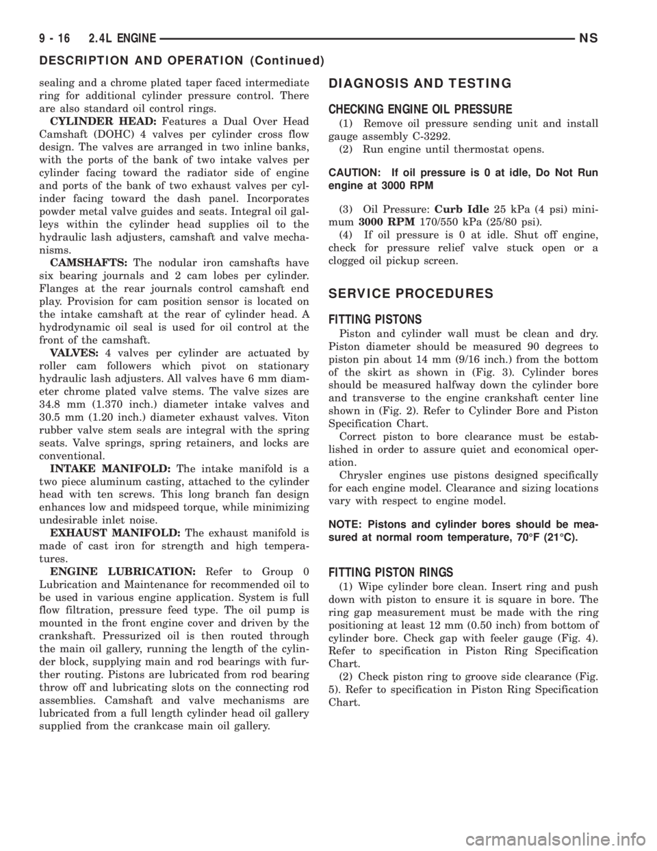
supplied from the crankcase main oil gallery.DIAGNOSIS AND TESTING
CHECKING ENGINE OIL PRESSURE
(1) Remove oil pressure sending unit and install
gauge assembly C-3292.
(2) Run engine until thermostat opens.
CAUTION: If oil pressure is 0 at idle, Do Not Run
engine at 3000 RPM
(3) Oil Pressure:Curb Idle25 kPa (4 psi) mini-
mum3000 RPM170/550 kPa (25/80 psi).
(4) If oil pressure is 0 at idle. Shut off engine,
check for pressure relief valve stuck open or a
clogged oil pickup screen.
SERVICE PROCEDURES
FITTING PISTONS
Piston and cylinder wall must be clean and dry.
Piston diameter should be measured 90 degrees to
piston pin about 14 mm (9/16 inch.) from the bottom
of the skirt as shown in (Fig. 3). Cylinder bores
should be measured halfway down the cylinder bore
and transverse to the engine crankshaft center line
shown in (Fig. 2). Refer to Cylinder Bore and Piston
Specification Chart.
Correct piston to bore clearance must be estab-
lished in order to assure quiet and economical oper-
ation.
Chrysler engines use pistons designed specifically
for each engine model. Clearance and sizing locations
vary with respect to engine model.
NOTE: Pistons and cylinder bores should be mea-
sured at normal room temperature, 70ÉF (21ÉC).
FITTING PISTON RINGS
(1) Wipe cylinder bore clean. Insert ring and push
down with piston to ensure it is square in bore. The
ring gap measurement must be made with the ring
positioning at least 12 mm (0.50 inch) from bottom of
cylinder bore. Check gap with feeler gauge (Fig. 4).
Refer to specification in Piston Ring Specification
Chart.
(2) Check piston ring to groove side clearance (Fig.
5). Refer to specification in Piston Ring Specification
Chart.
9 - 16 2.4L ENGINENS
DESCRIPTION AND OPERATION (Continued)