1996 CHRYSLER VOYAGER instrument cluster
[x] Cancel search: instrument clusterPage 1467 of 1938
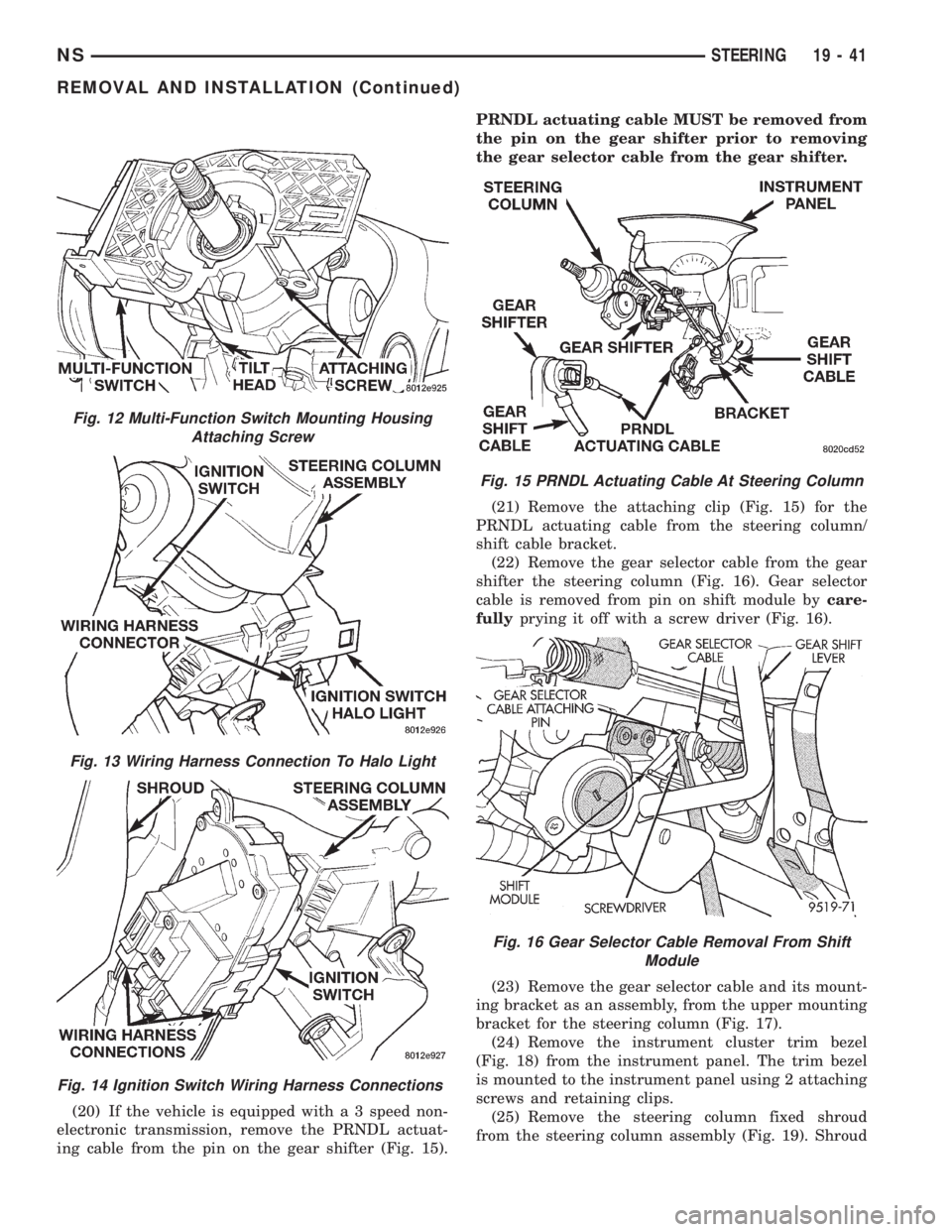
(20) If the vehicle is equipped with a 3 speed non-
electronic transmission, remove the PRNDL actuat-
ing cable from the pin on the gear shifter (Fig. 15).PRNDL actuating cable MUST be removed from
the pin on the gear shifter prior to removing
the gear selector cable from the gear shifter.
(21) Remove the attaching clip (Fig. 15) for the
PRNDL actuating cable from the steering column/
shift cable bracket.
(22) Remove the gear selector cable from the gear
shifter the steering column (Fig. 16). Gear selector
cable is removed from pin on shift module bycare-
fullyprying it off with a screw driver (Fig. 16).
(23) Remove the gear selector cable and its mount-
ing bracket as an assembly, from the upper mounting
bracket for the steering column (Fig. 17).
(24) Remove the instrument cluster trim bezel
(Fig. 18) from the instrument panel. The trim bezel
is mounted to the instrument panel using 2 attaching
screws and retaining clips.
(25) Remove the steering column fixed shroud
from the steering column assembly (Fig. 19). Shroud
Fig. 12 Multi-Function Switch Mounting Housing
Attaching Screw
Fig. 13 Wiring Harness Connection To Halo Light
Fig. 14 Ignition Switch Wiring Harness Connections
Fig. 15 PRNDL Actuating Cable At Steering Column
Fig. 16 Gear Selector Cable Removal From Shift
Module
NSSTEERING 19 - 41
REMOVAL AND INSTALLATION (Continued)
Page 1468 of 1938
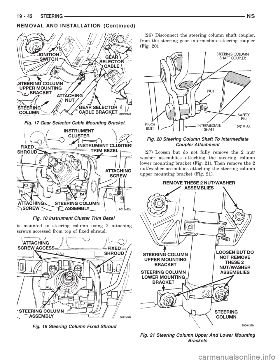
is mounted to steering column using 2 attaching
screws accessed from top of fixed shroud.(26) Disconnect the steering column shaft coupler,
from the steering gear intermediate steering coupler
(Fig. 20).
(27) Loosen but do not fully remove the 2 nut/
washer assemblies attaching the steering column
lower mounting bracket (Fig. 21). Then remove the 2
nut/washer assemblies attaching the steering column
upper mounting bracket (Fig. 21).
Fig. 17 Gear Selector Cable Mounting Bracket
Fig. 18 Instrument Cluster Trim Bezel
Fig. 19 Steering Column Fixed Shroud
Fig. 20 Steering Column Shaft To Intermediate
Coupler Attachment
Fig. 21 Steering Column Upper And Lower Mounting
Brackets
19 - 42 STEERINGNS
REMOVAL AND INSTALLATION (Continued)
Page 1469 of 1938
(28) Remove steering column assembly from vehi-
cle. Use care to avoid damage to paint or interior
trim.
INSTALL
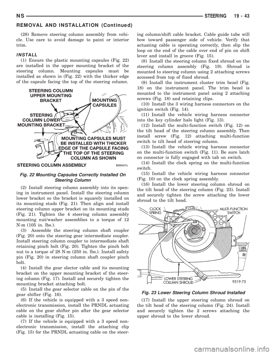
(1) Ensure the plastic mounting capsules (Fig. 22)
are installed in the upper mounting bracket of the
steering column. Mounting capsules must be
installed as shown in (Fig. 22) with the thicker edge
of the capsule facing the top of the steering column.
(2) Install steering column assembly into its open-
ing in instrument panel. Install the steering column
lower bracket so the bracket is squarely installed on
its mounting studs (Fig. 21). Then align and install
steering column upper bracket on its mounting studs
(Fig. 21). Tighten the 4 steering column assembly
mounting nut/washer assemblies to a torque of 12
N´m (105 in. lbs.).
(3) Assemble the steering column shaft coupler
(Fig. 20) onto the steering gear intermediate coupler.
Install steering column coupler to intermediate shaft
retaining pinch bolt (Fig. 20). Tighten the pinch bolt
nut to a torque of 28 N´m (250 in. lbs.). Install safety
pin (Fig. 20) in steering column shaft coupler pinch
bolt.
(4) Install the gear slector cable and its mounting
bracket on the upper mounting bracket of the steer-
ing column (Fig. 17). Install and securely tighten the
mounting bracket attaching bolt.
(5) Install the gear selector cable on the pin of the
gear shifter (Fig. 16).
(6) If the vehicle is equipped with a 3 speed non-
electronic transmission, install the PRNDL actuating
cable on the gear shifter pin after the gear selector
cable is installing (Fig. 15).
(7) If the vehicle is equipped with a 3 speed non-
electronic transmission, install the attaching clip
(Fig. 15) for the PRNDL actuating cable on the steer-ing column/shift cable bracket. Cable guide tube will
bow toward passenger side of vehicle. Verify that
actuating cable is operating correctly, then slip the
loop on the end of the cable over end of pin on shift
lever and install in groove (Fig. 15).
(8) Install the steering column fixed shroud on the
steering column assembly (Fig. 19). Shroud is
mounted to steering column using 2 attaching screws
accessed from top of fixed shroud.
(9) Install the instrument cluster trim bezel (Fig.
18) on the instrument panel. The trim bezel is
mounted to the instrument panel using 2 attaching
screws (Fig. 18) and retaining clips.
(10) Install the 3 wiring harness connectors on the
ignition switch (Fig. 14).
(11) Install the vehicle wiring harness connector
into the key cylinder halo light (Fig. 13).
(12) Install the multi-function switch (Fig. 12) on
the tilt head of the steering column assembly. Then
install screw (Fig. 12) attaching multi-function
switch to tilt head of steering column.
(13) Install the vehicle wiring harness connector
on the multi-function switch (Fig. 11). Be sure latch
on connector is fully engaged with tab on switch.
(14) Install the clock spring on the multi-function
switch.
(15) Install the vehicle wiring harness connector
(Fig. 10) on the clock spring assembly.
(16) Install the lower steering column shroud on
the tilt head of the steering column (Fig. 23). Install
and securely tighten the screw attaching the lower
shroud to the tilt head.
(17) Install the upper steering column shroud on
the tilt head of the steering column (Fig. 24). Install
and securely tighten the 2 screws attaching the
upper shroud to the lower shroud.
Fig. 22 Mounting Capsules Correctly Installed On
Steering Column
Fig. 23 Lower Steering Column Shroud Installed
NSSTEERING 19 - 43
REMOVAL AND INSTALLATION (Continued)
Page 1548 of 1938
TORQUE MANAGEMENT
Most 41TE transaxles utilize torque management.
Torque management is a unique function of the Pow-
ertrain Control Module (PCM). The PCM receives
output signals from the Transmission Control Module
(TCM) and many various engine sensors. The PCM
evaluates these signals and decides if it is necessary
to decrease the output of the engine's torque. This
reduction in torque does not interfere with the nor-
mal operation of the vehicle. This reduction in torque
will prolong the life of the drivetrain components.
Torque reduction is not noticeable in normal driving
functions. The torque reduction function shuts off
above 16 MPH.
ON-BOARD DIAGNOSTICS
This vehicle utilizes a diagnostic system called
OBDII. The powertrain control module communicates
with the Transmission Control Module. Whenever
the transaxle sets a fault in the Transmission Con-
trol Module (dependent on which fault is set), the
powertrain control module will turn on a MIL (Mal-
function Indicator Lamp) on the instrument cluster.
By reading the code in the powertrain control module
it will tell you where the fault occurred. If the fault
occurred in the transaxle, the controller will read a
CODE 45.For further information regarding OBDII,
refer to Group 25, Emission Systems.
These controls provide comprehensive, on-board
transaxle diagnostics. The information available can
aid in transaxle diagnosis. For example, apply ele-
ment buildup rate indicates solenoid performance.
Also included are self diagnostic functions. Self diag-
nostics allow the technician to test the condition of
the electronic controls. The Transmission Control
Module continuously monitors its critical functions. It
also records any malfunctions, and the number of
engine starts since the last malfunction. This allows
the technician to use the information in the event of
a customer complaint.
TRANSMISSION CONTROL MODULE
Do not interchange Transmission Control Modules
with previous year transmission control modules. If a
same year TCM is being used from a different vehi-
cle, the following procedures must be performed:
²Quick Learn Procedure
²Electronic Pinion Factor Procedure
The Transmission Control Module is located on the
right inner fender panel, in the engine compartment.
It is held in place by four mounting screws.NOTE: If the Transmission Control Module has
been replaced, the following procedures must be
performed:
²Quick Learn Procedure: This procedure will
allow the transmission control module to learn the
characteristics of the vehicle.
²Electronic Pinion Factor Procedure: This proce-
dure will reprogram the TCM to compensate for dif-
ferent tire sizes and final drive ratios.
GEARSHIFT AND PARKING LOCK CONTROLS
The transaxle is controlled by a lever type gear-
shift incorporated within the steering column. The
control has six selector lever positions: P (park), R
(reverse), N (neutral), and D (drive), 2 (second), and
1 (first). The parking lock is applied by moving the
selector lever past a gate to the P position.Do not
apply the parking lock until the vehicle has
stopped; otherwise, a severe ratchet noise will
occur.
TRANSMISSION RANGE SENSOR
The 41TE transaxle is equipped with a transmis-
sion range sensor that is located on top of the valve
body. This sensor will allow for accurate transmission
gear position measurement.
To service the transmission range sensor (TRS),
you must remove the valve body. For repair proce-
dures, refer to the Removal and Installation section
within this group.
Also located within the TRS is a transmission tem-
perature sensor. This sensor is used to measure the
transmission fluid sump temperature. The transmis-
sion temperature sensor is serviced with the TRS as
a unit.
SHIFT POSITION INDICATOR
The shifter position indicator is located in the
instrument cluster. The shifter position indicator out-
lines with a box the gear position the transaxle man-
ual valve lever is in.
The transmission range sensor (located on the
valvebody) sends a signal to the TCM on the position
of the transaxle manual valve lever. The TCM
receives the switch signal and processes the data.
The TCM sends the Shift Lever Position (SLP) infor-
mation to the BCM via the CCD bus. The BCM then
outlines with a box the appropriate shifter position
indicator in the instrument cluster.
To replace the shifter position indicator, refer to
Group 8E, Instrument Panel And Gauges.
21 - 74 TRANSAXLE AND POWER TRANSFER UNITNS
DESCRIPTION AND OPERATION (Continued)
Page 1552 of 1938
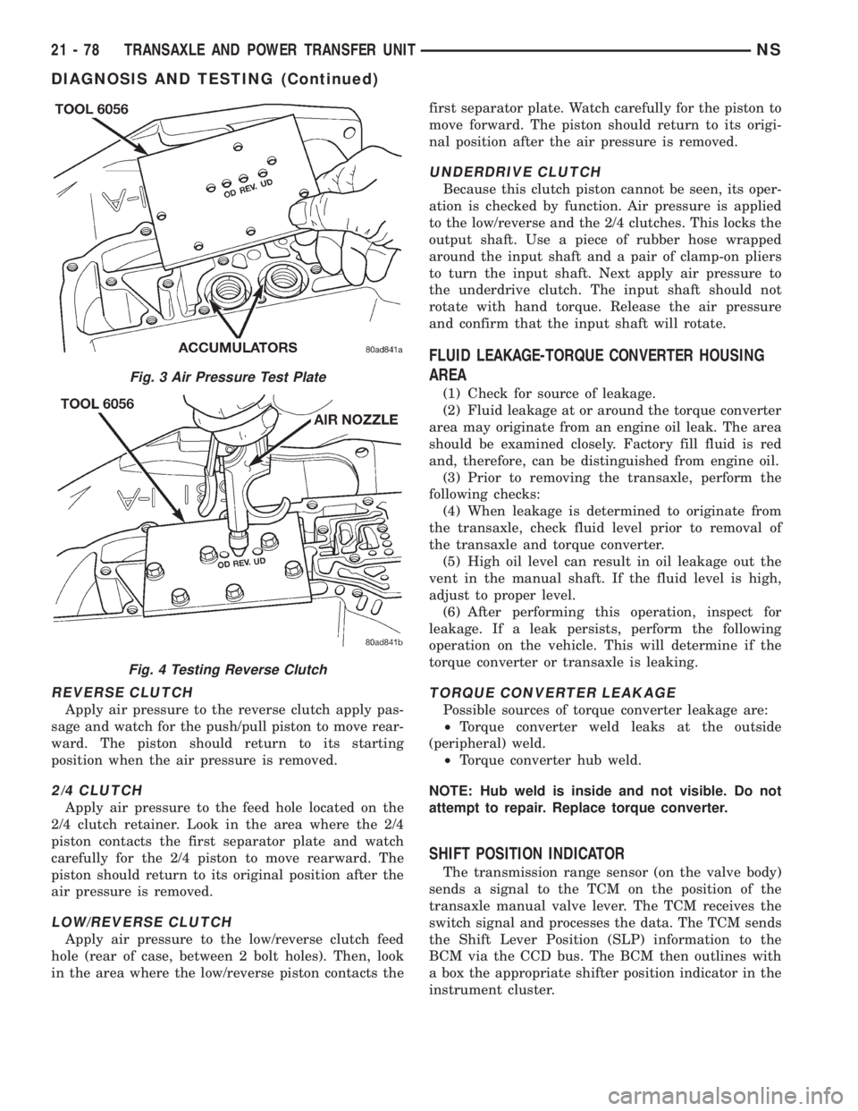
REVERSE CLUTCH
Apply air pressure to the reverse clutch apply pas-
sage and watch for the push/pull piston to move rear-
ward. The piston should return to its starting
position when the air pressure is removed.
2/4 CLUTCH
Apply air pressure to the feed hole located on the
2/4 clutch retainer. Look in the area where the 2/4
piston contacts the first separator plate and watch
carefully for the 2/4 piston to move rearward. The
piston should return to its original position after the
air pressure is removed.
LOW/REVERSE CLUTCH
Apply air pressure to the low/reverse clutch feed
hole (rear of case, between 2 bolt holes). Then, look
in the area where the low/reverse piston contacts thefirst separator plate. Watch carefully for the piston to
move forward. The piston should return to its origi-
nal position after the air pressure is removed.
UNDERDRIVE CLUTCH
Because this clutch piston cannot be seen, its oper-
ation is checked by function. Air pressure is applied
to the low/reverse and the 2/4 clutches. This locks the
output shaft. Use a piece of rubber hose wrapped
around the input shaft and a pair of clamp-on pliers
to turn the input shaft. Next apply air pressure to
the underdrive clutch. The input shaft should not
rotate with hand torque. Release the air pressure
and confirm that the input shaft will rotate.
FLUID LEAKAGE-TORQUE CONVERTER HOUSING
AREA
(1) Check for source of leakage.
(2) Fluid leakage at or around the torque converter
area may originate from an engine oil leak. The area
should be examined closely. Factory fill fluid is red
and, therefore, can be distinguished from engine oil.
(3) Prior to removing the transaxle, perform the
following checks:
(4) When leakage is determined to originate from
the transaxle, check fluid level prior to removal of
the transaxle and torque converter.
(5) High oil level can result in oil leakage out the
vent in the manual shaft. If the fluid level is high,
adjust to proper level.
(6) After performing this operation, inspect for
leakage. If a leak persists, perform the following
operation on the vehicle. This will determine if the
torque converter or transaxle is leaking.
TORQUE CONVERTER LEAKAGE
Possible sources of torque converter leakage are:
²Torque converter weld leaks at the outside
(peripheral) weld.
²Torque converter hub weld.
NOTE: Hub weld is inside and not visible. Do not
attempt to repair. Replace torque converter.
SHIFT POSITION INDICATOR
The transmission range sensor (on the valve body)
sends a signal to the TCM on the position of the
transaxle manual valve lever. The TCM receives the
switch signal and processes the data. The TCM sends
the Shift Lever Position (SLP) information to the
BCM via the CCD bus. The BCM then outlines with
a box the appropriate shifter position indicator in the
instrument cluster.
Fig. 3 Air Pressure Test Plate
Fig. 4 Testing Reverse Clutch
21 - 78 TRANSAXLE AND POWER TRANSFER UNITNS
DIAGNOSIS AND TESTING (Continued)
Page 1553 of 1938
If a problem arises with the shifter position indica-
tor, consult the following chart for diagnostic infor-
mation. If the malfunction cannot be corrected using
the chart, consult the proper diagnostic manual.
To replace the shifter position indicator, refer to
Group 8E, Instrument Panel And Gauges.SERVICE PROCEDURES
FLUID AND FILTER CHANGE
When the factory fill fluid is changed, only fluids
labeled MOPARtATF PLUS 3 (Automatic Transmis-
sion fluid) Type 7176 should be used.
If the transaxle is disassembled for any reason, the
fluid and filter should be changed.
30,000 MILE TRANSAXLE OIL CHANGE
When a vehicle attains 30,000 miles on its odome-
ter it is recommended that the transaxle oil be
changed. To change the oil, use the procedure that
follows:
It is recommended that a transaxle fluid exchanger
(ATF 2000+ or equivalent) be used to replace the
used fluid in the transaxle. If a fluid exchanger is not
available use a fluid suction pump (Vaculayor equiv-
alent) to draw the fluid out of the dipstick tube. If a
fluid suction pump is not available remove the oil
pan and drain the fluid.
CAUTION: Chrysler Corporation does not recom-
mend using any fluid exchanger that introduces
additives into the transaxle.
TRANSAXLE FLUID EXCHANGER METHOD
(1) To perform the transaxle fluid exchange, the
transaxle must be at operating temperature. Drive
the vehicle till it reaches full operating temperature.
(2) Verify that the fill tank on the transaxle fluid
exchanger (ATF 2000+ or equivalent) is clean and
dry.
(3) Fill the tank to the recommended fill capacity
with Mopar ATF Plus 3 Type 7176.
(4) Hookup the vehicle to the machine following
the manufacturers instructions. Perform the
exchange procedure following the instructions pro-
vided with the machine.
(5) Once machine has completed the fluid
exchange. Check the fluid level and condition and fill
to proper level with Mopar ATF Plus 3 Type 7176.
NOTE: Verify that the transaxle cooler lines are
tightened to proper specifications. Cooler line
torque specification is 2 N´m (18 in. lbs.).
CONDITION POSSIBLE CAUSE
ALL PRND3L DISPLAY
LIGHTS9ON9IN P&N
GEAR POSITIONS1.Check wiring and
connectors
2. Faulty trans. range
sensor
3. Faulty manual lever
ALL DISPLAY LIGHTS
9ON9IN ALL GEAR
POSITIONS1. Check wiring &
connectors
2. Faulty trans. range
sensor
3. Faulty manual lever
4. CCD communication
malfunction
5. Check oil level
ALL DISPLAY LIGHTS
9OFF91. Normal transient
condition between P&R
and R&N gear positions
2. Check shift lever
linkage
3. Body controller
malfunction
4. Check wiring and
connectors
5. Faulty cluster
ALL DISPLAY LIGHTS
9OFF9ACCOMPANIED
BY A9NO BUS9
MESSAGE1. CCD communication
malfunction
DISPLAY LIGHTS OUT
OF SEQUENCE WITH
SHIFT LEVER1. Check wiring and
connectors
2. Faulty trans. range
sensor
3. Faulty manual lever
4. CCD communication
malfunction
NSTRANSAXLE AND POWER TRANSFER UNIT 21 - 79
DIAGNOSIS AND TESTING (Continued)
Page 1906 of 1938
cranking. Whenever the Powertrain Control Module
(PCM) sets a Diagnostic Trouble Code (DTC) that
affects vehicle emissions, it illuminates the MIL. If a
problem is detected, the PCM sends a message over
the CCD Bus to the instrument cluster to illuminate
the lamp. The PCM illuminates the MIL only for
DTC's that affect vehicle emissions. The MIL stays
on continuously when the PCM has entered a
Limp-In mode or identified a failed emission compo-
nent or system. The MIL remains on until the DTC
is erased. Refer to the Diagnostic Trouble Code
charts in this group for emission related codes.
Also, the MIL either flashes or illuminates contin-
uously when the PCM detects active engine misfire.
Refer to Misfire Monitoring in this section.
Additionally, the PCM may reset (turn off) the MIL
when one of the following occur:
²PCM does not detect the malfunction for 3 con-
secutive trips (except misfire and fuel system moni-
tors).
²PCM does not detect a malfunction while per-
forming three successive engine misfire or fuel sys-
tem tests. The PCM performs these tests while the
engine is operating within6375 RPM of and within
10 % of the load of the operating condition at which
the malfunction was first detected.
STATE DISPLAY TEST MODE
The switch inputs to the Powertrain Control Mod-
ule (PCM) have two recognized states; HIGH and
LOW. For this reason, the PCM cannot recognize the
difference between a selected switch position versus
an open circuit, a short circuit, or a defective switch.
If the State Display screen shows the change from
HIGH to LOW or LOW to HIGH, assume the entire
switch circuit to the PCM functions properly. From
the state display screen, access either State Display
Inputs and Outputs or State Display Sensors.
STATE DISPLAY INPUTS AND OUTPUTS
Connect the DRB scan tool to the data link connec-
tor and access the State Display screen. Then access
Inputs and Outputs. The following list contains the
PCM system functions accessible through the Inputs
and Outputs screen.
Park/Neutral Switch
Speed Control Resume
Brake Switch
Speed Control On/Off
Speed Control Set
S/C Vent Solenoid
Actual S/C Vent Sol.
S/C Vacuum Solenoid
Actual S/C Vacuum Sol.
S/C Cancel
S/C Last Cutout
S/C Working Status
S/C Denied Status
A/C Clutch Relay
Actual A/C Clutch Relay
EGR Solenoid
Actual EGR Sol.
Automatic Shutdown Relay
Actual Automatic Shutdown Relay
Automatic Shutdown Relay Sense
Radiator Fan Control Module
Actual Radiator Fan Control Module
Duty Cycle EVAP Purge Solenoid
Actual EVAP Purge Sol.
Torque Converter Clutch Solenoid
Power Steering Switch
Closed Loop State
Current CMP Edge
Current CKP State
Current Sync State
Fuel Pump Relay
Actual Fuel Pump Relay
Ignition Sense (A21)
Malfunction Lamp
Limp-in Reason
STATE DISPLAY SENSORS
Connect the DRB scan tool to the vehicle and
access the State Display screen. Then access Sensor
Display. The following list contains the PCM system
functions accessible through the Sensor Display
screen.
Battery Temperature
Engine Coolant Temperature
Engine Coolant Temp Sensor
Throttle Position Volts
Minimum Throttle
Knock Sensor Volts
Battery Voltage
MAP Sensor Reading
Idle Air Control Motor Position
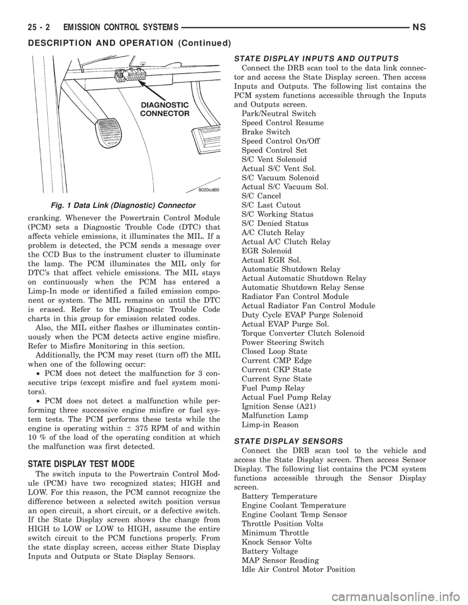
Fig. 1 Data Link (Diagnostic) Connector
25 - 2 EMISSION CONTROL SYSTEMSNS
DESCRIPTION AND OPERATION (Continued)