1996 CHRYSLER VOYAGER coolant temperature
[x] Cancel search: coolant temperaturePage 1411 of 1938
FUEL INJECTION SYSTEMÐ2.5L DIESEL ENGINE
INDEX
page page
GENERAL INFORMATION
INTRODUCTION....................... 43
DESCRIPTION AND OPERATION
AIR CONDITIONING (A/C) CONTROLSÐ
PCM INPUTS........................ 47
AIR CONDITIONING RELAYÐPCM OUTPUT . . 48
BATTERY VOLTAGEÐPCM INPUT.......... 45
BOOST PRESSURE SENSOR............. 45
BRAKE SWITCHÐPCM INPUT............. 47
DATA LINK CONNECTORÐ
PCM INPUT AND OUTPUT.............. 47
DIESEL PCM RELAYÐPCM INPUT......... 48
ENGINE COOLANT GAUGEÐPCM OUTPUT . . 48
ENGINE COOLANT TEMPERATURE SENSORÐ
PCM INPUT......................... 46
ENGINE OIL PRESSURE GAUGEÐ
PCM OUTPUT........................ 48
ENGINE SPEED SENSORÐPCM INPUT..... 46
EXHAUST GAS RECIRCULATION (EGR)
SOLENOIDÐPCM OUTPUT............. 50
FIVE VOLT POWERÐPCM OUTPUT........ 48
FUEL INJECTOR SENSORÐGROUND...... 46
FUEL TIMING SOLENOIDÐPCM OUTPUT.... 48
GLOW PLUG LAMPÐPCM OUTPUT........ 48
GLOW PLUG RELAYÐPCM OUTPUT....... 49
GLOW PLUGS......................... 49
IGNITION CIRCUIT SENSEÐPCM INPUT.... 45
NEEDLE MOVEMENT OR INSTRUMENTED
FIRST INJECTORÐPCM INPUT.......... 45
POWER GROUND...................... 45
POWERTRAIN CONTROL MODULE (PCM) . . . 44
SENSOR RETURNÐPCM INPUT (ANALOG
GROUND)........................... 45SIGNAL GROUNDÐPCM INPUT........... 45
SPEED CONTROLÐPCM INPUTS.......... 48
SPEED CONTROLÐPCM OUTPUTS........ 48
START SIGNALÐPCM INPUT............. 45
TACHOMETERÐPCM OUTPUT............ 49
VEHICLE SPEED SENSORÐPCM INPUT.... 47
VEHICLE THEFT ALARM................. 45
DIAGNOSIS AND TESTING
BOOST PRESSURE SENSOR............. 53
DIAGNOSTIC TROUBLE CODES........... 53
DIESEL DIAGNOSTICS.................. 50
DIESEL PCM RELAY TEST............... 50
ENGINE COOLANT TEMPERATURE
SENSOR TEST....................... 50
ENGINE SPEED SENSOR TEST........... 50
GLOW PLUG RELAY TEST............... 51
GLOW PLUG TEST..................... 51
RELAYSÐOPERATION/TESTING........... 52
VEHICLE SPEED SENSOR TEST........... 53
REMOVAL AND INSTALLATION
A/C CLUTCH RELAY.................... 53
DIESEL PCM RELAY.................... 53
ENGINE COOLANT TEMPERATURE
SENSOR............................ 54
ENGINE SPEED SENSOR................ 53
GLOW PLUG RELAY.................... 55
GLOW PLUGS......................... 54
POWERTRAIN CONTROL MODULE (PCM) . . . 55
VEHICLE SPEED SENSOR............... 55
SPECIFICATIONS
GLOW PLUG CURRENT DRAW............ 56
TORQUE CHARTÐ2.5L DIESEL............ 57
GENERAL INFORMATION
INTRODUCTION
This section will cover components either regulated
or controlled by the Powertrain Control Module
(PCM). The fuel heater relay, fuel heater and fuel
gauge are not operated by the PCM. These compo-
nents are controlled by the ignition (key) switch. All
other fuel system electrical components necessary to
operate the engine are controlled or regulated by the
PCM. Refer to the following PCM description for
more information.
Certain fuel system component failures may cause
a no start, or prevent the engine from running. It is
important to know that the PCM has a featurewhere, if possible, it will ignore the failed sensor, set
a code related to the sensor, and operate the engine
in a ªLimp Homeº mode. When the PCM is operating
in a ªLimp Homeº mode, the Diesel Glow Plug lamp
on the instrument panel will be constantly illumi-
nated, and the engine will most likely have a notice-
able loss of performance. An example of this would be
an Accelerator Pedal Position Sensor failure, and in
that situation, the engine would run at a constant
1100 RPM, regardless of the actual position of the
pedal. This is the most extreme of the three ªLimp
Homeº modes.
In addition to indicating that the glow plugs are
hot enough to start combustion, the Glow Plug Lamp
is also used in the diagnosis of the PCM, and when
NS/GSFUEL SYSTEMÐ2.5L DIESEL ENGINE/2.0L GAS ENGINE 14 - 43
Page 1412 of 1938
illuminated constantly, it usually indicates a problem
has been detected somewhere within the fuel system.
The DRBIII scan tool is the best method for commu-
nicating with the PCM to diagnose faults within the
system.
DESCRIPTION AND OPERATION
POWERTRAIN CONTROL MODULE (PCM)
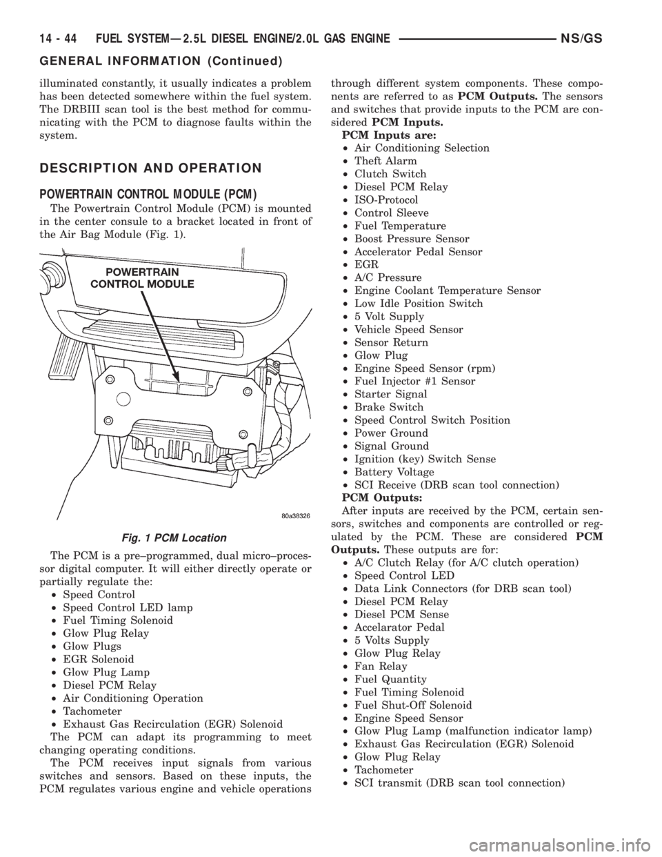
The Powertrain Control Module (PCM) is mounted
in the center consule to a bracket located in front of
the Air Bag Module (Fig. 1).
The PCM is a pre±programmed, dual micro±proces-
sor digital computer. It will either directly operate or
partially regulate the:
²Speed Control
²Speed Control LED lamp
²Fuel Timing Solenoid
²Glow Plug Relay
²Glow Plugs
²EGR Solenoid
²Glow Plug Lamp
²Diesel PCM Relay
²Air Conditioning Operation
²Tachometer
²Exhaust Gas Recirculation (EGR) Solenoid
The PCM can adapt its programming to meet
changing operating conditions.
The PCM receives input signals from various
switches and sensors. Based on these inputs, the
PCM regulates various engine and vehicle operationsthrough different system components. These compo-
nents are referred to asPCM Outputs.The sensors
and switches that provide inputs to the PCM are con-
sideredPCM Inputs.
PCM Inputs are:
²Air Conditioning Selection
²Theft Alarm
²Clutch Switch
²Diesel PCM Relay
²ISO-Protocol
²Control Sleeve
²Fuel Temperature
²Boost Pressure Sensor
²Accelerator Pedal Sensor
²EGR
²A/C Pressure
²Engine Coolant Temperature Sensor
²Low Idle Position Switch
²5 Volt Supply
²Vehicle Speed Sensor
²Sensor Return
²Glow Plug
²Engine Speed Sensor (rpm)
²Fuel Injector #1 Sensor
²Starter Signal
²Brake Switch
²Speed Control Switch Position
²Power Ground
²Signal Ground
²Ignition (key) Switch Sense
²Battery Voltage
²SCI Receive (DRB scan tool connection)
PCM Outputs:
After inputs are received by the PCM, certain sen-
sors, switches and components are controlled or reg-
ulated by the PCM. These are consideredPCM
Outputs.These outputs are for:
²A/C Clutch Relay (for A/C clutch operation)
²Speed Control LED
²Data Link Connectors (for DRB scan tool)
²Diesel PCM Relay
²Diesel PCM Sense
²Accelarator Pedal
²5 Volts Supply
²Glow Plug Relay
²Fan Relay
²Fuel Quantity
²Fuel Timing Solenoid
²Fuel Shut-Off Solenoid
²Engine Speed Sensor
²Glow Plug Lamp (malfunction indicator lamp)
²Exhaust Gas Recirculation (EGR) Solenoid
²Glow Plug Relay
²Tachometer
²SCI transmit (DRB scan tool connection)
Fig. 1 PCM Location
14 - 44 FUEL SYSTEMÐ2.5L DIESEL ENGINE/2.0L GAS ENGINENS/GS
GENERAL INFORMATION (Continued)
Page 1414 of 1938
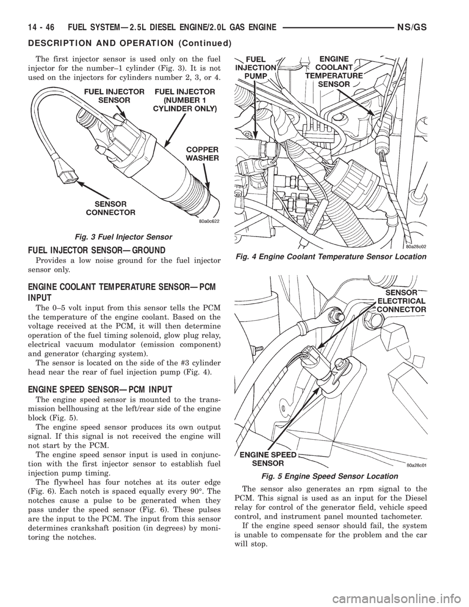
The first injector sensor is used only on the fuel
injector for the number±1 cylinder (Fig. 3). It is not
used on the injectors for cylinders number 2, 3, or 4.
FUEL INJECTOR SENSORÐGROUND
Provides a low noise ground for the fuel injector
sensor only.
ENGINE COOLANT TEMPERATURE SENSORÐPCM
INPUT
The 0±5 volt input from this sensor tells the PCM
the temperature of the engine coolant. Based on the
voltage received at the PCM, it will then determine
operation of the fuel timing solenoid, glow plug relay,
electrical vacuum modulator (emission component)
and generator (charging system).
The sensor is located on the side of the #3 cylinder
head near the rear of fuel injection pump (Fig. 4).
ENGINE SPEED SENSORÐPCM INPUT
The engine speed sensor is mounted to the trans-
mission bellhousing at the left/rear side of the engine
block (Fig. 5).
The engine speed sensor produces its own output
signal. If this signal is not received the engine will
not start by the PCM.
The engine speed sensor input is used in conjunc-
tion with the first injector sensor to establish fuel
injection pump timing.
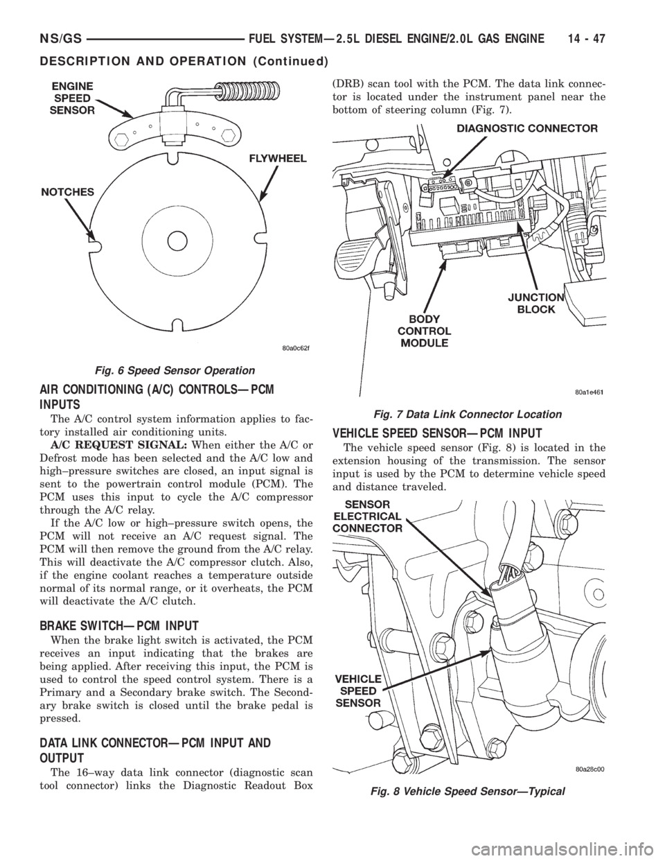
The flywheel has four notches at its outer edge
(Fig. 6). Each notch is spaced equally every 90É. The
notches cause a pulse to be generated when they
pass under the speed sensor (Fig. 6). These pulses
are the input to the PCM. The input from this sensor
determines crankshaft position (in degrees) by moni-
toring the notches.The sensor also generates an rpm signal to the
PCM. This signal is used as an input for the Diesel
relay for control of the generator field, vehicle speed
control, and instrument panel mounted tachometer.
If the engine speed sensor should fail, the system
is unable to compensate for the problem and the car
will stop.
Fig. 3 Fuel Injector Sensor
Fig. 4 Engine Coolant Temperature Sensor Location
Fig. 5 Engine Speed Sensor Location
14 - 46 FUEL SYSTEMÐ2.5L DIESEL ENGINE/2.0L GAS ENGINENS/GS
DESCRIPTION AND OPERATION (Continued)
Page 1415 of 1938
AIR CONDITIONING (A/C) CONTROLSÐPCM
INPUTS
The A/C control system information applies to fac-
tory installed air conditioning units.
A/C REQUEST SIGNAL:When either the A/C or
Defrost mode has been selected and the A/C low and
high±pressure switches are closed, an input signal is
sent to the powertrain control module (PCM). The
PCM uses this input to cycle the A/C compressor
through the A/C relay.
If the A/C low or high±pressure switch opens, the
PCM will not receive an A/C request signal. The
PCM will then remove the ground from the A/C relay.
This will deactivate the A/C compressor clutch. Also,
if the engine coolant reaches a temperature outside
normal of its normal range, or it overheats, the PCM
will deactivate the A/C clutch.
BRAKE SWITCHÐPCM INPUT
When the brake light switch is activated, the PCM
receives an input indicating that the brakes are
being applied. After receiving this input, the PCM is
used to control the speed control system. There is a
Primary and a Secondary brake switch. The Second-
ary brake switch is closed until the brake pedal is
pressed.
DATA LINK CONNECTORÐPCM INPUT AND
OUTPUT
The 16±way data link connector (diagnostic scan
tool connector) links the Diagnostic Readout Box(DRB) scan tool with the PCM. The data link connec-
tor is located under the instrument panel near the
bottom of steering column (Fig. 7).
VEHICLE SPEED SENSORÐPCM INPUT
The vehicle speed sensor (Fig. 8) is located in the
extension housing of the transmission. The sensor
input is used by the PCM to determine vehicle speed
and distance traveled.
Fig. 6 Speed Sensor Operation
Fig. 7 Data Link Connector Location
Fig. 8 Vehicle Speed SensorÐTypical
NS/GSFUEL SYSTEMÐ2.5L DIESEL ENGINE/2.0L GAS ENGINE 14 - 47
DESCRIPTION AND OPERATION (Continued)
Page 1417 of 1938
±cycle, the lower the advance. The lower the duty-
±cycle, the more advanced the fuel timing.
The duty±cycle is determined by the PCM from
inputs it receives from the fuel injector sensor and
engine speed sensor.
TACHOMETERÐPCM OUTPUT
The PCM supplies engine rpm values to the Body
Controller that then supplies the instrument cluster
mounted tachometer (if equipped). Refer to Group 8E
for tachometer information.
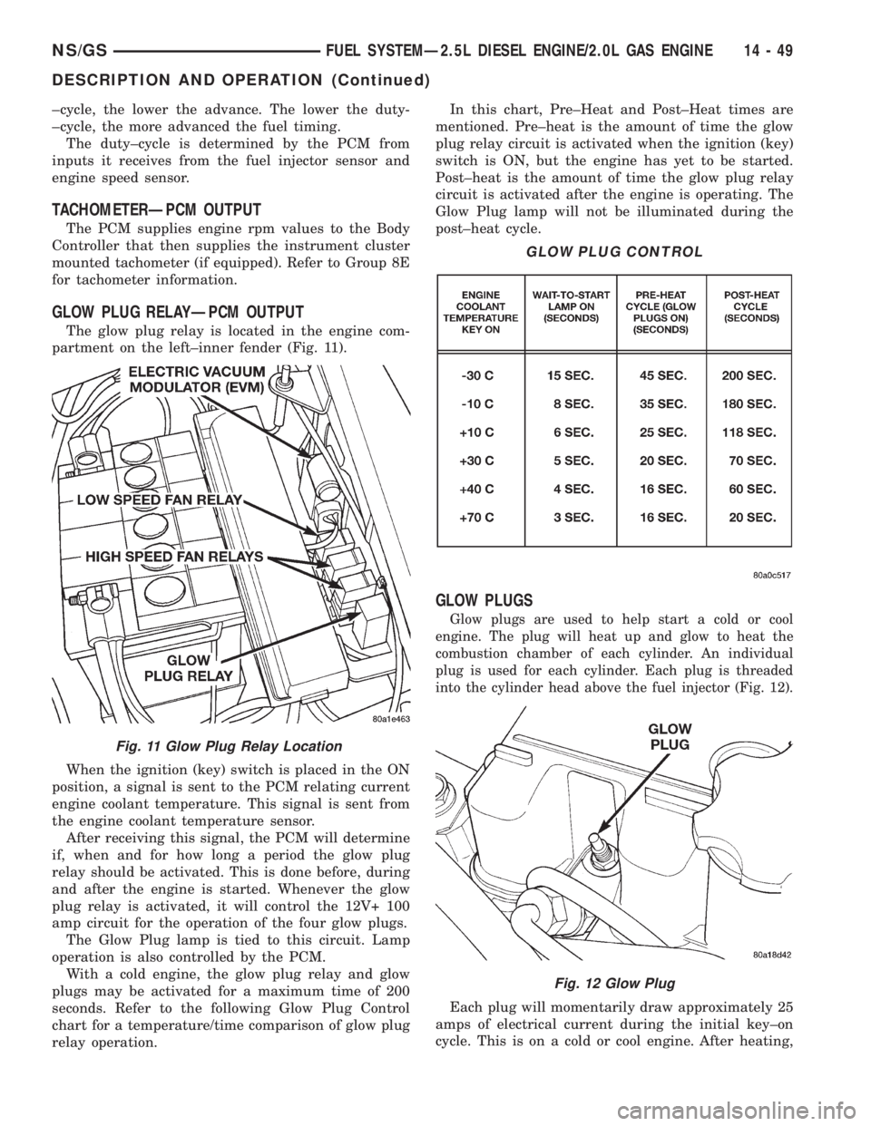
GLOW PLUG RELAYÐPCM OUTPUT
The glow plug relay is located in the engine com-
partment on the left±inner fender (Fig. 11).
When the ignition (key) switch is placed in the ON
position, a signal is sent to the PCM relating current
engine coolant temperature. This signal is sent from
the engine coolant temperature sensor.
After receiving this signal, the PCM will determine
if, when and for how long a period the glow plug
relay should be activated. This is done before, during
and after the engine is started. Whenever the glow
plug relay is activated, it will control the 12V+ 100
amp circuit for the operation of the four glow plugs.
The Glow Plug lamp is tied to this circuit. Lamp
operation is also controlled by the PCM.
With a cold engine, the glow plug relay and glow
plugs may be activated for a maximum time of 200
seconds. Refer to the following Glow Plug Control
chart for a temperature/time comparison of glow plug
relay operation.In this chart, Pre±Heat and Post±Heat times are
mentioned. Pre±heat is the amount of time the glow
plug relay circuit is activated when the ignition (key)
switch is ON, but the engine has yet to be started.
Post±heat is the amount of time the glow plug relay
circuit is activated after the engine is operating. The
Glow Plug lamp will not be illuminated during the
post±heat cycle.
GLOW PLUGS
Glow plugs are used to help start a cold or cool
engine. The plug will heat up and glow to heat the
combustion chamber of each cylinder. An individual
plug is used for each cylinder. Each plug is threaded
into the cylinder head above the fuel injector (Fig. 12).
Each plug will momentarily draw approximately 25
amps of electrical current during the initial key±on
cycle. This is on a cold or cool engine. After heating,
Fig. 11 Glow Plug Relay Location
GLOW PLUG CONTROL
Fig. 12 Glow Plug
NS/GSFUEL SYSTEMÐ2.5L DIESEL ENGINE/2.0L GAS ENGINE 14 - 49
DESCRIPTION AND OPERATION (Continued)
Page 1418 of 1938
the current draw will drop to approximately 9±12
amps per plug.
Total momentary current draw for all four plugs is
approximately 100 amps on a cold engine dropping to
a total of approximately 40 amps after the plugs are
heated.
Electrical operation of the glow plugs are con-
trolled by the glow plug relay. Refer to the previous
Glow Plug RelayÐPCM Output for additional infor-
mation.
EXHAUST GAS RECIRCULATION (EGR)
SOLENOIDÐPCM OUTPUT
This circuit controls operation of the Exhaust Gas
Recirculation (EGR) solenoid. The EGR solenoid (Fig.
11) controls operation of the EGR valve.
Refer to Group 25, Emission Control System for
information. See EGR solenoid.
DIAGNOSIS AND TESTING
DIESEL DIAGONSTICS
The PCM controller does engine off diagonstics
tests, which may be heard for about 60 seconds after
turning the key off.
DIESEL PCM RELAY TEST
To perform a test of the relay and its related cir-
cuitry, refer to the DRB scan tool. To test the relay
only, refer to RelaysÐOperation/Testing in this sec-
tion of the group.
Diagnostic Trouble Codes:Refer to On-Board
Diagnostics in Group 25, Emission Control System
for a list of Diagnostic Trouble Codes (DTC's) for cer-
tain fuel system components.
ENGINE SPEED SENSOR TEST
To perform a test of the engine speed sensor and
its related circuitry, refer to the DRB scan tool.
Diagnostic Trouble Codes:Refer to On-Board
Diagnostics in Group 25, Emission Control System
for a list of Diagnostic Trouble Codes (DTC's) for cer-
tain fuel system components.
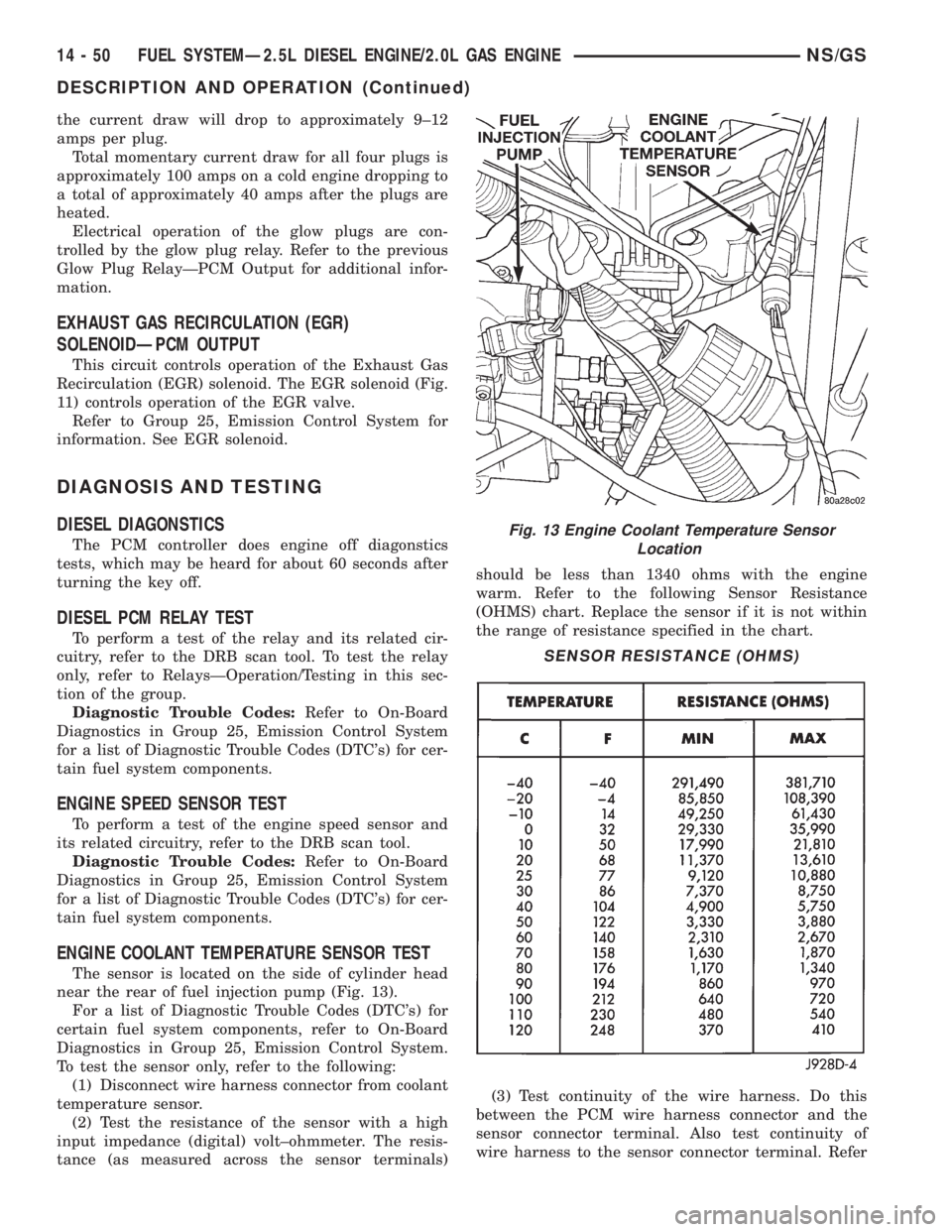
ENGINE COOLANT TEMPERATURE SENSOR TEST
The sensor is located on the side of cylinder head
near the rear of fuel injection pump (Fig. 13).
For a list of Diagnostic Trouble Codes (DTC's) for
certain fuel system components, refer to On-Board
Diagnostics in Group 25, Emission Control System.
To test the sensor only, refer to the following:
(1) Disconnect wire harness connector from coolant
temperature sensor.
(2) Test the resistance of the sensor with a high
input impedance (digital) volt±ohmmeter. The resis-
tance (as measured across the sensor terminals)should be less than 1340 ohms with the engine
warm. Refer to the following Sensor Resistance
(OHMS) chart. Replace the sensor if it is not within
the range of resistance specified in the chart.
(3) Test continuity of the wire harness. Do this
between the PCM wire harness connector and the
sensor connector terminal. Also test continuity of
wire harness to the sensor connector terminal. Refer
Fig. 13 Engine Coolant Temperature Sensor
Location
SENSOR RESISTANCE (OHMS)
14 - 50 FUEL SYSTEMÐ2.5L DIESEL ENGINE/2.0L GAS ENGINENS/GS
DESCRIPTION AND OPERATION (Continued)
Page 1419 of 1938
to Group 8W for wiring connector and circuitry infor-
mation. Repair the wire harness if an open circuit is
indicated.
(4) After tests are completed, connect electrical
connector to sensor.
GLOW PLUG TEST
Hard starting or a rough idle after starting may be
caused by one or more defective glow plugs. Before
testing the glow plugs, a test of the glow plug relay
should be performed. This will ensure that 12V+ is
available at the plugs when starting the engine.
Refer to the Glow Plug Relay Test for information.
For accurate test results, the glow plugs should be
removed from the engine. The plugs must be checked
when cold.Do not check the plugs if the engine
has recently been operated. If plugs are
checked when warm, incorrect amp gauge
readings will result.
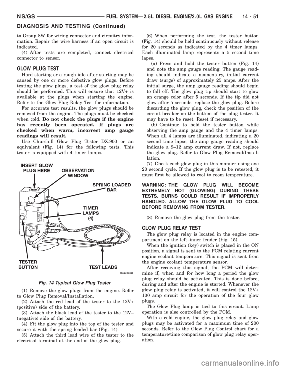
Use Churchill Glow Plug Tester DX.900 or an
equivalent (Fig. 14) for the following tests. This
tester is equipped with 4 timer lamps.
(1) Remove the glow plugs from the engine. Refer
to Glow Plug Removal/Installation.
(2) Attach the red lead of the tester to the 12V+
(positive) side of the battery.
(3) Attach the black lead of the tester to the 12V±
(negative) side of the battery.
(4) Fit the glow plug into the top of the tester and
secure it with the spring loaded bar (Fig. 14).
(5) Attach the third lead wire of the tester to the
electrical terminal at the end of the glow plug.(6) When performing the test, the tester button
(Fig. 14) should be held continuously without release
for 20 seconds as indicated by the 4 timer lamps.
Each illuminated lamp represents a 5 second time
lapse.
(a) Press and hold the tester button (Fig. 14)
and note the amp gauge reading. The gauge read-
ing should indicate a momentary, initial current
draw (surge) of approximately 25 amps. After the
initial surge, the amp gauge reading should begin
to fall off. The glow plug tip should start to glow
an orange color after 5 seconds. If the tip did not
glow after 5 seconds, replace the glow plug. Before
discarding the glow plug, check the position of the
circuit breaker on the bottom of the plug tester. It
may have to be reset. Reset if necessary.
(b) Continue to hold the tester button while
observing the amp gauge and the 4 timer lamps.
When all 4 lamps are illuminated, indicating a 20
second time lapse, the amp gauge reading should
indicate a 9±12 amp current draw. If not, replace
the glow plug. Refer to Glow Plug Removal/Instal-
lation.
(7) Check each glow plug in this manner using one
20 second cycle. If the glow plug is to be retested, it
must first be allowed to cool to room temperature.
WARNING: THE GLOW PLUG WILL BECOME
EXTREMELY HOT (GLOWING) DURING THESE
TESTS. BURNS COULD RESULT IF IMPROPERLY
HANDLED. ALLOW THE GLOW PLUG TO COOL
BEFORE REMOVING FROM TESTER.
(8) Remove the glow plug from the tester.
GLOW PLUG RELAY TEST
The glow plug relay is located in the engine com-
partment on the left±inner fender (Fig. 15).
When the ignition (key) switch is placed in the ON
position, a signal is sent to the PCM relating current
engine coolant temperature. This signal is sent from
the engine coolant temperature sensor.
After receiving this signal, the PCM will deter-
mine if, when and for how long a period the glow
plug relay should be activated. This is done before,
during and after the engine is started. Whenever the
glow plug relay is activated, it will control the 12V+
100 amp circuit for the operation of the four glow
plugs.
The Glow Plug lamp is tied to this circuit. Lamp
operation is also controlled by the PCM.
With a cold engine, the glow plug relay and glow
plugs may be activated for a maximum time of 200
seconds. Refer to the Glow Plug Control chart for a
temperature/time comparison of glow plug relay oper-
ation.
Fig. 14 Typical Glow Plug Tester
NS/GSFUEL SYSTEMÐ2.5L DIESEL ENGINE/2.0L GAS ENGINE 14 - 51
DIAGNOSIS AND TESTING (Continued)
Page 1422 of 1938
(2) Remove the sensor mounting bolts.
(3) Remove the sensor.
INSTALLATION
(1) Install the sensor flush against the opening in
the transmission housing.
(2) Install and tighten the sensor mounting bolt to
19 N´m (14 ft. lbs.) torque.
(3) Connect the electrical connector to the sensor.
ENGINE COOLANT TEMPERATURE SENSOR
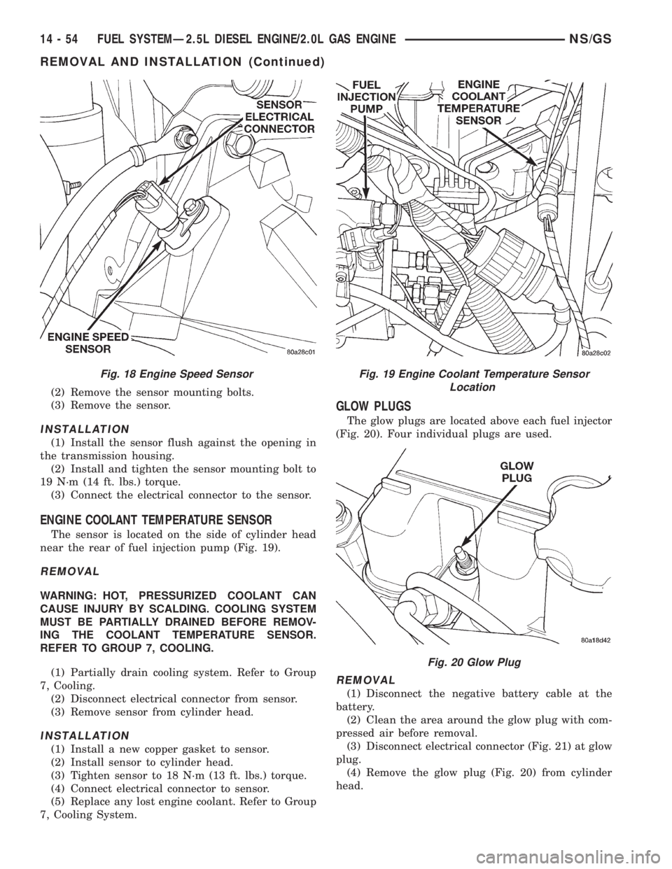
The sensor is located on the side of cylinder head
near the rear of fuel injection pump (Fig. 19).
REMOVAL
WARNING: HOT, PRESSURIZED COOLANT CAN
CAUSE INJURY BY SCALDING. COOLING SYSTEM
MUST BE PARTIALLY DRAINED BEFORE REMOV-
ING THE COOLANT TEMPERATURE SENSOR.
REFER TO GROUP 7, COOLING.
(1) Partially drain cooling system. Refer to Group
7, Cooling.
(2) Disconnect electrical connector from sensor.
(3) Remove sensor from cylinder head.
INSTALLATION
(1) Install a new copper gasket to sensor.
(2) Install sensor to cylinder head.
(3) Tighten sensor to 18 N´m (13 ft. lbs.) torque.
(4) Connect electrical connector to sensor.
(5) Replace any lost engine coolant. Refer to Group
7, Cooling System.
GLOW PLUGS
The glow plugs are located above each fuel injector
(Fig. 20). Four individual plugs are used.
REMOVAL
(1) Disconnect the negative battery cable at the
battery.
(2) Clean the area around the glow plug with com-
pressed air before removal.
(3) Disconnect electrical connector (Fig. 21) at glow
plug.
(4) Remove the glow plug (Fig. 20) from cylinder
head.
Fig. 18 Engine Speed SensorFig. 19 Engine Coolant Temperature Sensor
Location
Fig. 20 Glow Plug
14 - 54 FUEL SYSTEMÐ2.5L DIESEL ENGINE/2.0L GAS ENGINENS/GS
REMOVAL AND INSTALLATION (Continued)