1996 CHRYSLER VOYAGER coolant temperature
[x] Cancel search: coolant temperaturePage 1390 of 1938
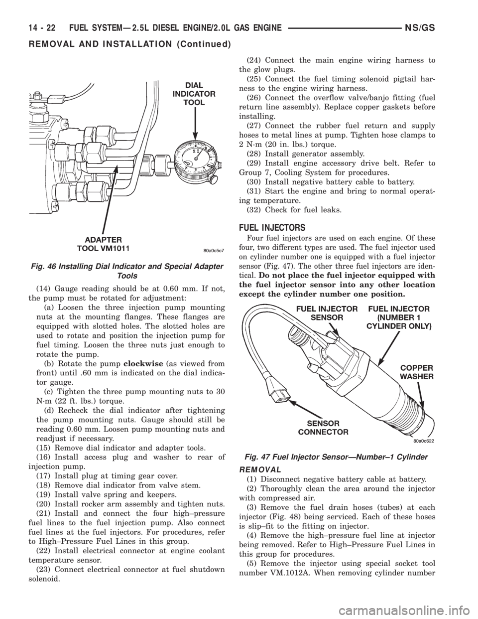
(14) Gauge reading should be at 0.60 mm. If not,
the pump must be rotated for adjustment:
(a) Loosen the three injection pump mounting
nuts at the mounting flanges. These flanges are
equipped with slotted holes. The slotted holes are
used to rotate and position the injection pump for
fuel timing. Loosen the three nuts just enough to
rotate the pump.
(b) Rotate the pumpclockwise(as viewed from
front) until .60 mm is indicated on the dial indica-
tor gauge.
(c) Tighten the three pump mounting nuts to 30
N´m (22 ft. lbs.) torque.
(d) Recheck the dial indicator after tightening
the pump mounting nuts. Gauge should still be
reading 0.60 mm. Loosen pump mounting nuts and
readjust if necessary.
(15) Remove dial indicator and adapter tools.
(16) Install access plug and washer to rear of
injection pump.
(17) Install plug at timing gear cover.
(18) Remove dial indicator from valve stem.
(19) Install valve spring and keepers.
(20) Install rocker arm assembly and tighten nuts.
(21) Install and connect the four high±pressure
fuel lines to the fuel injection pump. Also connect
fuel lines at the fuel injectors. For procedures, refer
to High±Pressure Fuel Lines in this group.
(22) Install electrical connector at engine coolant
temperature sensor.
(23) Connect electrical connector at fuel shutdown
solenoid.(24) Connect the main engine wiring harness to
the glow plugs.
(25) Connect the fuel timing solenoid pigtail har-
ness to the engine wiring harness.
(26) Connect the overflow valve/banjo fitting (fuel
return line assembly). Replace copper gaskets before
installing.
(27) Connect the rubber fuel return and supply
hoses to metal lines at pump. Tighten hose clamps to
2 N´m (20 in. lbs.) torque.
(28) Install generator assembly.
(29) Install engine accessory drive belt. Refer to
Group 7, Cooling System for procedures.
(30) Install negative battery cable to battery.
(31) Start the engine and bring to normal operat-
ing temperature.
(32) Check for fuel leaks.
FUEL INJECTORS
Four fuel injectors are used on each engine. Of these
four, two different types are used. The fuel injector used
on cylinder number one is equipped with a fuel injector
sensor (Fig. 47). The other three fuel injectors are iden-
tical.
Do not place the fuel injector equipped with
the fuel injector sensor into any other location
except the cylinder number one position.
REMOVAL
(1) Disconnect negative battery cable at battery.
(2) Thoroughly clean the area around the injector
with compressed air.
(3) Remove the fuel drain hoses (tubes) at each
injector (Fig. 48) being serviced. Each of these hoses
is slip±fit to the fitting on injector.
(4) Remove the high±pressure fuel line at injector
being removed. Refer to High±Pressure Fuel Lines in
this group for procedures.
(5) Remove the injector using special socket tool
number VM.1012A. When removing cylinder number
Fig. 46 Installing Dial Indicator and Special Adapter
Tools
Fig. 47 Fuel Injector SensorÐNumber±1 Cylinder
14 - 22 FUEL SYSTEMÐ2.5L DIESEL ENGINE/2.0L GAS ENGINENS/GS
REMOVAL AND INSTALLATION (Continued)
Page 1400 of 1938
FUEL INJECTION SYSTEMÐ2.0L ENGINE
INDEX
page page
GENERAL INFORMATION
INTRODUCTIONÐ2.0L ENGINE............ 32
MODES OF OPERATIONÐ2.0L ENGINE..... 32
DESCRIPTION AND OPERATION
AIR CONDITIONING (A/C) RELAYÐPCM
OUTPUTÐ2.0L ENGINE................ 35
AIR CONDITIONING PRESSURE
TRANSDUCERÐPCM INPUTÐ
2.0L ENGINE......................... 33
AIR CONDITIONING SWITCH SENSEÐ
PCM INPUTÐ2.0L ENGINE.............. 33
AUTOMATIC SHUTDOWN (ASD) SENSEÐ
PCM INPUTÐ2.0L ENGINE.............. 33
AUTOMATIC SHUTDOWN RELAYÐ
PCM OUTPUTÐ2.0L ENGINE............ 35
BATTERY VOLTAGEÐPCM INPUTÐ
2.0L ENGINE......................... 33
CAMSHAFT POSITION SENSORÐ
PCM INPUTÐ2.0L ENGINE.............. 33
CRANKSHAFT POSITION SENSORÐ
PCM INPUTÐ2.0L ENGINE.............. 33
DATA LINK CONNECTORÐPCM OUTPUTÐ
2.0L ENGINE......................... 35
ELECTRONIC EGR TRANSDUCERÐ
PCM OUTPUTÐ2.0L ENGINE............ 35
ENGINE COOLANT TEMPERATURE SENSORÐ
PCM INPUTÐ2.0L ENGINE.............. 33
FUEL INJECTORSÐPCM OUTPUTÐ
2.0L ENGINE......................... 35
FUEL PUMP RELAYÐPCM OUTPUTÐ
2.0L ENGINE......................... 35
GENERATOR FIELDÐPCM OUTPUTÐ
2.0L ENGINE......................... 35
HEATED OXYGEN SENSORÐPCM INPUTÐ
2.0L ENGINE......................... 33
IDLE AIR CONTROL MOTORÐPCM OUTPUTÐ
2.0L ENGINE......................... 35
IGNITION COILÐPCM OUTPUTÐ
2.0L ENGINE......................... 36KNOCK SENSORÐPCM INPUTÐ
2.0L ENGINE......................... 34
MALFUNCTION INDICATOR (CHECK ENGINE)
LAMPÐPCM OUTPUTÐ2.0L ENGINE...... 36
MANIFOLD ABSOLUTE PRESSURE
(MAP SENSOR)ÐPCM INPUTÐ
2.0L ENGINE......................... 34
POWERTRAIN CONTROL MODULEÐ
2.0L ENGINE......................... 33
RADIATOR FAN CONTROL MODULEÐ
PCM OUTPUTÐ2.0L ENGINE............ 36
SPEED CONTROL SOLENOIDSÐ
PCM OUTPUTÐ2.0L ENGINE............ 36
SPEED CONTROLÐPCM INPUTÐ
2.0L ENGINE......................... 34
STARTER RELAYÐPCM OUTPUTÐ
2.0L ENGINE......................... 35
SYSTEM DIAGNOSISÐ2.0L ENGINE........ 33
TACHOMETERÐPCM OUTPUTÐ
2.0L ENGINE......................... 36
THROTTLE BODYÐ2.0L ENGINE.......... 36
THROTTLE POSITION SENSOR/ IDLE AIR
CONTROL MOTORÐPCM INPUTÐ
2.0L ENGINE......................... 35
DIAGNOSIS AND TESTING
ASD AND FUEL PUMP RELAYSÐ
2.0L ENGINE......................... 39
CAMSHAFT AND CRANKSHAFT
POSITION SENSOR................... 40
ENGINE COOLANT TEMPERATURE
SENSOR............................ 40
KNOCK SENSORÐ2.0L ENGINE........... 40
MANIFOLD ABSOLUTE PRESSURE
(MAP) SENSORÐ2.0L ENGINE........... 39
THROTTLE BODY MINIMUM AIR FLOW..... 41
THROTTLE POSITION SENSOR........... 40
VISUAL INSPECTIONÐSOHC............. 36
SPECIFICATIONS
TORQUE............................. 42
GENERAL INFORMATION
INTRODUCTIONÐ2.0L ENGINE
Refer to the Introduction for 2.4/3.0/3.3/3.8L
engines under General Information in the Fuel Injec-
tion System section of group 14 for more information.
MODES OF OPERATIONÐ2.0L ENGINE
Refer to the Modes of Operation for 2.4/3.0/3.3/3.8L
engines under General Information in the Fuel Injec-
tion System section of group 14 for more information.
14 - 32 FUEL SYSTEMÐ2.5L DIESEL ENGINE/2.0L GAS ENGINENS/GS
Page 1401 of 1938
DESCRIPTION AND OPERATION
SYSTEM DIAGNOSISÐ2.0L ENGINE
Refer to System diagnosis for 2.4/3.0/3.3/3.8L
engines under Description and Operation in the Fuel
Injection System section of group 14 for more infor-
mation.
POWERTRAIN CONTROL MODULEÐ2.0L ENGINE
Refer to the Powertrain Control Module for 2.4/3.0/
3.3/3.8L engines under Description and Operation in
the Fuel Injection System section of group 14 for
more information.
AIR CONDITIONING PRESSURE TRANSDUCERÐ
PCM INPUTÐ2.0L ENGINE
Refer to the Air Conditioning Pressure Transducer
for 2.4/3.0/3.3/3.8L engines under Description and
Operation in the Fuel Injection System section of
group 14 for more information.
AIR CONDITIONING SWITCH SENSEÐPCM
INPUTÐ2.0L ENGINE
Refer to the Air Conditioning Switch Sense for 2.4/
3.0/3.3/3.8L engines under Description and Operation
in the Fuel Injection System section of group 14 for
more information.
AUTOMATIC SHUTDOWN (ASD) SENSEÐPCM
INPUTÐ2.0L ENGINE
Refer to the Automatic Shutdown (ASD) Sense for
2.4/3.0/3.3/3.8L engines under Description and Oper-
ation in the Fuel Injection System section of group 14
for more information.
BATTERY VOLTAGEÐPCM INPUTÐ2.0L ENGINE
Refer to the Battery Voltage for 2.4/3.0/3.3/3.8L
engines under Description and Operation in the Fuel
Injection System section of group 14 for more infor-
mation.
CAMSHAFT POSITION SENSORÐPCM INPUTÐ
2.0L ENGINE
Refer to the Camshaft Position Sensor for 2.4L
engine under Description and Operation in the Fuel
Injection System section of group 14 for more infor-
mation.
CRANKSHAFT POSITION SENSORÐPCM
INPUTÐ2.0L ENGINE
Refer to the Crankshaft Position Sensor for 2.4L
engine under Description and Operation in the Fuel
Injection System section of group 14 for more infor-
mation.
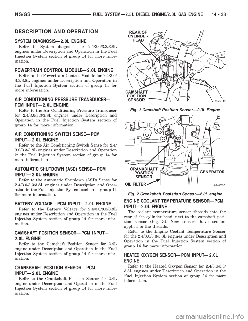
ENGINE COOLANT TEMPERATURE SENSORÐPCM
INPUTÐ2.0L ENGINE
The coolant temperature sensor threads into the
rear of the cylinder head, next to the camshaft posi-
tion sensor (Fig. 3). New sensors have sealant
applied to the threads.
Refer to the Engine Coolant Temperature Sensor
for the 2.4/3.0/3.3/3.8L engines under Description and
Operation in the Fuel Injection System section of
group 14 for more information.
HEATED OXYGEN SENSORÐPCM INPUTÐ2.0L
ENGINE
Refer to the Heated Oxygen Sensor for 2.4/3.0/3.3/
3.8L engines under Description and Operation in the
Fuel Injection System section of group 14 for more
information.
Fig. 1 Camshaft Position SensorÐ2.0L Engine
Fig. 2 Crankshaft Posistion SensorÐ2.0L engine
NS/GSFUEL SYSTEMÐ2.5L DIESEL ENGINE/2.0L GAS ENGINE 14 - 33
Page 1402 of 1938
KNOCK SENSORÐPCM INPUTÐ2.0L ENGINE
Refer to the Knock Sensor for 2.4/3.0/3.3/3.8L
engines under Description and Operation in the Fuel
Injection System section of group 14 for more infor-
mation.
MANIFOLD ABSOLUTE PRESSURE (MAP
SENSOR)ÐPCM INPUTÐ2.0L ENGINE
Refer to the Manifold Absolute Pressure and
Intake Air Temperature sensors for 2.4/3.0/3.3/3.8L
engines under Description and Operation in the Fuel
Injection System section of group 14 for more infor-
mation.
SPEED CONTROLÐPCM INPUTÐ2.0L ENGINE
Refer to the Speed Control for 2.4/3.0/3.3/3.8L
engines under Description and Operation in the Fuel
Injection System section of group 14 for more infor-
mation.
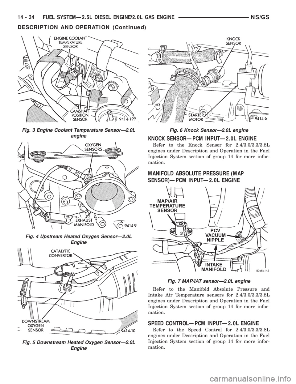
Fig. 3 Engine Coolant Temperature SensorÐ2.0L
engine
Fig. 4 Upstream Heated Oxygen SensorÐ2.0L
Engine
Fig. 5 Downstream Heated Oxygen SensorÐ2.0L
Engine
Fig. 6 Knock SensorÐ2.0L engine
Fig. 7 MAP/IAT sensorÐ2.0L engine
14 - 34 FUEL SYSTEMÐ2.5L DIESEL ENGINE/2.0L GAS ENGINENS/GS
DESCRIPTION AND OPERATION (Continued)
Page 1405 of 1938
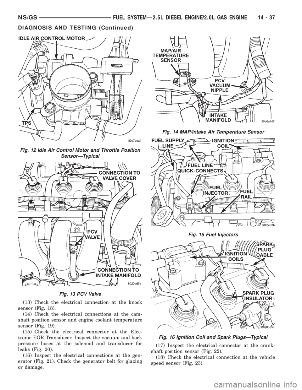
(13) Check the electrical connection at the knock
sensor (Fig. 18).
(14) Check the electrical connections at the cam-
shaft position sensor and engine coolant temperature
sensor (Fig. 19).
(15) Check the electrical connector at the Elec-
tronic EGR Transducer. Inspect the vacuum and back
pressure hoses at the solenoid and transducer for
leaks (Fig. 20).
(16) Inspect the electrical connections at the gen-
erator (Fig. 21). Check the generator belt for glazing
or damage.(17) Inspect the electrical connector at the crank-
shaft position sensor (Fig. 22).
(18) Check the electrical connection at the vehicle
speed sensor (Fig. 23).
Fig. 12 Idle Air Control Motor and Throttle Position
SensorÐTypical
Fig. 13 PCV Valve
Fig. 14 MAP/Intake Air Temperature Sensor
Fig. 15 Fuel Injectors
Fig. 16 Ignition Coil and Spark PlugsÐTypical
NS/GSFUEL SYSTEMÐ2.5L DIESEL ENGINE/2.0L GAS ENGINE 14 - 37
DIAGNOSIS AND TESTING (Continued)
Page 1406 of 1938
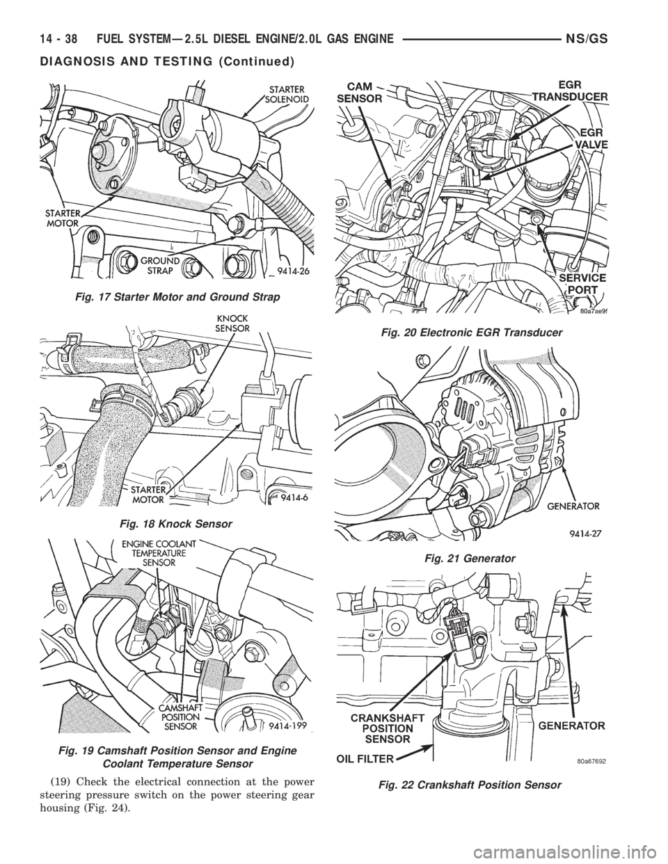
(19) Check the electrical connection at the power
steering pressure switch on the power steering gear
housing (Fig. 24).
Fig. 17 Starter Motor and Ground Strap
Fig. 18 Knock Sensor
Fig. 19 Camshaft Position Sensor and Engine
Coolant Temperature Sensor
Fig. 20 Electronic EGR Transducer
Fig. 21 Generator
Fig. 22 Crankshaft Position Sensor
14 - 38 FUEL SYSTEMÐ2.5L DIESEL ENGINE/2.0L GAS ENGINENS/GS
DIAGNOSIS AND TESTING (Continued)
Page 1408 of 1938
CAUTION: When testing the MAP sensor, be sure
that the harness wires are not damaged by the test
meter probes.
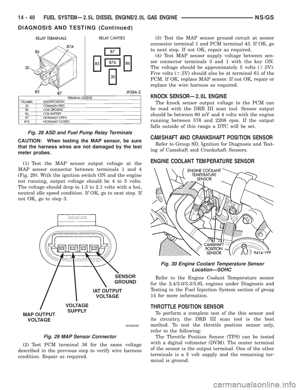
(1) Test the MAP sensor output voltage at the
MAP sensor connector between terminals 1 and 4
(Fig. 29). With the ignition switch ON and the engine
not running, output voltage should be 4 to 5 volts.
The voltage should drop to 1.5 to 2.1 volts with a hot,
neutral idle speed condition. If OK, go to next step. If
not OK, go to step 3.
(2) Test PCM terminal 36 for the same voltage
described in the previous step to verify wire harness
condition. Repair as required.(3) Test the MAP sensor ground circuit at sensor
connector terminal 1 and PCM terminal 43. If OK, go
to next step. If not OK, repair as required.
(4) Test MAP sensor supply voltage between sen-
sor connector terminals 3 and 1 with the key ON.
The voltage should be approximately 5 volts (6.5V).
Five volts (6.5V) should also be at terminal 61 of the
PCM. If OK, replace MAP sensor. If not OK, repair or
replace the wire harness as required.
KNOCK SENSORÐ2.0L ENGINE
The knock sensor output voltage to the PCM can
be read with the DRB III scan tool. Sensor output
should be between 80 mV and 4 volts with the engine
running between 576 and 2208 rpm. If the output
falls outside of this range a DTC will be set.
CAMSHAFT AND CRANKSHAFT POSITION SENSOR
Refer to Group 8D, Ignition for Diagnosis and Test-
ing of Camshaft and Crankshaft Sensors.
ENGINE COOLANT TEMPERATURE SENSOR
Refer to the Engine Coolant Temperature sensor
for the 2.4/3.0/3.3/3.8L engines under Diagnosis and
Testing in the Fuel Injection System section of group
14 for more information.
THROTTLE POSITION SENSOR
To perform a complete test of the this sensor and
its circuitry, the DRB III scan tool is the best
method. To test the throttle position sensor only,
refer to the following:
The Throttle Position Sensor (TPS) can be tested
with a digital voltmeter (DVM). The center terminal
of the sensor is the output terminal. One of the other
terminals is a 5 volt supply and the remaining ter-
minal is ground.
Fig. 28 ASD and Fuel Pump Relay Terminals
Fig. 29 MAP Sensor Connector
Fig. 30 Engine Coolant Temperature Sensor
LocationÐSOHC
14 - 40 FUEL SYSTEMÐ2.5L DIESEL ENGINE/2.0L GAS ENGINENS/GS
DIAGNOSIS AND TESTING (Continued)
Page 1410 of 1938
(a) Remove the throttle body from engine.
(b) While holding the throttle open, spray the
entire throttle body bore and the manifold side of
the throttle plate with Mopar Parts Cleaner.Only
use Mopar Parts Cleaner to clean the throttle
body.
(c) Using a soft scuff pad, clean the top and bot-
tom of throttle body bore and the edges and mani-
fold side of the throttle blade.The edges of the
throttle blade and portions of the throttle
bore that are closest to the throttle blade
when closed, must be free of deposits.
(d) Use compressed air to dry the throttle body.
(e) Inspect throttle body for foreign material.
(f) Install throttle body on manifold.
(g) Repeat steps 1 through 14. If the minimum
air flow is still not within specifications, the prob-
lem is not caused by the throttle body.
(12) Shut off engine.
(13) Remove Air Metering Orifice 6457. Install
purge hose.
(14) Remove cap from PCV valve. Connect hose to
PCV valve.
(15) Remove DRB scan tool.SPECIFICATIONS
TORQUE
DESCRIPTION TORQUE
Air Cleaner Wingnut.........1.5N´m(15in.lbs.)
Air Cleaner Mount. Stud-To-Thrott. Body . . 10 N´m
(90 in. lbs.)
Crankshaft Position Sensor Mounting Bolts . . 8 N´m
(70 in. lbs.)
Engine Coolant Temperature Sensor......18N´m
(165 in. lbs.)
IAC Motor-To-Throttle Body Bolts.........7N´m
(60 in. lbs.)
MAP/IAT Sensor.............2N´m(20in.lbs.)
MAP/IAT Sensor.............3N´m(30in.lbs.)
Oxygen Sensor..............28N´m(20ft.lbs.)
Powertrain Control Module
(PCM) Mounting Screws.....4N´m(35in.lbs.)
Throttle Cable Cover........4.5N´m(40in.lbs.).
Throttle Body Mounting Bolts...........23N´m
(200 in. lbs.)
Throttle Position Sensor Mounting Screws . . . 2 N´m
(20 in. lbs.)
Vehicle Speed Sensor Mounting Bolt......2.2N´m
(20 in. lbs.)
14 - 42 FUEL SYSTEMÐ2.5L DIESEL ENGINE/2.0L GAS ENGINENS/GS
DIAGNOSIS AND TESTING (Continued)