1996 CHRYSLER VOYAGER check engine
[x] Cancel search: check enginePage 1101 of 1938
(4) Wash all parts in a suitable solvent and
inspect carefully for damage or wear.
ASSEMBLY
(1) Assemble pump, using new parts as required.
Install the inner rotor with chamfer facing the
cast iron oil pump cover.
(2) Prime oil pump before installation by filling
rotor cavity with engine oil.
(3) Install cover and tighten screws to 12 N´m
(105 in. lbs.).
CAUTION: Oil pump pressure relief valve must be
installed as shown in (Fig. 95) or serious damage
may occur.
(4) Install relief valve, spring, gasket and cap as
shown in (Fig. 95). Tighten cap to 41 N´m (30 ft. lbs.)
CLEANING AND INSPECTION
CYLINDER HEAD
CLEANING
Remove all gasket material from cylinder head and
block. Be careful not to gouge or scratch the alumi-
num head sealing surface.
INSPECTION
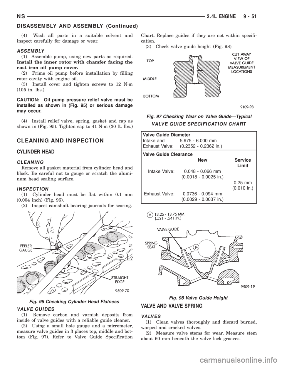
(1) Cylinder head must be flat within 0.1 mm
(0.004 inch) (Fig. 96).
(2) Inspect camshaft bearing journals for scoring.
VALVE GUIDES
(1) Remove carbon and varnish deposits from
inside of valve guides with a reliable guide cleaner.
(2) Using a small hole gauge and a micrometer,
measure valve guides in 3 places top, middle and bot-
tom (Fig. 97). Refer to Valve Guide SpecificationChart. Replace guides if they are not within specifi-
cation.
(3) Check valve guide height (Fig. 98).
VALVE AND VALVE SPRING
VALVES
(1) Clean valves thoroughly and discard burned,
warped and cracked valves.
(2) Measure valve stems for wear. Measure stem
about 60 mm beneath the valve lock grooves.
Fig. 96 Checking Cylinder Head Flatness
Fig. 97 Checking Wear on Valve GuideÐTypical
VALVE GUIDE SPECIFICATION CHART
Valve Guide Diameter
Intake and
Exhaust Valve:5.975 - 6.000 mm
(0.2352 - 0.2362 in.)
Valve Guide Clearance
New Service
Limit
Intake Valve: 0.048 - 0.066 mm
(0.0018 - 0.0025 in.)
0.25 mm
(0.010 in.)
Exhaust Valve: 0.0736 - 0.094 mm
(0.0029 - 0.0037 in.)
Fig. 98 Valve Guide Height
NS2.4L ENGINE 9 - 51
DISASSEMBLY AND ASSEMBLY (Continued)
Page 1102 of 1938
(3) If valve stems are worn more than 0.05 mm
(.002 in.), replace valve.
VALVE SPRINGS
(1) Whenever valves have been removed for
inspection, reconditioning or replacement, valve
springs should be tested for correct tension. Discard
the springs that do not meet specifications. The fol-
lowing specifications apply to both intake and
exhaust valves springs:
²Valve Closed Nominal TensionÐ 76 lbs. @ 38.0
mm (1.50 in.)
²Valve Open Nominal TensionÐ 136 lbs. @ 29.75
mm (1.17 in.)
(2) Inspect each valve spring for squareness with
a steel square and surface plate, test springs from
both ends. If the spring is more than 1.5 mm (1/16
inch) out of square, install a new spring.
CRANKSHAFT
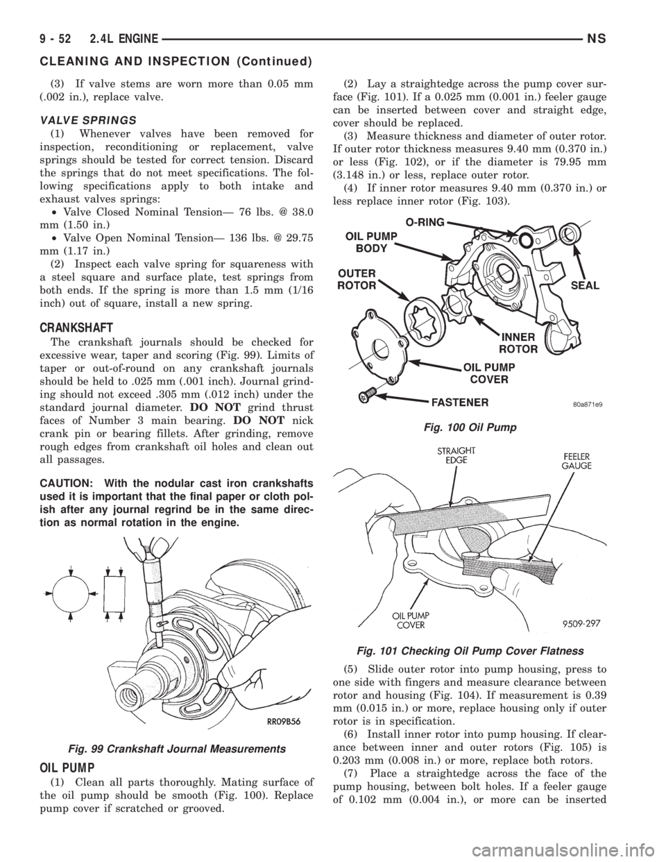
The crankshaft journals should be checked for
excessive wear, taper and scoring (Fig. 99). Limits of
taper or out-of-round on any crankshaft journals
should be held to .025 mm (.001 inch). Journal grind-
ing should not exceed .305 mm (.012 inch) under the
standard journal diameter.DO NOTgrind thrust
faces of Number 3 main bearing.DO NOTnick
crank pin or bearing fillets. After grinding, remove
rough edges from crankshaft oil holes and clean out
all passages.
CAUTION: With the nodular cast iron crankshafts
used it is important that the final paper or cloth pol-
ish after any journal regrind be in the same direc-
tion as normal rotation in the engine.
OIL PUMP
(1) Clean all parts thoroughly. Mating surface of
the oil pump should be smooth (Fig. 100). Replace
pump cover if scratched or grooved.(2) Lay a straightedge across the pump cover sur-
face (Fig. 101). If a 0.025 mm (0.001 in.) feeler gauge
can be inserted between cover and straight edge,
cover should be replaced.
(3) Measure thickness and diameter of outer rotor.
If outer rotor thickness measures 9.40 mm (0.370 in.)
or less (Fig. 102), or if the diameter is 79.95 mm
(3.148 in.) or less, replace outer rotor.
(4) If inner rotor measures 9.40 mm (0.370 in.) or
less replace inner rotor (Fig. 103).
(5) Slide outer rotor into pump housing, press to
one side with fingers and measure clearance between
rotor and housing (Fig. 104). If measurement is 0.39
mm (0.015 in.) or more, replace housing only if outer
rotor is in specification.
(6) Install inner rotor into pump housing. If clear-
ance between inner and outer rotors (Fig. 105) is
0.203 mm (0.008 in.) or more, replace both rotors.
(7) Place a straightedge across the face of the
pump housing, between bolt holes. If a feeler gauge
of 0.102 mm (0.004 in.), or more can be inserted
Fig. 99 Crankshaft Journal Measurements
Fig. 100 Oil Pump
Fig. 101 Checking Oil Pump Cover Flatness
9 - 52 2.4L ENGINENS
CLEANING AND INSPECTION (Continued)
Page 1104 of 1938
CYLINDER BLOCK
(1) Clean cylinder block thoroughly and check all
core hole plugs for evidence of leaking.
(2) If new core plugs are installed, refer to Engine
Core Plugs outlined in this section.
(3) Examine block and cylinder bores for cracks or
fractures.
CYLINDER BORE INSPECTION
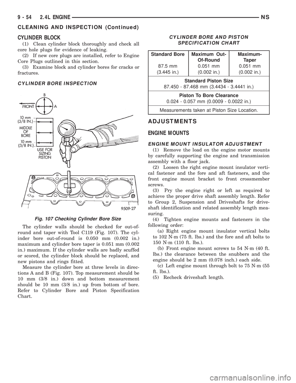
The cylinder walls should be checked for out-of-
round and taper with Tool C119 (Fig. 107). The cyl-
inder bore out-of-round is 0.050 mm (0.002 in.)
maximum and cylinder bore taper is 0.051 mm (0.002
in.) maximum. If the cylinder walls are badly scuffed
or scored, the cylinder block should be replaced, and
new pistons and rings fitted.
Measure the cylinder bore at three levels in direc-
tions A and B (Fig. 107). Top measurement should be
10 mm (3/8 in.) down and bottom measurement
should be 10 mm (3/8 in.) up from bottom of bore.
Refer to Cylinder Bore and Piston Specification
Chart.
ADJUSTMENTS
ENGINE MOUNTS
ENGINE MOUNT INSULATOR ADJUSTMENT
(1) Remove the load on the engine motor mounts
by carefully supporting the engine and transmission
assembly with a floor jack.
(2) Loosen the right engine mount insulator verti-
cal fastener and the fore and aft fasteners, and the
front engine mount bracket to front crossmember
screws.
(3) Pry the engine right or left as required to
achieve the proper drive shaft assembly length. Refer
to Group 2, Suspension and Driveshafts for drive-
shaft identification and related assembly length mea-
suring.
(4) Tighten engine mounts and fasteners in the
following order:
(a) Right engine mount insulator vertical bolts
to 102 N´m (75 ft. lbs.) and the fore and aft bolts to
150 N´m (110 ft. lbs.).
(b) Front engine mount screws to 54 N´m (40 ft.
lbs.) the clearance between the snubbers and the
engine should be 2 mm (0.078 inch.) each side.
(c) Left engine mount through bolt to 75 N´m (55
ft. lbs.).
(5) Recheck driveshaft length.
Fig. 107 Checking Cylinder Bore Size
CYLINDER BORE AND PISTON
SPECIFICATION CHART
Standard Bore Maximum Out-
Of-RoundMaximum-
Taper
87.5 mm 0.051 mm 0.051 mm
(3.445 in.) (0.002 in.) (0.002 in.)
Standard Piston Size
87.450 - 87.468 mm (3.4434 - 3.4441 in.)
Piston To Bore Clearance
0.024 - 0.057 mm (0.0009 - 0.0022 in.)
Measurements taken at Piston Size Location.
9 - 54 2.4L ENGINENS
CLEANING AND INSPECTION (Continued)
Page 1111 of 1938
3.0L ENGINE
INDEX
page page
DESCRIPTION AND OPERATION
ENGINE COMPONENTS.................. 61
ENGINE IDENTIFICATION NUMBER......... 61
ENGINE LUBRICATION................... 61
DIAGNOSIS AND TESTING
CHECKING ENGINE OIL PRESSURE......... 62
SERVICE PROCEDURES
AUTO LASH ADJUSTER................... 62
CHECKING CRANKSHAFT END PLAY........ 65
FITTING CONNECTING ROD BEARINGS...... 63
FITTING MAIN BEARING.................. 63
VALVE SERVICE RECONDITION............ 66
REMOVAL AND INSTALLATION
CAMSHAFT SEAL....................... 72
CAMSHAFT............................ 71
CRANKSHAFT.......................... 81
CYLINDER HEAD COVER................. 70
CYLINDER HEAD........................ 73
ENGINE ASSEMBLY...................... 69
ENGINE MOUNTS....................... 68
FRONT CRANKSHAFT OIL SEAL............ 83OIL FILTER AND ADAPTOR................ 84
OILPAN ............................... 77
OIL PUMP............................. 84
PISTON AND CONNECTING ROD........... 78
REAR CRANKSHAFT SEAL................ 83
ROCKER ARMS......................... 72
TIMING BELT........................... 75
DISASSEMBLY AND ASSEMBLY
ROCKER ARMS AND SHAFTS.............. 85
CLEANING AND INSPECTION
CYLINDER BORE........................ 87
CYLINDER HEAD........................ 86
OIL PUMP............................. 87
TIMING BELT........................... 86
ADJUSTMENTS
ENGINE MOUNTS....................... 88
SPECIFICATIONS
3.0L ENGINE........................... 89
TORQUE CHART 3.0L.................... 90
SPECIAL TOOLS
3.0L ENGINE........................... 91
DESCRIPTION AND OPERATION
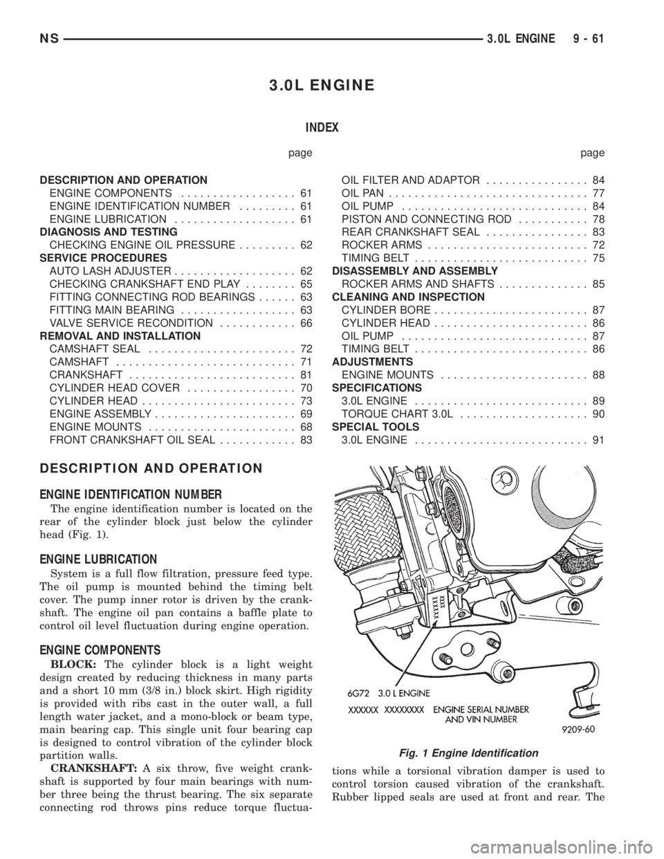
ENGINE IDENTIFICATION NUMBER
The engine identification number is located on the
rear of the cylinder block just below the cylinder
head (Fig. 1).
ENGINE LUBRICATION
System is a full flow filtration, pressure feed type.
The oil pump is mounted behind the timing belt
cover. The pump inner rotor is driven by the crank-
shaft. The engine oil pan contains a baffle plate to
control oil level fluctuation during engine operation.
ENGINE COMPONENTS
BLOCK:The cylinder block is a light weight
design created by reducing thickness in many parts
and a short 10 mm (3/8 in.) block skirt. High rigidity
is provided with ribs cast in the outer wall, a full
length water jacket, and a mono-block or beam type,
main bearing cap. This single unit four bearing cap
is designed to control vibration of the cylinder block
partition walls.
CRANKSHAFT:A six throw, five weight crank-
shaft is supported by four main bearings with num-
ber three being the thrust bearing. The six separate
connecting rod throws pins reduce torque fluctua-tions while a torsional vibration damper is used to
control torsion caused vibration of the crankshaft.
Rubber lipped seals are used at front and rear. The
Fig. 1 Engine Identification
NS3.0L ENGINE 9 - 61
Page 1112 of 1938
front seal is retained in the oil pump case and the
rear is retained in a block-mounted housing.
PISTONS:Are aluminum alloy with a steel strut,
short height, and thin wall so as to be autothermic
and light weight. The piston head with valve
recesses, in combination with the cylinder head,
forms a compact spherical head with clearance for
total valve lift with pistons at top dead center. The
piston skirt, top and second ring lands are finished to
a tapered roughness for oil retention and high resis-
tance to scuffing. Piston pins, pressed into place, join
the pistons to the connecting rods.
CYLINDER HEAD:The alloy cylinder heads fea-
ture cross-flow type intake and exhaust ports. Valve
guides and inserts are hardened cast iron. Valves of
heat resistance steel are arranged in a V with each
camshaft on center. To improve combustion speed the
chambers are a compact spherical design with a
squish area of approximately 30 percent of the piston
top area. The cylinder heads are common to either
cylinder bank by reversing the direction of installa-
tion.
CAMSHAFTS:Two overhead camshafts provide
valve actuation, one front (radiator side of cylinder
bank) and one rear. The front camshaft is provided
with a distributor drive and is longer. Both cam-
shafts are supported by four bearing journals, thrust
for the front camshaft is taken at journal two and
the rear at journal three. Front and rear camshaft
driving sprockets are interchangeable. The sprockets
and the engine water pump are driven by a single
notched timing belt.
ROCKER ARM SHAFTS:The shafts are retained
by the camshaft bearing journal caps. Four shafts are
used, one for each intake and exhaust rocker arm
assembly on each cylinder head. The hollow shafts
provide a duct for lubricating oil flow from the cylin-
der head to the valve mechanisms.
ROCKER ARMS:Are of light weight die-cast with
roller type follower operating against the cam shaft.
The valve actuating end of the rocker arms are
machined to retain hydraulic lash adjusters, elimi-
nating valve lash adjustment.
VALVES:Are made of heat resistant steel, valve
springs are especially designed to be short. The valve
spring wire cross-section is oval shaped and provides
the same spring tension as longer springs. Valve
spring retainers, locks and seals are conventional.
INTAKE MANIFOLD:The aluminum alloy mani-
fold is a cross type with long runners to improve
inertia. The runners, attaching below at the cylinder
head, also attach above and support an air plenum.
The air plenum chamber absorbs air pulsations cre-
ated during the suction phase of each cylinder.
EXHAUST MANIFOLDS:Both manifolds are a
log style made of ductile cast iron. Exhaust gasses,collected from the front cylinder bank, leave the front
manifold through an end outlet and are fed through
an upper crossover tube to the rear manifold. The
collected exhaust from both manifolds are combined,
and exit to the exhaust pipe through an articulated
joint.
DIAGNOSIS AND TESTING
CHECKING ENGINE OIL PRESSURE
Check oil pressure using gauge at oil pressure
switch location. Oil pressure should be 41 kPa ( 6
psi.) at idle or 241 to 517 kPa (35 to 75 psi.) at 3000
RPM.
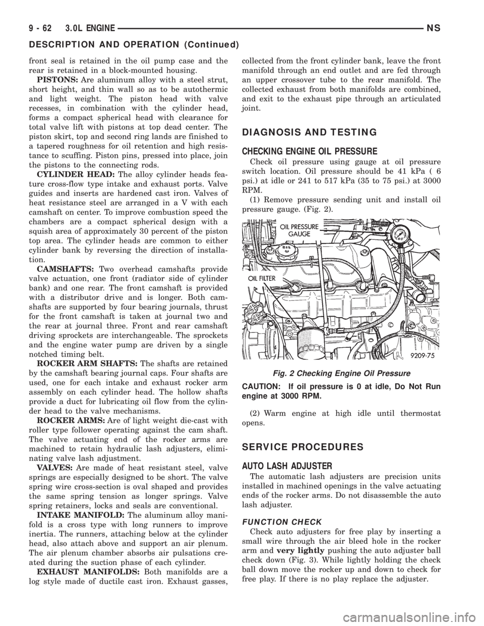
(1) Remove pressure sending unit and install oil
pressure gauge. (Fig. 2).
CAUTION: If oil pressure is 0 at idle, Do Not Run
engine at 3000 RPM.
(2) Warm engine at high idle until thermostat
opens.
SERVICE PROCEDURES
AUTO LASH ADJUSTER
The automatic lash adjusters are precision units
installed in machined openings in the valve actuating
ends of the rocker arms. Do not disassemble the auto
lash adjuster.
FUNCTION CHECK
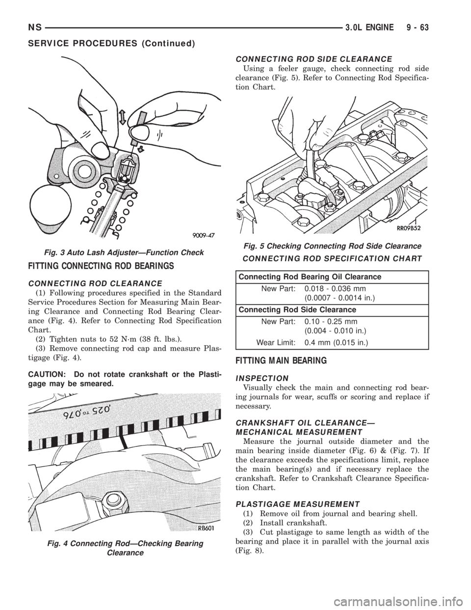
Check auto adjusters for free play by inserting a
small wire through the air bleed hole in the rocker
arm andvery lightlypushing the auto adjuster ball
check down (Fig. 3). While lightly holding the check
ball down move the rocker up and down to check for
free play. If there is no play replace the adjuster.
Fig. 2 Checking Engine Oil Pressure
9 - 62 3.0L ENGINENS
DESCRIPTION AND OPERATION (Continued)
Page 1113 of 1938
FITTING CONNECTING ROD BEARINGS
CONNECTING ROD CLEARANCE
(1) Following procedures specified in the Standard
Service Procedures Section for Measuring Main Bear-
ing Clearance and Connecting Rod Bearing Clear-
ance (Fig. 4). Refer to Connecting Rod Specification
Chart.
(2) Tighten nuts to 52 N´m (38 ft. lbs.).
(3) Remove connecting rod cap and measure Plas-
tigage (Fig. 4).
CAUTION: Do not rotate crankshaft or the Plasti-
gage may be smeared.
CONNECTING ROD SIDE CLEARANCE
Using a feeler gauge, check connecting rod side
clearance (Fig. 5). Refer to Connecting Rod Specifica-
tion Chart.
FITTING MAIN BEARING
INSPECTION
Visually check the main and connecting rod bear-
ing journals for wear, scuffs or scoring and replace if
necessary.
CRANKSHAFT OIL CLEARANCEÐ
MECHANICAL MEASUREMENT
Measure the journal outside diameter and the
main bearing inside diameter (Fig. 6) & (Fig. 7). If
the clearance exceeds the specifications limit, replace
the main bearing(s) and if necessary replace the
crankshaft. Refer to Crankshaft Clearance Specifica-
tion Chart.
PLASTIGAGE MEASUREMENT
(1) Remove oil from journal and bearing shell.
(2) Install crankshaft.
(3) Cut plastigage to same length as width of the
bearing and place it in parallel with the journal axis
(Fig. 8).
Fig. 3 Auto Lash AdjusterÐFunction Check
Fig. 4 Connecting RodÐChecking Bearing
Clearance
Fig. 5 Checking Connecting Rod Side Clearance
CONNECTING ROD SPECIFICATION CHART
Connecting Rod Bearing Oil Clearance
New Part: 0.018 - 0.036 mm
(0.0007 - 0.0014 in.)
Connecting Rod Side Clearance
New Part: 0.10 - 0.25 mm
(0.004 - 0.010 in.)
Wear Limit: 0.4 mm (0.015 in.)
NS3.0L ENGINE 9 - 63
SERVICE PROCEDURES (Continued)
Page 1115 of 1938
CHECKING CRANKSHAFT END PLAY
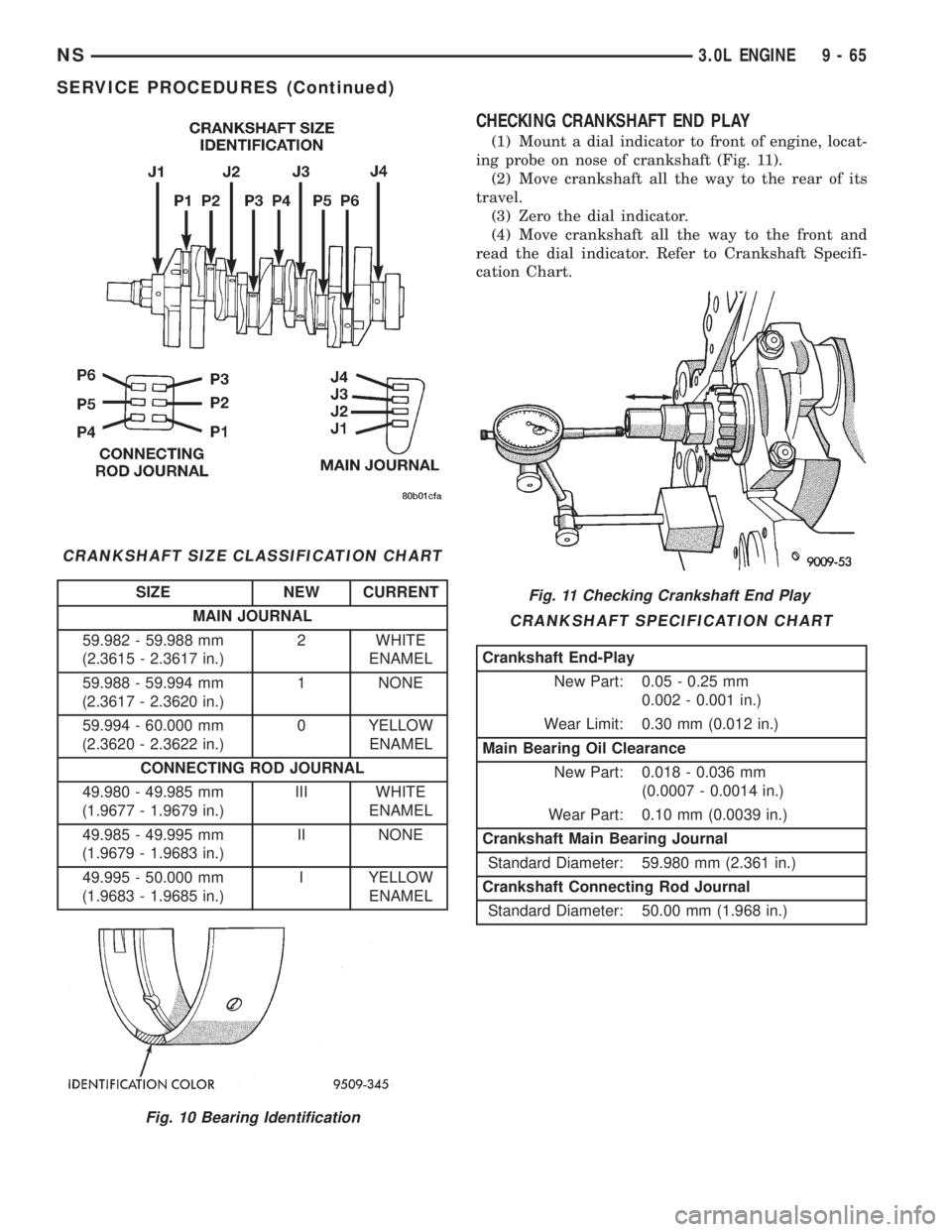
(1) Mount a dial indicator to front of engine, locat-
ing probe on nose of crankshaft (Fig. 11).
(2) Move crankshaft all the way to the rear of its
travel.
(3) Zero the dial indicator.
(4) Move crankshaft all the way to the front and
read the dial indicator. Refer to Crankshaft Specifi-
cation Chart.
CRANKSHAFT SIZE CLASSIFICATION CHART
SIZE NEW CURRENT
MAIN JOURNAL
59.982 - 59.988 mm
(2.3615 - 2.3617 in.)2 WHITE
ENAMEL
59.988 - 59.994 mm
(2.3617 - 2.3620 in.)1 NONE
59.994 - 60.000 mm
(2.3620 - 2.3622 in.)0 YELLOW
ENAMEL
CONNECTING ROD JOURNAL
49.980 - 49.985 mm
(1.9677 - 1.9679 in.)III WHITE
ENAMEL
49.985 - 49.995 mm
(1.9679 - 1.9683 in.)II NONE
49.995 - 50.000 mm
(1.9683 - 1.9685 in.)I YELLOW
ENAMEL
Fig. 10 Bearing Identification
Fig. 11 Checking Crankshaft End Play
CRANKSHAFT SPECIFICATION CHART
Crankshaft End-Play
New Part: 0.05 - 0.25 mm
0.002 - 0.001 in.)
Wear Limit: 0.30 mm (0.012 in.)
Main Bearing Oil Clearance
New Part: 0.018 - 0.036 mm
(0.0007 - 0.0014 in.)
Wear Part: 0.10 mm (0.0039 in.)
Crankshaft Main Bearing Journal
Standard Diameter: 59.980 mm (2.361 in.)
Crankshaft Connecting Rod Journal
Standard Diameter: 50.00 mm (1.968 in.)
NS3.0L ENGINE 9 - 65
SERVICE PROCEDURES (Continued)
Page 1116 of 1938
VALVE SERVICE RECONDITION
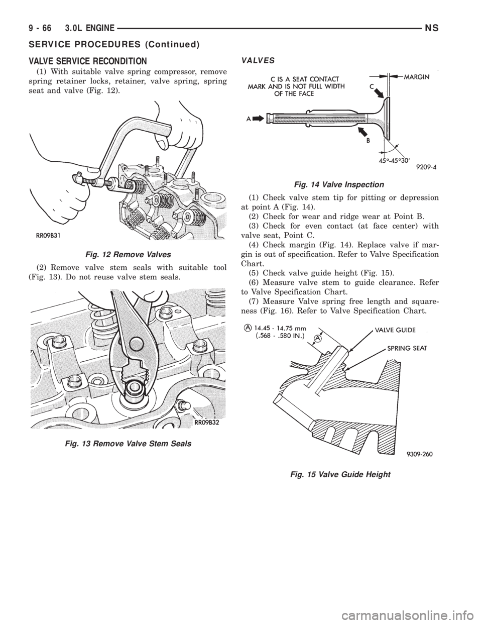
(1) With suitable valve spring compressor, remove
spring retainer locks, retainer, valve spring, spring
seat and valve (Fig. 12).
(2) Remove valve stem seals with suitable tool
(Fig. 13). Do not reuse valve stem seals.
VALVES
(1) Check valve stem tip for pitting or depression
at point A (Fig. 14).
(2) Check for wear and ridge wear at Point B.
(3) Check for even contact (at face center) with
valve seat, Point C.
(4) Check margin (Fig. 14). Replace valve if mar-
gin is out of specification. Refer to Valve Specification
Chart.
(5) Check valve guide height (Fig. 15).
(6) Measure valve stem to guide clearance. Refer
to Valve Specification Chart.
(7) Measure Valve spring free length and square-
ness (Fig. 16). Refer to Valve Specification Chart.
Fig. 12 Remove Valves
Fig. 13 Remove Valve Stem Seals
Fig. 14 Valve Inspection
Fig. 15 Valve Guide Height
9 - 66 3.0L ENGINENS
SERVICE PROCEDURES (Continued)