1996 CHRYSLER VOYAGER check engine
[x] Cancel search: check enginePage 1072 of 1938
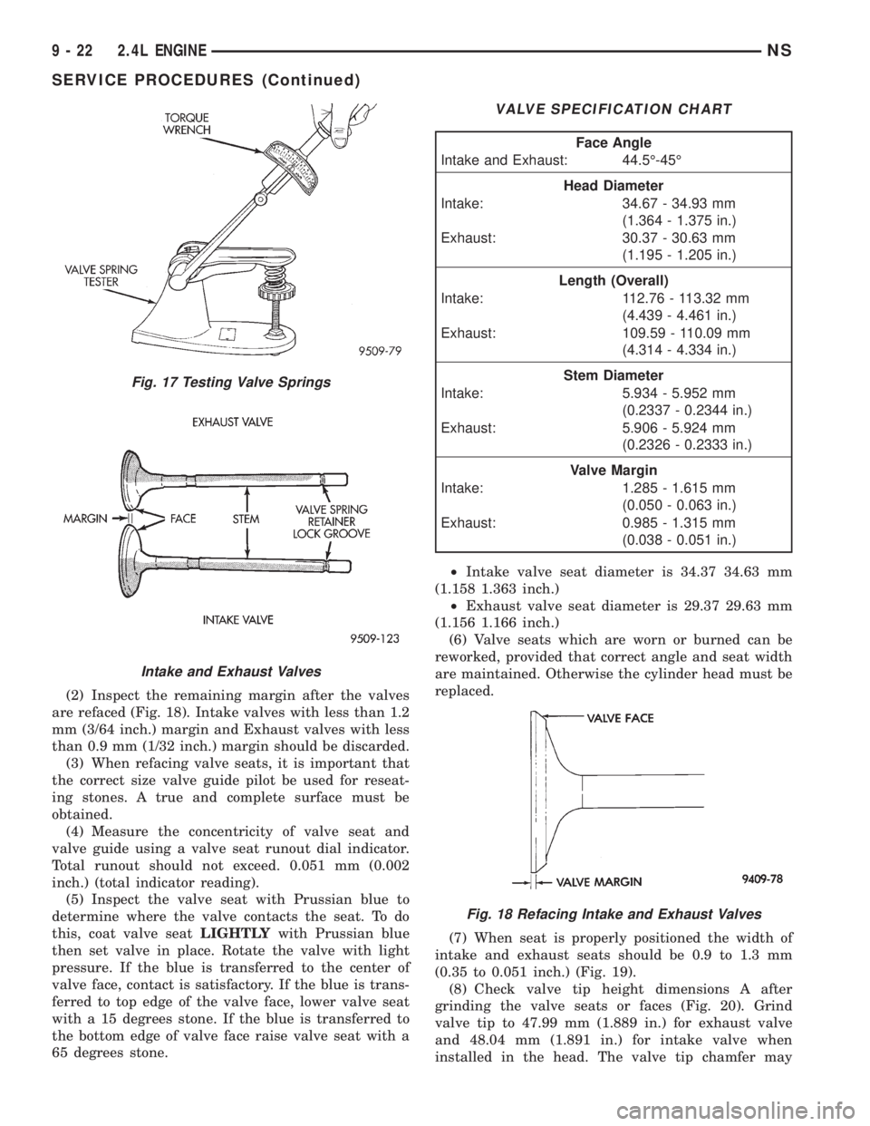
(2) Inspect the remaining margin after the valves
are refaced (Fig. 18). Intake valves with less than 1.2
mm (3/64 inch.) margin and Exhaust valves with less
than 0.9 mm (1/32 inch.) margin should be discarded.
(3) When refacing valve seats, it is important that
the correct size valve guide pilot be used for reseat-
ing stones. A true and complete surface must be
obtained.
(4) Measure the concentricity of valve seat and
valve guide using a valve seat runout dial indicator.
Total runout should not exceed. 0.051 mm (0.002
inch.) (total indicator reading).
(5) Inspect the valve seat with Prussian blue to
determine where the valve contacts the seat. To do
this, coat valve seatLIGHTLYwith Prussian blue
then set valve in place. Rotate the valve with light
pressure. If the blue is transferred to the center of
valve face, contact is satisfactory. If the blue is trans-
ferred to top edge of the valve face, lower valve seat
with a 15 degrees stone. If the blue is transferred to
the bottom edge of valve face raise valve seat with a
65 degrees stone.²Intake valve seat diameter is 34.37 34.63 mm
(1.158 1.363 inch.)
²Exhaust valve seat diameter is 29.37 29.63 mm
(1.156 1.166 inch.)
(6) Valve seats which are worn or burned can be
reworked, provided that correct angle and seat width
are maintained. Otherwise the cylinder head must be
replaced.
(7) When seat is properly positioned the width of
intake and exhaust seats should be 0.9 to 1.3 mm
(0.35 to 0.051 inch.) (Fig. 19).
(8) Check valve tip height dimensions A after
grinding the valve seats or faces (Fig. 20). Grind
valve tip to 47.99 mm (1.889 in.) for exhaust valve
and 48.04 mm (1.891 in.) for intake valve when
installed in the head. The valve tip chamfer may
Fig. 17 Testing Valve Springs
Intake and Exhaust Valves
VALVE SPECIFICATION CHART
Face Angle
Intake and Exhaust: 44.5É-45É
Head Diameter
Intake: 34.67 - 34.93 mm
(1.364 - 1.375 in.)
Exhaust: 30.37 - 30.63 mm
(1.195 - 1.205 in.)
Length (Overall)
Intake: 112.76 - 113.32 mm
(4.439 - 4.461 in.)
Exhaust: 109.59 - 110.09 mm
(4.314 - 4.334 in.)
Stem Diameter
Intake: 5.934 - 5.952 mm
(0.2337 - 0.2344 in.)
Exhaust: 5.906 - 5.924 mm
(0.2326 - 0.2333 in.)
Valve Margin
Intake: 1.285 - 1.615 mm
(0.050 - 0.063 in.)
Exhaust: 0.985 - 1.315 mm
(0.038 - 0.051 in.)
Fig. 18 Refacing Intake and Exhaust Valves
9 - 22 2.4L ENGINENS
SERVICE PROCEDURES (Continued)
Page 1073 of 1938
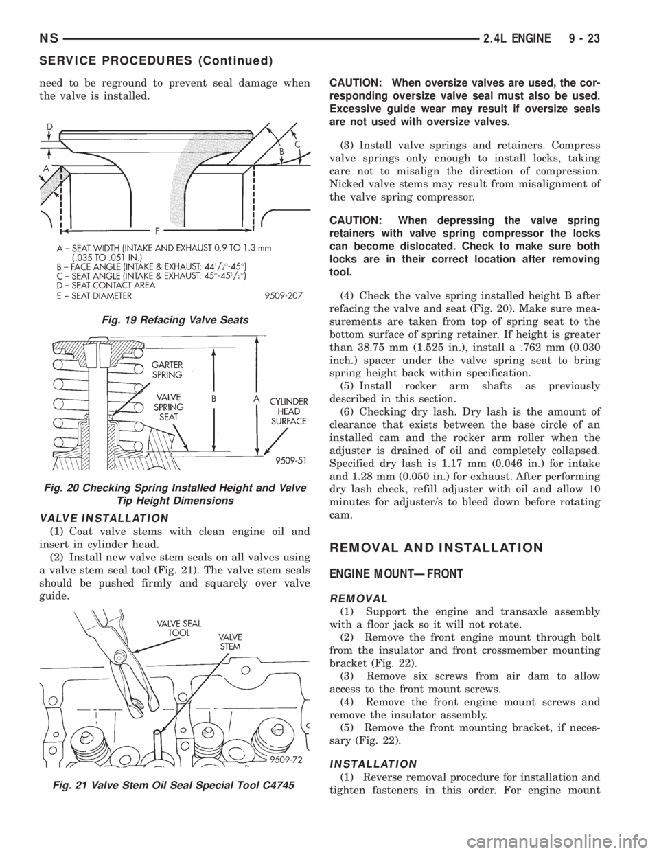
need to be reground to prevent seal damage when
the valve is installed.
VALVE INSTALLATION
(1) Coat valve stems with clean engine oil and
insert in cylinder head.
(2) Install new valve stem seals on all valves using
a valve stem seal tool (Fig. 21). The valve stem seals
should be pushed firmly and squarely over valve
guide.CAUTION: When oversize valves are used, the cor-
responding oversize valve seal must also be used.
Excessive guide wear may result if oversize seals
are not used with oversize valves.
(3) Install valve springs and retainers. Compress
valve springs only enough to install locks, taking
care not to misalign the direction of compression.
Nicked valve stems may result from misalignment of
the valve spring compressor.
CAUTION: When depressing the valve spring
retainers with valve spring compressor the locks
can become dislocated. Check to make sure both
locks are in their correct location after removing
tool.
(4) Check the valve spring installed height B after
refacing the valve and seat (Fig. 20). Make sure mea-
surements are taken from top of spring seat to the
bottom surface of spring retainer. If height is greater
than 38.75 mm (1.525 in.), install a .762 mm (0.030
inch.) spacer under the valve spring seat to bring
spring height back within specification.
(5) Install rocker arm shafts as previously
described in this section.
(6) Checking dry lash. Dry lash is the amount of
clearance that exists between the base circle of an
installed cam and the rocker arm roller when the
adjuster is drained of oil and completely collapsed.
Specified dry lash is 1.17 mm (0.046 in.) for intake
and 1.28 mm (0.050 in.) for exhaust. After performing
dry lash check, refill adjuster with oil and allow 10
minutes for adjuster/s to bleed down before rotating
cam.
REMOVAL AND INSTALLATION
ENGINE MOUNTÐFRONT
REMOVAL
(1) Support the engine and transaxle assembly
with a floor jack so it will not rotate.
(2) Remove the front engine mount through bolt
from the insulator and front crossmember mounting
bracket (Fig. 22).
(3) Remove six screws from air dam to allow
access to the front mount screws.
(4) Remove the front engine mount screws and
remove the insulator assembly.
(5) Remove the front mounting bracket, if neces-
sary (Fig. 22).
INSTALLATION
(1) Reverse removal procedure for installation and
tighten fasteners in this order. For engine mount
Fig. 19 Refacing Valve Seats
Fig. 20 Checking Spring Installed Height and Valve
Tip Height Dimensions
Fig. 21 Valve Stem Oil Seal Special Tool C4745
NS2.4L ENGINE 9 - 23
SERVICE PROCEDURES (Continued)
Page 1079 of 1938
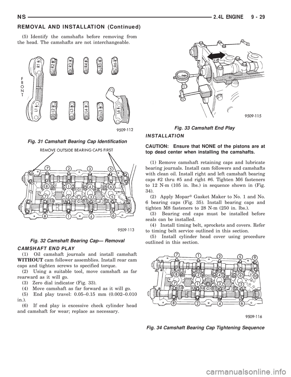
(5) Identify the camshafts before removing from
the head. The camshafts are not interchangeable.
CAMSHAFT END PLAY
(1) Oil camshaft journals and install camshaft
WITHOUTcam follower assemblies. Install rear cam
caps and tighten screws to specified torque.
(2) Using a suitable tool, move camshaft as far
rearward as it will go.
(3) Zero dial indicator (Fig. 33).
(4) Move camshaft as far forward as it will go.
(5) End play travel: 0.05±0.15 mm (0.002±0.010
in.).
(6) If end play is excessive check cylinder head
and camshaft for wear; replace as necessary.
INSTALLATION
CAUTION: Ensure that NONE of the pistons are at
top dead center when installing the camshafts.
(1) Remove camshaft retaining caps and lubricate
bearing journals. Install cam followers and camshafts
with clean oil. Install right and left camshaft bearing
caps #2 thru #5 and right #6. Tighten M6 fasteners
to 12 N´m (105 in. lbs.) in sequence shown in (Fig.
34).
(2) Apply MopartGasket Maker to No. 1 and No.
6 bearing caps (Fig. 35). Install bearing caps and
tighten M8 fasteners to 28 N´m (250 in. lbs.).
(3) Bearing end caps must be installed before
seals can be installed.
(4) Install timing belt, sprockets and covers. Refer
to timing belt service outlined in this section.
(5) Install cylinder head cover using procedure
outlined in this section.Fig. 31 Camshaft Bearing Cap Identification
Fig. 32 Camshaft Bearing CapÐ Removal
Fig. 33 Camshaft End Play
Fig. 34 Camshaft Bearing Cap Tightening Sequence
NS2.4L ENGINE 9 - 29
REMOVAL AND INSTALLATION (Continued)
Page 1084 of 1938
CYLINDER HEAD
REMOVAL
(1) Perform fuel system pressure release proce-
durebefore attempting any repairs.Refer to
Group 14, Fuel System for procedure.
(2) Disconnect negative battery cable. Drain cool-
ing system. Refer to Group 7, Cooling System for pro-
cedure.
(3) Remove air cleaner and disconnect all vacuum
lines, electrical wiring and fuel lines from throttle
body.
(4) Remove throttle linkage. Refer to Group 14,
Fuel System for procedures
(5) Remove accessory drive belts. Refer to Group
7, Cooling System for procedure.
(6) Remove power brake vacuum hose from intake
manifold.
(7) Raise vehicle and remove exhaust pipe from
manifold.(8) Remove power steering pump assembly and
set aside.
(9) Disconnect coil pack wiring connector and
remove coil pack and plug wires from engine.
(10) Remove cam sensor and fuel injectors wiring
connectors.
(11) Remove timing belt and camshaft sprocket.
Refer to procedure outlined in this section.
(12) Remove timing belt idler pulley and rear tim-
ing belt cover.
(13) Remove cylinder head cover using procedure
outlined in this section.
(14) Remove camshafts and cam followers. Refer to
procedures outlined in this section for procedures.
(15) Remove cylinder head bolts and remove cyl-
inder head from engine block.
(16) Inspect and clean cylinder head. Refer to
Cleaning and Inspection outlined in this section for
procedures.
INSTALLATION
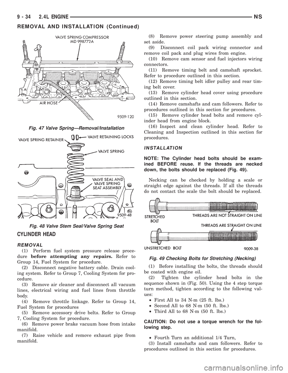
NOTE: The Cylinder head bolts should be exam-
ined BEFORE reuse. If the threads are necked
down, the bolts should be replaced (Fig. 49).
Necking can be checked by holding a scale or
straight edge against the threads. If all the threads
do not contact the scale the bolt should be replaced.
(1) Before installing the bolts, the threads should
be coated with engine oil.
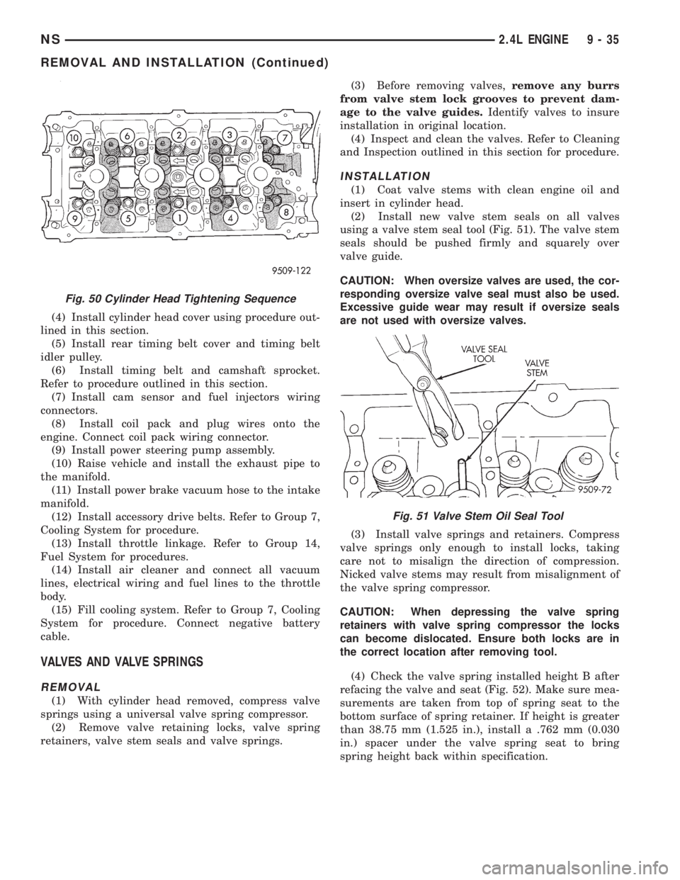
(2) Tighten the cylinder head bolts in the
sequence shown in (Fig. 50). Using the 4 step torque
turn method, tighten according to the following val-
ues:
²First All to 34 N´m (25 ft. lbs.)
²Second All to 68 N´m (50 ft. lbs.)
²Third All to 68 N´m (50 ft. lbs.)
CAUTION: Do not use a torque wrench for the fol-
lowing step.
²Fourth Turn an additional 1/4 Turn,
(3) Install camshafts and cam followers. Refer to
procedures outlined in this section for procedures.
Fig. 47 Valve SpringÐRemoval/Installation
Fig. 48 Valve Stem Seal/Valve Spring Seat
Fig. 49 Checking Bolts for Stretching (Necking)
9 - 34 2.4L ENGINENS
REMOVAL AND INSTALLATION (Continued)
Page 1085 of 1938
(4) Install cylinder head cover using procedure out-
lined in this section.
(5) Install rear timing belt cover and timing belt
idler pulley.
(6) Install timing belt and camshaft sprocket.
Refer to procedure outlined in this section.
(7) Install cam sensor and fuel injectors wiring
connectors.
(8) Install coil pack and plug wires onto the
engine. Connect coil pack wiring connector.
(9) Install power steering pump assembly.
(10) Raise vehicle and install the exhaust pipe to
the manifold.
(11) Install power brake vacuum hose to the intake
manifold.
(12) Install accessory drive belts. Refer to Group 7,
Cooling System for procedure.
(13) Install throttle linkage. Refer to Group 14,
Fuel System for procedures.
(14) Install air cleaner and connect all vacuum
lines, electrical wiring and fuel lines to the throttle
body.
(15) Fill cooling system. Refer to Group 7, Cooling
System for procedure. Connect negative battery
cable.
VALVES AND VALVE SPRINGS
REMOVAL
(1) With cylinder head removed, compress valve
springs using a universal valve spring compressor.
(2) Remove valve retaining locks, valve spring
retainers, valve stem seals and valve springs.(3) Before removing valves,remove any burrs
from valve stem lock grooves to prevent dam-
age to the valve guides.Identify valves to insure
installation in original location.
(4) Inspect and clean the valves. Refer to Cleaning
and Inspection outlined in this section for procedure.
INSTALLATION
(1) Coat valve stems with clean engine oil and
insert in cylinder head.
(2) Install new valve stem seals on all valves
using a valve stem seal tool (Fig. 51). The valve stem
seals should be pushed firmly and squarely over
valve guide.
CAUTION: When oversize valves are used, the cor-
responding oversize valve seal must also be used.
Excessive guide wear may result if oversize seals
are not used with oversize valves.
(3) Install valve springs and retainers. Compress
valve springs only enough to install locks, taking
care not to misalign the direction of compression.
Nicked valve stems may result from misalignment of
the valve spring compressor.
CAUTION: When depressing the valve spring
retainers with valve spring compressor the locks
can become dislocated. Ensure both locks are in
the correct location after removing tool.
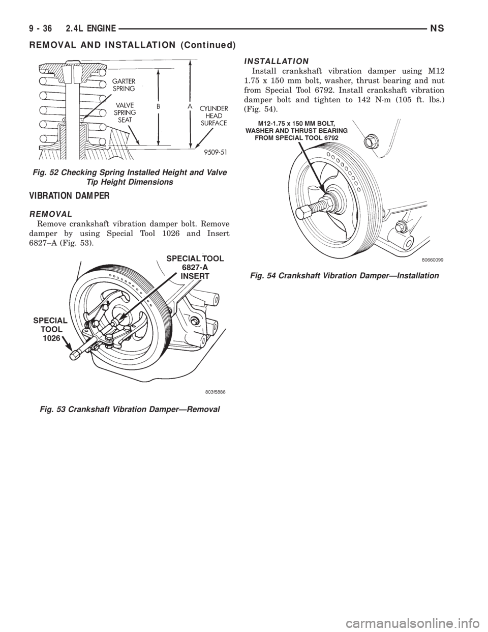
(4) Check the valve spring installed height B after
refacing the valve and seat (Fig. 52). Make sure mea-
surements are taken from top of spring seat to the
bottom surface of spring retainer. If height is greater
than 38.75 mm (1.525 in.), install a .762 mm (0.030
in.) spacer under the valve spring seat to bring
spring height back within specification.
Fig. 50 Cylinder Head Tightening Sequence
Fig. 51 Valve Stem Oil Seal Tool
NS2.4L ENGINE 9 - 35
REMOVAL AND INSTALLATION (Continued)
Page 1086 of 1938
VIBRATION DAMPER
REMOVAL
Remove crankshaft vibration damper bolt. Remove
damper by using Special Tool 1026 and Insert
6827±A (Fig. 53).
INSTALLATION
Install crankshaft vibration damper using M12
1.75 x 150 mm bolt, washer, thrust bearing and nut
from Special Tool 6792. Install crankshaft vibration
damper bolt and tighten to 142 N´m (105 ft. lbs.)
(Fig. 54).
Fig. 52 Checking Spring Installed Height and Valve
Tip Height Dimensions
Fig. 53 Crankshaft Vibration DamperÐRemoval
Fig. 54 Crankshaft Vibration DamperÐInstallation
9 - 36 2.4L ENGINENS
REMOVAL AND INSTALLATION (Continued)
Page 1097 of 1938
(7) Install main bearing bedplate to engine block
bolts 11, 17 and 20 finger tight. Tighten these bolts
down together until the bedplate contacts the cylin-
der block.
(8) To ensure correct thrust bearing alignment per-
form the following steps:
²Step 1: Rotate crankshaft until number 4 pis-
ton is at TDC.
²Step 2: Move crankshaft rearward to limits of
travel.
²Step 3: Then, move crankshaft forward to lim-
its of travel.
²Step 4: Wedge an appropraite tool between the
rear of the cylinder block(NOT BED PLATE)and
the rear crankshaft counterweight. This will hold the
crankshaft in it's furthest forward position.
²Step 5: Install and tighten bolts (1-10) in
sequence shown in (Fig. 84) to 41 Nzm (30 ft. lbs.).
²Step 6: Remove wedge tool used to hold crank-
shaft.
(9) Tighten bolts (1-10) again to 41 Nzm (30 ft. lbs)
+ 1/4 turn in sequence shown in (Fig. 84).
(10) Install main bearing bedplate to engine block
bolts (11-20), and torque each bolt to 28 Nzm (20 ft.
lbs.) in sequence shown in (Fig. 84).
(11) After the main bearing bedplate is installed,
check the crankshaft turning torque. The turning
torque should not exceed 5.6 Nzm (50 in. lbs.).
OIL FILTER
CAUTION: When servicing the oil filter avoid
deforming the filter can by installing the remove/in-
stall tool band strap against the can to base lock
seam. The lock seam joining the can to the base is
reinforced by the base plate.(1) Turn counterclockwise to remove.
(2) To install, lubricate new filter gasket. Check
filter mounting surface. The surface must be smooth,
flat and free of debris or old pieces of rubber. Screw
filter on until the gasket contacts base. Tighten to 21
N´m (15 ft. lbs.).
OIL PUMP
REMOVAL
(1) Disconnect negative cable from battery.
(2) Remove Timing Belt. Refer to procedure out-
lined in this section.
(3) Remove Oil Pan. Refer to procedure outlined in
this section.
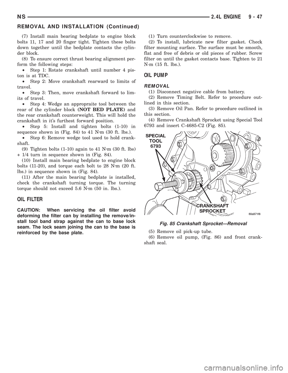
(4) Remove Crankshaft Sprocket using Special Tool
6793 and insert C-4685-C2 (Fig. 85).
(5) Remove oil pick-up tube.
(6) Remove oil pump, (Fig. 86) and front crank-
shaft seal.
Fig. 85 Crankshaft SprocketÐRemoval
NS2.4L ENGINE 9 - 47
REMOVAL AND INSTALLATION (Continued)
Page 1100 of 1938
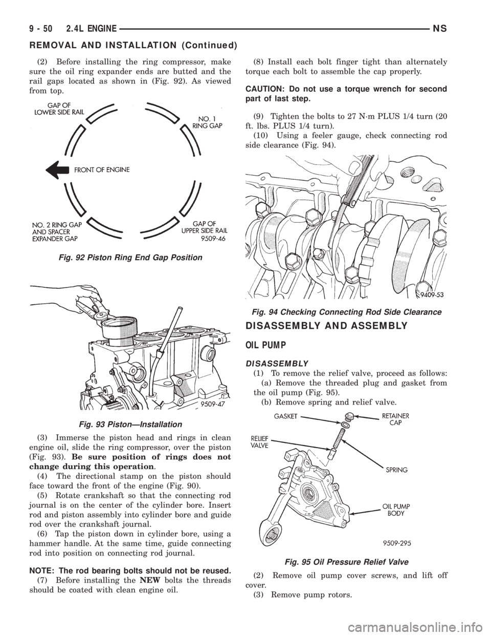
(2) Before installing the ring compressor, make
sure the oil ring expander ends are butted and the
rail gaps located as shown in (Fig. 92). As viewed
from top.
(3) Immerse the piston head and rings in clean
engine oil, slide the ring compressor, over the piston
(Fig. 93).Be sure position of rings does not
change during this operation.
(4) The directional stamp on the piston should
face toward the front of the engine (Fig. 90).
(5) Rotate crankshaft so that the connecting rod
journal is on the center of the cylinder bore. Insert
rod and piston assembly into cylinder bore and guide
rod over the crankshaft journal.
(6) Tap the piston down in cylinder bore, using a
hammer handle. At the same time, guide connecting
rod into position on connecting rod journal.
NOTE: The rod bearing bolts should not be reused.
(7) Before installing theNEWbolts the threads
should be coated with clean engine oil.(8) Install each bolt finger tight than alternately
torque each bolt to assemble the cap properly.
CAUTION: Do not use a torque wrench for second
part of last step.
(9) Tighten the bolts to 27 N´m PLUS 1/4 turn (20
ft. lbs. PLUS 1/4 turn).
(10) Using a feeler gauge, check connecting rod
side clearance (Fig. 94).
DISASSEMBLY AND ASSEMBLY
OIL PUMP
DISASSEMBLY
(1) To remove the relief valve, proceed as follows:
(a) Remove the threaded plug and gasket from
the oil pump (Fig. 95).
(b) Remove spring and relief valve.
(2) Remove oil pump cover screws, and lift off
cover.
(3) Remove pump rotors.
Fig. 92 Piston Ring End Gap Position
Fig. 93 PistonÐInstallation
Fig. 94 Checking Connecting Rod Side Clearance
Fig. 95 Oil Pressure Relief Valve
9 - 50 2.4L ENGINENS
REMOVAL AND INSTALLATION (Continued)