1996 ACURA RL KA9 check oil
[x] Cancel search: check oilPage 605 of 1954

PGM-FI Syste m
Crankshaf t Position/Cylinde r Positio n (CKP/CYP ) Senso r
The sca n too l indicate s Diagnosti c Troubl e Cod e (DTC ) P0335 : A malfunctio n in th e circui t o f th e Crankshaf t
Positio n (CKP ) senso r 1 .
Th e sca n too l indicate s Diagnosti c Troubl e Cod e (DTC ) P0336 : A n intermitten t interruptio n proble m of the
Crankshaf t Positio n (CKP ) senso r 1 .
Th e sca n too l indicate s Diagnosti c Troubl e Cod e (DTC ) P1337 : A malfunctio n i n th e circui t o f th e Crankshaf t
Positio n (CKP ) senso r 2 .
Th e sca n too l indicate s Diagnosti c Troubl e Cod e (DTC ) P1336 : A n intermitten t interruptio n proble m o f th e
Crankshaf t Positio n (CKP ) senso r 2 .
Th e sca n too l indicate s Diagnosti c Troubl e Cod e (DTC ) P1381 : A n intermitten t interruptio n proble m o f th e
Cylinde r Positio n (CYP ) senso r 1 .
Th e sca n too l indicate s Diagnosti c Troubl e Cod e (DTC ) P1382 : A malfunctio n in th e circui t o f th e Cylinde r Positio r
(CYP ) senso r 1 .
Th e sca n too l indicate s Diagnosti c Troubl e Cod e (DTC ) P1386 : A n intermitten t interruptio n proble m of the
Cylinde r Positio n (CYP ) senso r 2 .
Th e sca n too l indicate s Diagnosti c Troubl e Cod e (DTC ) P1387 : A malfunctio n in th e circui t o f th e Cylinde r Positio n
(CYP) senso r 2 .
Proble m verification :
1 . D o th e PC M Rese t Procedure .
2 . Star t th e engine .
I s DT C P0335 , P0336 , P1337 , P1336 ,
P1381 , P1382 , P138 6 and/o r P138 7
indicated ?
Chec k fo r a n ope n in th e CKP/CY P
sensor:1. Tur n th e ignitio n switc h OFF .2. Disconnec t th e CKP/CY P 8 P
connector .
3 . Measur e resistanc e betwee n
the terminal s o f th e indicate dsensor (se e table) .
I s ther e 65 0 - 85 0
YES
Chec k fo r a shor t i n th e CKP/CY Psensor:Check fo r continuit y t o bod yground o n bot h terminal s o f th eindicate d sensor . CY
P PICK-U P
COI L 2
CY P PICK-U P
COI L 1
Intermitten t failure , syste m is O K
a t thi s time . Chec k fo r poo r con -
nection s o r loos e wire s a t C251 ,
C25 5 (locate d a t lef t shoc k tower) ,
C13 0 (CKP/CYP ) senso r an d PCM .
Replac e th e CKP/CY P senso r (se e
sectio n 6 ).
CKP/CYP SENSO R 8 P CONNECTO R
Termina l sid e o f mal e terminal s
(T o pag e 11-107 )
NO
YE S
NO
CK P PICK-U P
COI L 1CK P PICK-U PCOIL 2
Th e CK P Senso r determine s timin g fo r injectio n an d ignitio n o f eac h cylinde r an d als o detect s engin e speed .
Th e CY P Senso r detect s th e positio n o f No . 1 cylinde r fo r sequentia l injectio n t o eac h cylinder . Th e CKP/CY P Senso r i s
installe d behin d th e fron t camshaf t pulley .
— Th e MI L ha s bee n reporte d on .
— DT C P0335 , P0336 , P133 7
P1336 , P1381 , P1382 , P138 6
and/o r P138 7 ar e stored .
ProCarManuals.com
Page 634 of 1954

Fuel Supply System
Injectors (cont'd)
13. Slide new cushion rings onto the injectors.
14. Coat new O-rings with clean engine oil, and put them on the injectors.
15. Insert the injectors into the fuel rail first.
16. Coat new seal rings with clean engine oil and press them into the intake manifold.
17. To prevent damage to the O-ring, install the injectors in the fuel rail first, then install them in the intake manifold.
FUEL
RAILS
18. Install and tighten the retainer nuts.
19. Connect the 3P connector to the MAP sensor.
20. Connect the fuel hose to the fuel rail.
21. Connect the vacuum pipe.
22. Connect the vacuum hose and fuel return hose to the fuel pressure regulator.
23. Install the connectors on the injectors.
24. Connect the PCV valve.
25. Turn the ignition switch ON (II), but do not operate the starter. After the fuel pump runs for approximately 2 seconds,
the fuel pressure in the fuel line rises. Repeat this two or three times, then check whether there is any fuel leakage.
26. Install the engine cover.
27. Install the strut bar.ProCarManuals.com
Page 794 of 1954
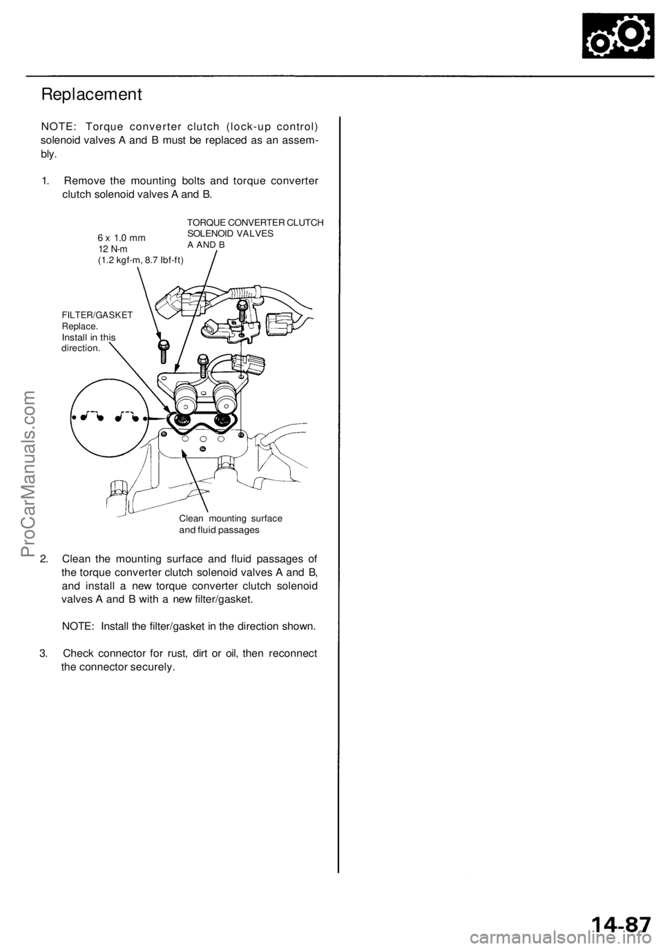
Replacement
NOTE: Torque converter clutch (lock-up control)
solenoid valves A and B must be replaced as an assem-
bly.
1. Remove the mounting bolts and torque converter
clutch solenoid valves A and B.
6 x 1.0 mm
12 N-m
(1.2 kgf-m, 8.7 Ibf-ft)
TORQUE CONVERTER CLUTCH
SOLENOID VALVES
A AND B
FILTER/GASKET
Replace.
Install in this
direction.
Clean mounting surface
and fluid passages
2. Clean the mounting surface and fluid passages of
the torque converter clutch solenoid valves A and B,
and install a new torque converter clutch solenoid
valves A and B with a new filter/gasket.
NOTE: Install the filter/gasket in the direction shown.
3. Check connector for rust, dirt or oil, then reconnect
the connector securely.ProCarManuals.com
Page 915 of 1954

Maintenance
Differential Oil
NOTE: Check the differential oil with engine OFF, and
the vehicle on level ground.
1. Remove the oil filler plug, then check the level and
condition of the oil.
WASHER
Replace.
Proper Lever
OIL FILLER PLUG
44 N-m (4.5 kgf-m, 33 Ibf-ft)
WASHER Replace.
2. The oil level must be up to the fill hole. If it is below
the hole, add oil until it runs out, then reinstall the
oil filler plug with a new washer.
3. If the differential oil is dirty, remove the drain plug,
and drain the oil.
DRAIN PLUG
39 N-m (4.0 kgf-m, 29 Ibf-ft)
WASHER Replace.
OIL FILLER PLUG
44 N-m (4.5 kgf-m, 33 Ibf-ft)
4. Reinstall the drain plug with a new washer, and refill
the differential with the recommended oil to the
proper level.
NOTE:
The drain plug washer should be replaced at every
oil change.
Clean the drain plug before reinstalling.
5. Reinstall the oil filler plug with a new washer.
Oil Capacity
1.05 (1.11 US qt, 0.92 Imp qt) at oil change
1.10 (1.16 US qt, 0.97 Imp qt) at overhaul
Recommended oil:
Hypoid gear oil
API Classification GL4 or GL5
viscosity:
SAE 90 above 0°F (-18°C)
SAE 80 W - 90 below 0°F (-18°C)ProCarManuals.com
Page 1037 of 1954
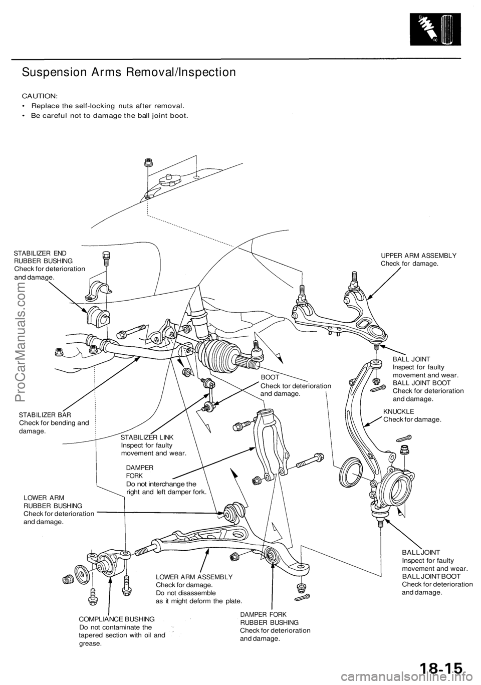
Suspension Arms Removal/Inspection
CAUTION:
• Replace the self-locking nuts after removal.
• Be careful not to damage the ball joint boot.
STABILIZER END
RUBBER BUSHING
Check for deterioration
and damage.
UPPER ARM ASSEMBLY
Check for damage.
STABILIZER BAR
Check for bending and
damage.
BALL JOINT
Inspect for faulty
movement and wear.
BALL JOINT BOOT
Check for deterioration
and damage.
KNUCKLE
Check for damage.
LOWER ARM
RUBBER BUSHING
Check for deterioration
and damage.
BALL JOINT
Inspect for faulty
movement and wear.
BALL JOINT BOOT
Check for deterioration
and damage.
COMPLIANCE BUSHING
Do not contaminate the
tapered section with oil and
grease.
DAMPER FORK
RUBBER BUSHING
Check for deterioration
and damage.
LOWER ARM ASSEMBLY
Check for damage.
Do not disassemble
as it might deform the plate.
DAMPER
FORK
Do not interchange the
right and left damper fork.
STABILIZER LINK
Inspect for faulty
movement and wear.
BOOT
Check tor deterioration
and damage.ProCarManuals.com
Page 1039 of 1954
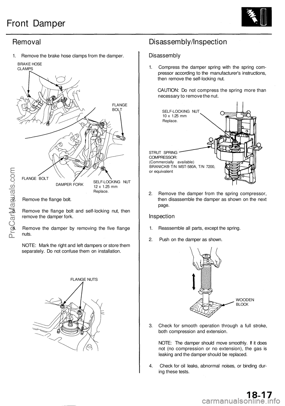
Front Damper
Removal
1. Remove the brake hose clamps from the damper.
BRAKE HOSE
CLAMPS
FLANGE
BOLT
FLANGE BOLT
DAMPER FORK
SELF-LOCKING NUT
12 x
1.25
mm
Replace.
2. Remove the flange bolt.
3. Remove the flange bolt and self-locking nut, then
remove the damper fork.
4. Remove the damper by removing the five flange
nuts.
NOTE: Mark the right and left dampers or store them
separately. Do not confuse them on installation.
FLANGE NUTS
Disassembly/Inspection
Disassembly
1. Compress the damper spring with the spring com-
pressor according to the manufacturer's instructions,
then remove the self-locking nut.
CAUTION: Do not compress the spring more than
necessary to remove the nut.
SELF-LOCKING NUT
10 x
1.25
mm
Replace.
STRUT SPRING
COMPRESSOR:
(Commercially available)
BRANICK® T/N MST-580A, T/N 7200,
or equivalent
2. Remove the damper from the spring compressor,
then disassemble the damper as shown on the next
page.
Inspection
1. Reassemble all parts, except the spring.
2. Push on the damper as shown.
WOODEN
BLOCK
3. Check for smooth operation through a full stroke,
both compression and extension.
NOTE: The damper should move smoothly. If it does
not (no compression or no extension), the gas is
leaking and the damper should be replaced.
4. Check for oil leaks, abnormal noises, or binding dur-
ing these tests.ProCarManuals.com
Page 1046 of 1954
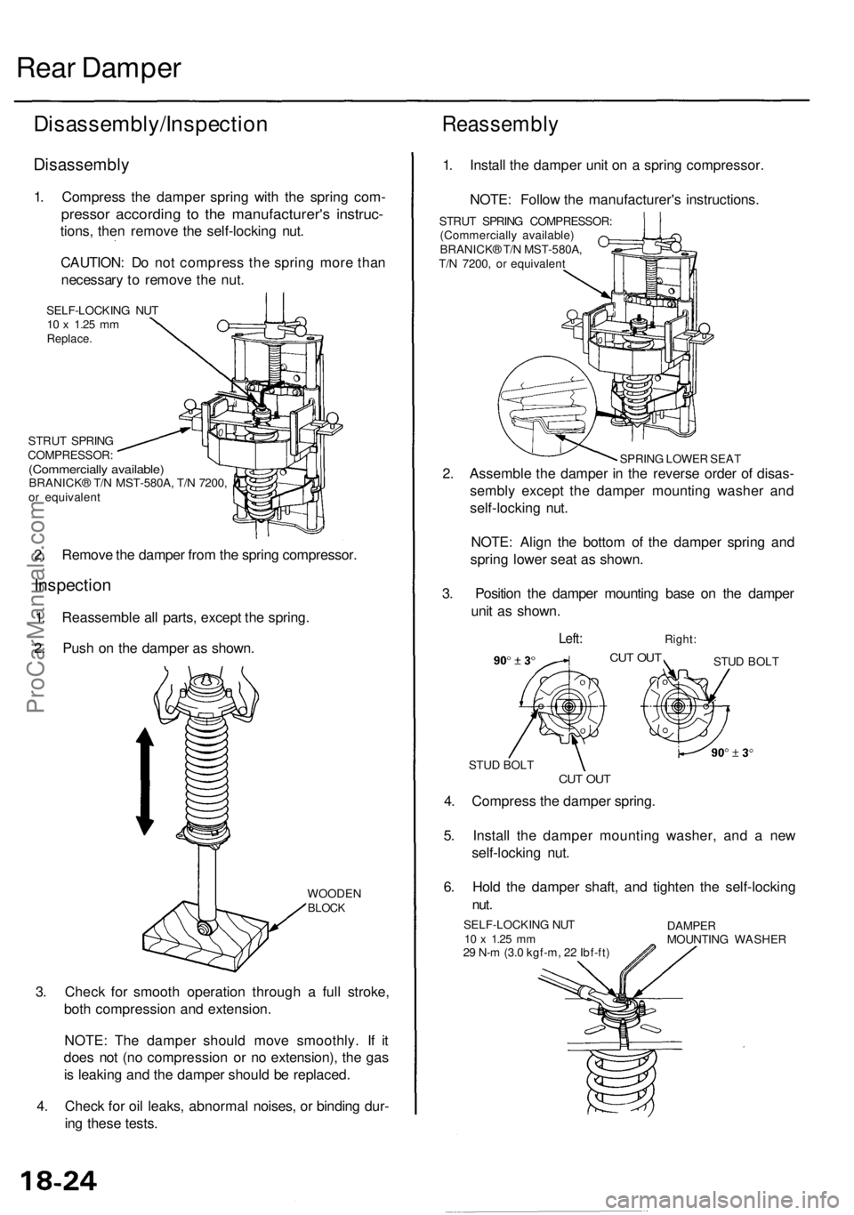
Rear Damper
Disassembly/Inspection
Disassembly
1. Compress the damper spring with the spring com-
pressor according to the manufacturer's instruc-
tions, then remove the self-locking nut.
CAUTION: Do not compress the spring more than
necessary to remove the nut.
SELF-LOCKING NUT
10 x
1.25
mm
Replace.
STRUT SPRING
COMPRESSOR:
(Commercially available)
BRANICK® T/N MST-580A, T/N 7200,
or equivalent
2. Remove the damper from the spring compressor.
Inspection
1. Reassemble all parts, except the spring.
2. Push on the damper as shown.
WOODEN
BLOCK
3. Check for smooth operation through a full stroke,
both compression and extension.
NOTE: The damper should move smoothly. If it
does not (no compression or no extension), the gas
is leaking and the damper should be replaced.
4. Check for oil leaks, abnormal noises, or binding dur-
ing these tests.
Reassembly
1. Install the damper unit on a spring compressor.
NOTE: Follow the manufacturer's instructions.
STRUT SPRING COMPRESSOR:
(Commercially available)
BRANICK® T/N MST-580A,
T/N 7200, or equivalent
SPRING LOWER SEAT
2. Assemble the damper in the reverse order of disas-
sembly except the damper mounting washer and
self-locking nut.
NOTE: Align the bottom of the damper spring and
spring lower seat as shown.
3. Position the damper mounting base on the damper
unit as shown.
Left:
Right:
CUT OUT
STUD BOLT
CUT OUT
STUD BOLT
4. Compress the damper spring.
5. Install the damper mounting washer, and a new
self-locking nut.
6. Hold the damper shaft, and tighten the self-locking
nut.
SELF-LOCKING NUT
10 x
1.25
mm
29 N-m (3.0 kgf-m, 22 Ibf-ft)
DAMPER
MOUNTING WASHERProCarManuals.com
Page 1497 of 1954
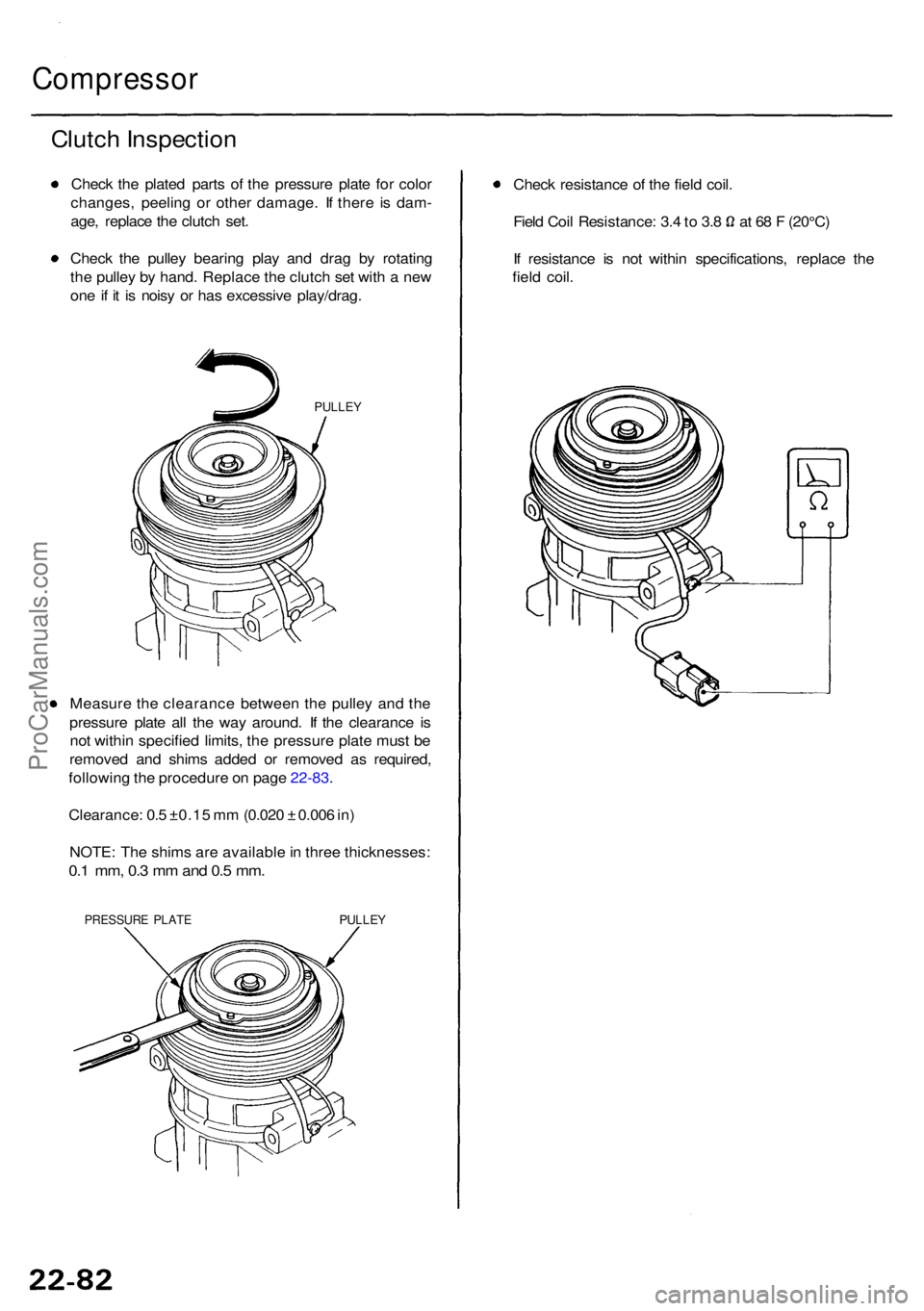
Compressor
Clutch Inspectio n
Check th e plate d part s o f th e pressur e plat e fo r colo r
changes , peelin g o r othe r damage . I f ther e i s dam -
age , replac e th e clutc h set .
Chec k th e pulle y bearin g pla y an d dra g b y rotatin g
th e pulle y b y hand . Replac e th e clutc h se t wit h a ne w
on e if i t i s nois y o r ha s excessiv e play/drag .
PULLEY
Measur e th e clearanc e betwee n th e pulle y an d th e
pressur e plat e al l th e wa y around . I f th e clearanc e i s
no t withi n specifie d limits , th e pressur e plat e mus t b e
remove d an d shim s adde d o r remove d a s required ,
followin g th e procedur e o n pag e 22-83 .
Clearance : 0. 5 ±0.1 5 m m (0.02 0 ± 0.00 6 in )
NOTE : Th e shim s ar e availabl e in thre e thicknesses :
0.1 mm , 0. 3 m m an d 0. 5 mm .
PRESSUR E PLAT EPULLE Y
Check resistanc e o f th e fiel d coil .
Field Coi l Resistance : 3. 4 to 3. 8 a t 6 8 F (20°C )
I f resistanc e i s no t withi n specifications , replac e th e
fiel d coil .
ProCarManuals.com