Page 259 of 1954

Navigation Syste m
Sympto m Troubleshootin g (cont'd )
8. Chec k fo r continuit y betwee n navigatio n uni t connec -
tor B (14P ) termina l No . 5 an d th e audi o uni t connec -
tor A (20P ) termina l No . 13 .
NAVIGATIO N UNIT CONNECTO R B (14P>
RG L (+ ) (WHT )
AUDIO UNI T CONNECTO R A (20P )
Wire sid e o f femal e terminal s
Is there continuity?
YES—G o to ste p 9 .
NO—Ther e is a n ope n i n th e circui t betwee n th e navi -
gatio n uni t an d audi o unit . Chec k fo r poo r connec -
tions o r loos e terminal s a t th e audi o an d navigatio n
units. I f a poo r connectio n o r loos e termina l i s found ,
replace th e affecte d shielde d harness .
9. Chec k fo r continuit y betwee n navigatio n uni t connec -
tor B (14P ) termina l No . 1 2 an d th e audi o uni t connec -
tor B (14P ) termina l No . 8 .
NAVIGATIO N UNI T CONNECTO R B (14P )
Wire sid e o f femal e terminal s
Is there continuity?
YES—G o to ste p 10 .
NO—Ther e is a n ope n i n th e circui t betwee n th e navi -
gatio n uni t an d th e audi o unit . Chec k fo r poo r con -
nection s o r loos e terminal s a t th e audi o an d naviga -
tion units . I f a poo r connectio n o r loos e termina l i s
found , replac e th e affecte d shielde d harness .
10. Substitut e a known-goo d audi o unit , an d recheck .
Is the system OK?
YES—Replac e th e audi o unit .
NO—Replac e th e navigatio n uni t
(see pag e 23-53 )
ProCarManuals.com
Page 1366 of 1954

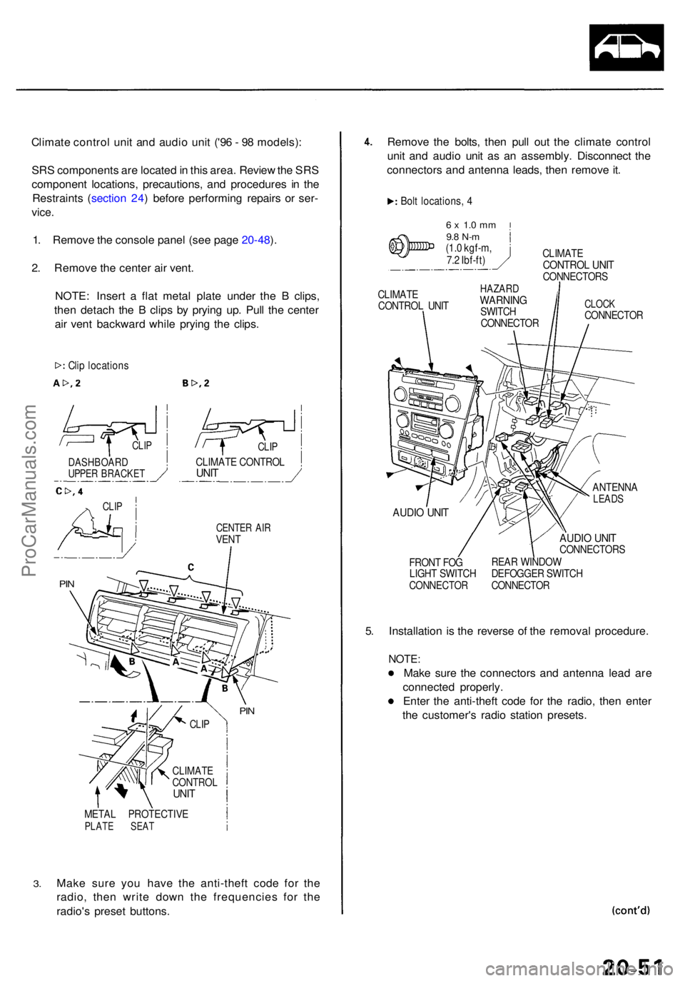
Climate contro l uni t an d audi o uni t ('9 6 - 9 8 models) :
SR S component s ar e locate d in thi s area . Revie w th e SR S
componen t locations , precautions , an d procedure s i n th e
Restraint s ( sectio n 24 ) befor e performin g repair s o r ser -
vice .
1. Remov e th e consol e pane l (se e pag e 20-48 ).
2 . Remov e th e cente r ai r vent .
NOTE : Inser t a fla t meta l plat e unde r th e B clips ,
the n detac h th e B clip s b y pryin g up . Pul l th e cente r
ai r ven t backwar d whil e pryin g th e clips .
CENTE R AI RVEN T
3.
META L PROTECTIV EPLATE SEA T
Make sur e yo u hav e th e anti-thef t cod e fo r th e
radio , the n writ e dow n th e frequencie s fo r th e
radio' s prese t buttons. Remov
e th e bolts , the n pul l ou t th e climat e contro l
uni t an d audi o uni t a s a n assembly . Disconnec t th e
connector s an d antenn a leads , the n remov e it .
Bol t locations , 4
6 x 1. 0 m m9.8 N- m(1.0 kgf-m ,
7. 2 Ibf-ft ) CLIMAT
E
CONTRO L UNI TCONNECTOR S
CLIMAT E
CONTRO L UNI THAZAR DWARNIN GSWITCH
CONNECTO RCLOCKCONNECTO R
AUDIO UNI T
FRON T FO G
LIGH T SWITC H
CONNECTO R
ANTENNALEADS
AUDIO UNI TCONNECTOR S
REA R WINDO W
DEFOGGE R SWITC H
CONNECTO R
5. Installatio n i s th e revers e o f th e remova l procedure .
NOTE:
Make sur e th e connector s an d antenn a lea d ar e
connecte d properly .
Ente r th e anti-thef t cod e fo r th e radio , the n ente r
th e customer' s radi o statio n presets .
Clip location s
CLIPCLIP
CLIMAT E CONTRO LUNITDASHBOAR DUPPER BRACKE T
CLIP
PIN
PIN
CLI P
CLIMAT ECONTRO LUNIT
ProCarManuals.com
Page 1367 of 1954

Dashboard
Componen t Removal/Installatio n (cont'd )
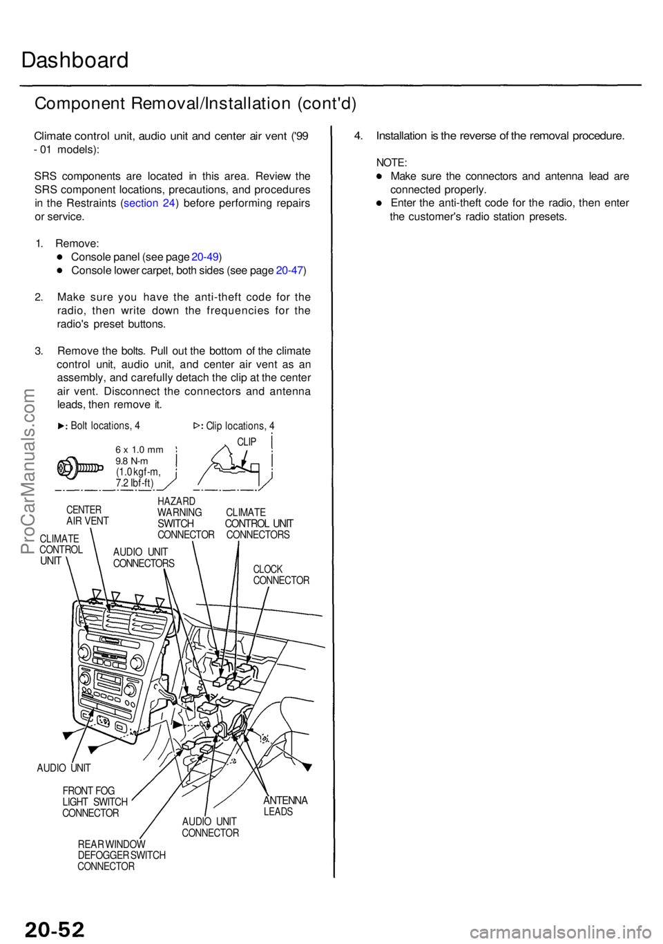
Climate contro l unit , audi o uni t an d cente r ai r ven t ('9 9
- 0 1 models) :
SR S component s ar e locate d i n thi s area . Revie w th e
SR S componen t locations , precautions , an d procedure s
i n th e Restraint s ( sectio n 24 ) befor e performin g repair s
o r service .
1 . Remove :
Consol e pane l (se e pag e 20-49 )
Consol e lowe r carpet , bot h side s (se e pag e 20-47 )
2.
3.
Mak e sur e yo u hav e th e anti-thef t cod e fo r th e
radio , the n writ e dow n th e frequencie s fo r th e
radio' s prese t buttons .
Remov e th e bolts . Pul l ou t th e botto m o f th e climat e
contro l unit , audi o unit , an d cente r ai r ven t a s a n
assembly , an d carefull y detac h th e cli p a t th e cente r
ai r vent . Disconnec t th e connector s an d antenn a
leads , the n remov e it .
Bol t locations , 4
6 x 1. 0 m m9.8 N- m(1.0 kgf-m ,
7. 2 Ibf-ft ) Cli
p locations , 4
CLI P
CENTE RAIR VEN T
CLIMAT ECONTRO LUNIT
HAZAR DWARNIN G CLIMAT ESWITCH CONTRO L UNI TCONNECTO R CONNECTOR S
CLOCKCONNECTO R
AUDIO UNI T
FRON T FO G
LIGH T SWITC H
CONNECTO R
REA R WINDO W
DEFOGGE R SWITC H
CONNECTO R
ANTENNALEADSAUDIO UNI TCONNECTO R
4. Installatio n is th e revers e o f th e remova l procedure .
NOTE:
Make sur e th e connector s an d antenn a lea d ar e
connecte d properly .
Ente r th e anti-thef t cod e fo r th e radio , the n ente r
th e customer' s radi o statio n presets .
AUDIO UNI T
CONNECTOR S
ProCarManuals.com
Page 1470 of 1954

Climate Contro l Uni t
Replacemen t Bul b Replacemen t
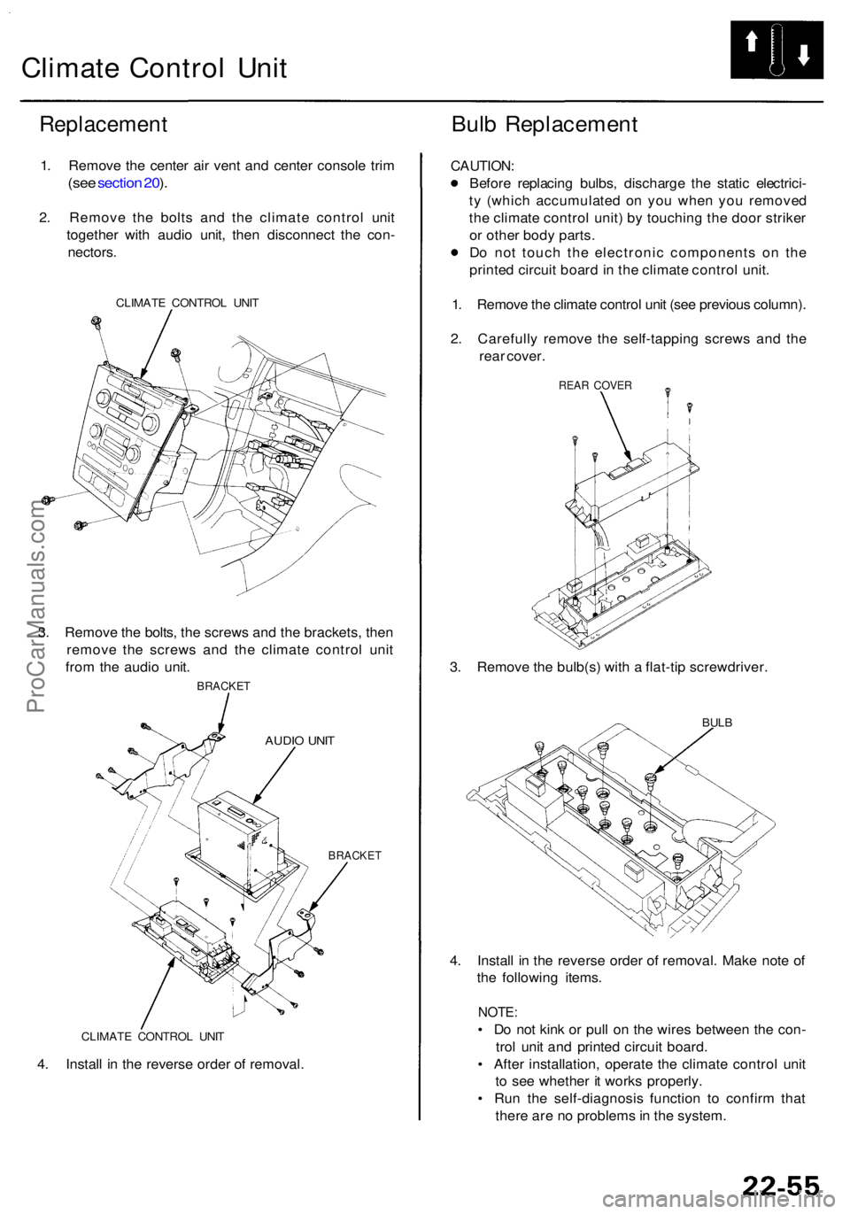
1. Remov e th e cente r ai r ven t an d cente r consol e tri m
(se e sectio n 20 ).
2 . Remov e th e bolt s an d th e climat e contro l uni t
togethe r wit h audi o unit , the n disconnec t th e con -
nectors .
CLIMAT E CONTRO L UNI T
3. Remov e th e bolts , th e screw s an d th e brackets , the n
remov e th e screw s an d th e climat e contro l uni t
fro m th e audi o unit .
BRACKE T
AUDIO UNI T
BRACKE T
CAUTION :
Before replacin g bulbs , discharg e th e stati c electrici -
t y (whic h accumulate d o n yo u whe n yo u remove d
th e climat e contro l unit ) b y touchin g th e doo r strike r
o r othe r bod y parts .
D o no t touc h th e electroni c component s o n th e
printe d circui t boar d in th e climat e contro l unit .
1 . Remov e th e climat e contro l uni t (se e previou s column) .
2 . Carefull y remov e th e self-tappin g screw s an d th e
rea r cover .
REAR COVE R
3. Remov e th e bulb(s ) wit h a flat-ti p screwdriver .
BULB
4. Instal l i n th e revers e orde r o f removal . Mak e not e o f
th e followin g items .
NOTE:
• D o no t kin k o r pul l o n th e wire s betwee n th e con -
tro l uni t an d printe d circui t board .
• Afte r installation , operat e th e climat e contro l uni t
t o se e whethe r i t work s properly .
• Ru n th e self-diagnosi s functio n t o confir m tha t
ther e ar e n o problem s in th e system .CLIMAT E CONTRO L UNI T
4. Instal l i n th e revers e orde r o f removal .
ProCarManuals.com
Page 1565 of 1954
Stereo Soun d Syste m
Audio Uni t Terminal s
'96 - 9 8 model s - Standar d Soun d System :
'9 9 - 0 1 model s - Bos e Soun d Syste m (withou t navigatio n system) :
'9 6 - 9 8 model s - Bos e Soun d System :
'9 9 - 0 1 model s - Bos e Soun d Syste m (wit h navigatio n system) :
ProCarManuals.com
Page 1567 of 1954

Stereo Soun d Syste m
Audio Uni t Remova l
SRS component s ar e locate d i n thi s area . Revie w th e
SR S componen t locations , precautions , an d procedure s
i n th e SR S ( sectio n 24 ) befor e performin g repair s o r
service .
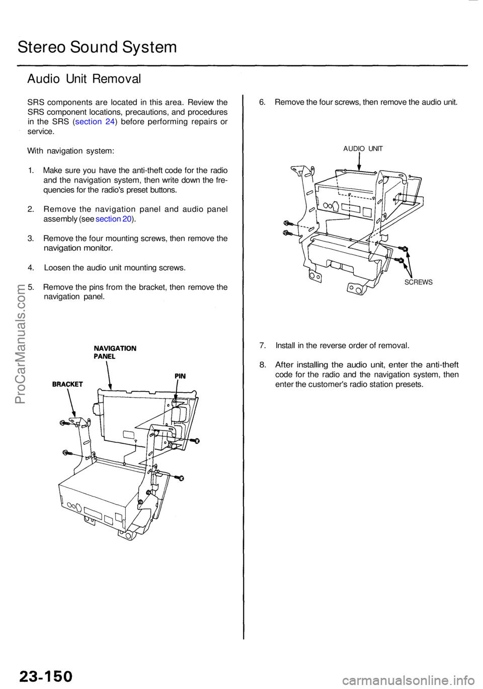
With navigatio n system :
1 . Mak e sur e yo u hav e th e anti-thef t cod e fo r th e radi o
an d th e navigatio n system , the n writ e dow n th e fre -
quencie s fo r th e radio' s prese t buttons .
2 . Remov e th e navigatio n pane l an d audi o pane l
assembl y (se e sectio n 20 ).
3 . Remov e th e fou r mountin g screws , the n remov e th e
navigatio n monitor .
4. Loose n th e audi o uni t mountin g screws .
5 . Remov e th e pin s fro m th e bracket , the n remov e th e
navigatio n panel .
7. Instal l i n th e revers e orde r o f removal .
8. Afte r installin g th e audi o unit , ente r th e anti-thef t
code fo r th e radi o an d th e navigatio n system , the n
ente r th e customer' s radi o statio n presets .
6
. Remov e th e fou r screws , the n remov e th e audi o unit .
AUDI O UNI T
SCREW S
ProCarManuals.com
Page 1568 of 1954
3. Remov e th e seve n (o r eight ) mountin g screws , the n
remov e th e audi o unit .
4. Instal l i n th e revers e orde r o f removal .
5 . Afte r installin g th e audi o unit , ente r th e anti-thef t
cod e fo r th e radio , the n ente r th e customer' s radi o
statio n presets .
Withou
t navigatio n system :
1 . Mak e sur e yo u hav e th e anti-thef t cod e fo r th e
radio , the n writ e dow n th e frequencie s fo r th e
radio' s prese t buttons .
2 . Remov e th e automati c climat e contro l pane l an d
audi o pane l assembl y (se e sectio n 20 ).
SCRE W
AUDIOUNIT
BRACKE T
BOLT
ProCarManuals.com
Page 1571 of 1954
Stereo Soun d Syste m
Radio Remot e Switc h Tes t
SRS component s ar e locate d i n thi s area . Revie w th e
SR S componen t locations , precautions , an d procedure s
i n th e SR S (sectio n 24 ) befor e performin g repair s o r
service .
1. Remov e th e switc h cove r fro m th e radi o remot e
switch.
RADIO REMOT E SWITC H
SWITC H COVE R
2P CONNECTO R
2. Remov e th e radi o remot e switc h fro m th e steerin g
whee l b y removin g th e tw o screws , an d disconnec t
th e 2 P connector . 3
. Remov e th e remot e switc h fro m th e steerin g whee l
(se e sectio n 17 ).
4 . Measur e resistanc e betwee n th e No . 1 an d No . 2
terminal s i n eac h switc h positio n accordin g t o th e
table .
Positio nResistanc e
Approx. 10 0
Approx . 35 0
Approx
. 77 0
Approx
. 3. 6
OF F
AUDIO/C H
(SEEK)
(VOL. UP)
(VOL . DOWN )
ProCarManuals.com