Page 1020 of 1954
5. Reconnect the feed line to upper side of the valve
body unit.
2. Position the line mounting cushions by aligning the
marks on the 10 mm return line (large diameter
line).
3. Install the feed line on the slot of the cushions.
4. Install the two line clamps on the line mounting
cushions as shown below.
Installation
CAUTION: Be careful not to bend or damage cylinder
lines A and B or the four fluid lines when installing the
gearbox.
1. Assemble the mounting bracket over the mount
cushion, then loosely install the gearbox on the rear
beam with two gearbox mounting bolts.
NOTE: Move the feed line over the gearbox so that
it does not interfere with the gearbox during instal-
lation.ProCarManuals.com
Page 1043 of 1954

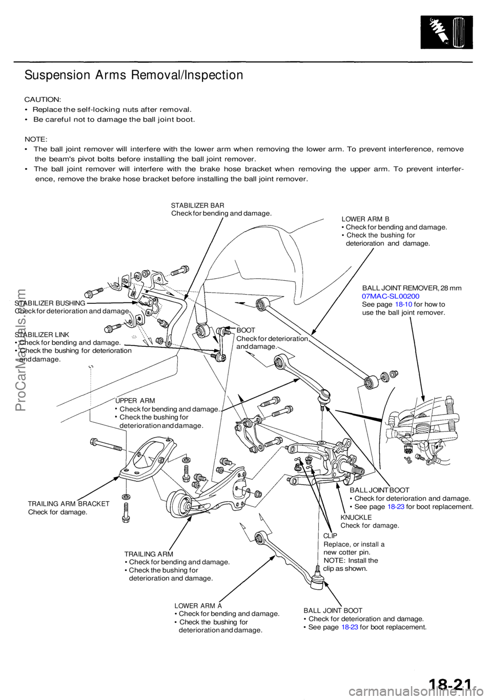
Suspension Arm s Removal/Inspectio n
CAUTION:
• Replac e th e self-lockin g nut s afte r removal .
• B e carefu l no t t o damag e th e bal l join t boot .
NOTE :
• Th e bal l join t remove r wil l interfer e wit h th e lowe r ar m whe n removin g th e lowe r arm . T o preven t interference , remov e
th e beam' s pivo t bolt s befor e installin g th e bal l join t remover .
• Th e bal l join t remove r wil l interfer e wit h th e brak e hos e bracke t whe n removin g th e uppe r arm . T o preven t interfer -
ence , remov e th e brak e hos e bracke t befor e installin g th e bal l join t remover .
STABILIZE R BA RChec k fo r bendin g an d damage .
STABILIZE R BUSHIN GCheck fo r deterioratio n an d damag e
STABILIZE R LIN K• Chec k fo r bendin g an d damage .• Chec k th e bushin g fo r deterioratio nand damage .
LOWER AR M B• Chec k fo r bendin g an d damage .• Chec k th e bushin g fo rdeterioratio n an d damage .
BAL L JOIN T REMOVER , 2 8 m m
07MAC-SL0020 0See pag e 18-1 0 fo r ho w to
us e th e bal l join t remover .
TRAILING AR M BRACKE TCheck fo r damage .
TRAILING AR M• Chec k fo r bendin g an d damage .
• Chec k th e bushin g fo r
deterioratio n an d damage .
LOWER AR M A• Chec k fo r bendin g an d damage .
• Chec k th e bushin g fo r
deterioratio n an d damage . BAL
L JOIN T BOO T
• Chec k fo r deterioratio n an d damage .
• Se e pag e 18-2 3 fo r boo t replacement .
KNUCKLECheck fo r damage .
CLIPReplace , o r instal l ane w cotte r pin .
NOTE : Instal l th e
clip a s shown .
BALL JOIN T BOO T• Chec k fo r deterioratio n an d damage .
• Se e pag e 18-2 3 fo r boo t replacement .
BOOTChec k fo r deterioration ,
an d damage .
UPPER AR MChec k fo r bendin g an d damage. .
Chec k th e bushin g fo r
deterioratio n an d damage .
ProCarManuals.com
Page 1485 of 1954

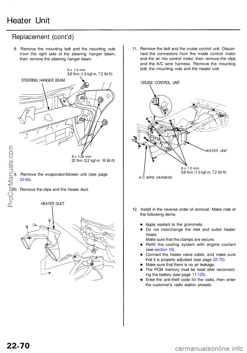
Heater Uni t
Replacemen t (cont'd )
8. Remov e th e mountin g bol t an d th e mountin g nut s
fro m th e righ t sid e o f th e steerin g hange r beam ,
the n remov e th e steerin g hange r beam .
6 x 1. 0 m m9.8 N- m (1. 0 kgf-m , 7. 2 Ibf-ft )
STEERIN G HANGE R BEA M
8 x 1.2 5 mm22 N- m (2. 2 kgf-m , 1 6 Ibf-ft )
9. Remov e th e evaporator/blowe r uni t (se e pag e
22-65 ).
10. Remov e th e clip s an d th e heate r duct .
HEATE R DUC T
11. Remov e th e bol t an d th e cruis e contro l unit . Discon -
nec t th e connector s fro m th e mod e contro l moto r
an d th e ai r mi x contro l motor , the n remov e th e clip s
an d th e A/ C wir e harness . Remov e th e mountin g
bolt , th e mountin g nut s an d th e heate r unit .
CRUIS E CONTRO L UNI T
HEATE R UNI T
6 x 1. 0 m m9.8 N- m (1. 0 kgf-m , 7. 2 Ibf-ft )
A/C WIR E HARNES S
12. Instal l i n th e revers e orde r o f removal . Mak e not e o f
the followin g items .
Apply sealan t t o th e grommets .
D o no t interchang e th e inle t an d outle t heate r
hoses.
Make sur e tha t th e clamp s ar e secure .
Refil l th e coolin g syste m wit h engin e coolan t
(se e sectio n 10 ).
Connec t th e heate r valv e cable , an d mak e sur e
tha t i t i s properl y adjuste d (se e pag e 22-72 ).
Mak e sur e tha t ther e is n o ai r leakage .
Th e PC M memor y mus t b e rese t afte r reconnect -
in g th e batter y (se e pag e 11-125 ).
Ente r th e anti-thef t cod e fo r th e radio , the n ente r
th e customer' s radi o statio n presets .
ProCarManuals.com
Page 1546 of 1954

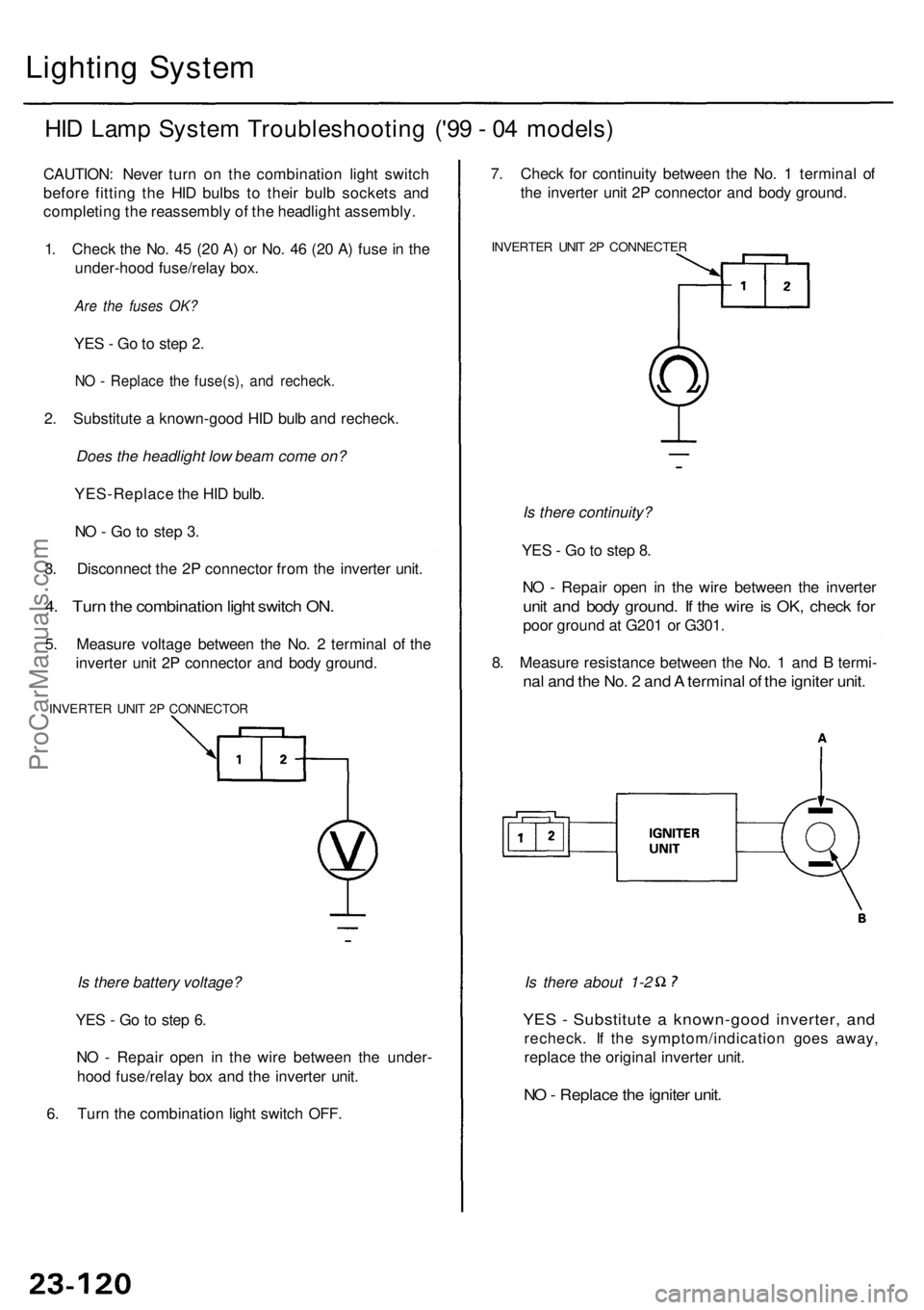
Lighting Syste m
HID Lam p Syste m Troubleshootin g ('9 9 - 0 4 models )
CAUTION : Neve r tur n o n th e combinatio n ligh t switc h
befor e fittin g th e HI D bulb s t o thei r bul b socket s an d
completin g th e reassembl y o f th e headligh t assembly .
1 . Chec k th e No . 4 5 (2 0 A ) o r No . 4 6 (2 0 A ) fus e in th e
under-hoo d fuse/rela y box .
Are the fuses OK?
YES - G o to ste p 2 .
NO - Replac e th e fuse(s) , an d recheck .
2. Substitut e a known-goo d HI D bul b an d recheck .
Does the headlight low beam come on?
YES-Replac e th e HI D bulb .
N O - G o t o ste p 3 .
3 . Disconnec t th e 2 P connecto r fro m th e inverte r unit .
4. Tur n th e combinatio n ligh t switc h ON .
5. Measur e voltag e betwee n th e No . 2 termina l o f th e
inverte r uni t 2 P connecto r an d bod y ground .
INVERTE R UNI T 2 P CONNECTO R
Is there battery voltage?
YE S - G o to ste p 6 .
N O - Repai r ope n i n th e wir e betwee n th e under -
hoo d fuse/rela y bo x an d th e inverte r unit .
6 . Tur n th e combinatio n ligh t switc h OFF .
YES - Substitut e a known-goo d inverter , an d
recheck . I f th e symptom/indicatio n goe s away ,
replac e th e origina l inverte r unit .
NO - Replac e th e ignite r unit .
Is there about 1-2
7
. Chec k fo r continuit y betwee n th e No . 1 termina l o f
th e inverte r uni t 2 P connecto r an d bod y ground .
INVERTE R UNI T 2 P CONNECTE R
Is there continuity?
YE S - G o to ste p 8 .
N O - Repai r ope n i n th e wir e betwee n th e inverte r
unit an d bod y ground . I f th e wir e is OK , chec k fo r
poo r groun d a t G20 1 o r G301 .
8 . Measur e resistanc e betwee n th e No . 1 an d B termi -
nal an d th e No . 2 an d A termina l o f th e ignite r unit .
ProCarManuals.com
Page 1547 of 1954

Headlights
Combinatio n Ligh t Switc h
Replacemen t
1. Remov e th e dashboar d lowe r cove r (se e sectio n 20 ).
2 . Remove the steering column covers (see
section 17 ).
3 . Disconnec t th e 14 P connecto r fro m th e combinatio n
ligh t switch , the n remov e th e tw o screw s an d th e
switch .
4 . Instal l th e combinatio n ligh t switc h i n th e revers e
orde r o f removal .
COMBINATIO N LIGH T SWITC H
14
P CONNECTO R
Replacemen t
CAUTION: Headlight s becom e ver y ho t i n use ; d o no t
touc h the m o r th e attachin g hardwar e immediatel y
afte r the y hav e bee n turne d off .
1 . Remov e th e fron t bumpe r an d fron t bumpe r uppe r
bea m (se e sectio n 20 ).
2 . Disconnec t th e connectors .
3 . Remov e th e fou r mountin g bolts , the n remov e th e
headligh t assembly .
HEADLIGH T
ASSEMBL Y
'9 6 - 9 8 models :
HEADLIGHT : 60/5 5 W
FRON T TUR N SIGNA L LIGHT : 2 1 W
FRON T PARKIN G LIGHT : 5 W x 2
FRON T FO G LIGHT : 5 5 W
SID E MARKE R LIGHT : 5 W
'9 9 - 0 1 models :
HEADLIGH T LO W BEAM : 3 5 W
HEADLIGH T HIG H BEAM : 5 5 W
FRON T TUR N SIGNAL/PARKIN G LIGHT : 27/ 8 W
SID E MARKE R LIGHT : 5 W
4. Instal l th e headligh t i n th e revers e orde r o f removal .
5 . Afte r replacement , adjus t th e headlight s t o loca l
requirements .
ProCarManuals.com