1996 ACURA RL KA9 fog light
[x] Cancel search: fog lightPage 1552 of 1954
Fog Light s
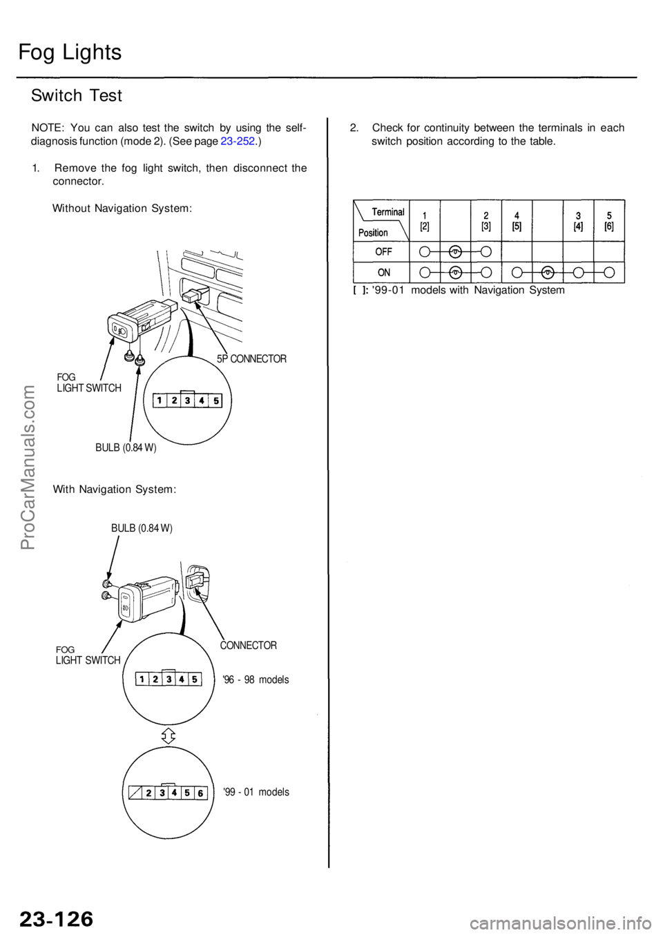
Switch Tes t
NOTE : Yo u ca n als o tes t th e switc h b y usin g th e self -
diagnosi s functio n (mod e 2) . (Se e pag e 23-252 .)
1 . Remov e th e fo g ligh t switch , the n disconnec t th e
connector .
Withou t Navigatio n System :
FOGLIGH T SWITC H
BUL B (0.8 4 W ) 5
P CONNECTO R
With Navigatio n System : 2
. Chec k fo r continuit y betwee n th e terminal s i n eac h
switc h positio n accordin g t o th e table .
'99-0 1 model s wit h Navigatio n Syste m
BULB (0.8 4 W )
FO GLIGH T SWITC H
CONNECTO R
'96 - 9 8 model s
'9 9 - 0 1 model s
ProCarManuals.com
Page 1553 of 1954
Adjustment
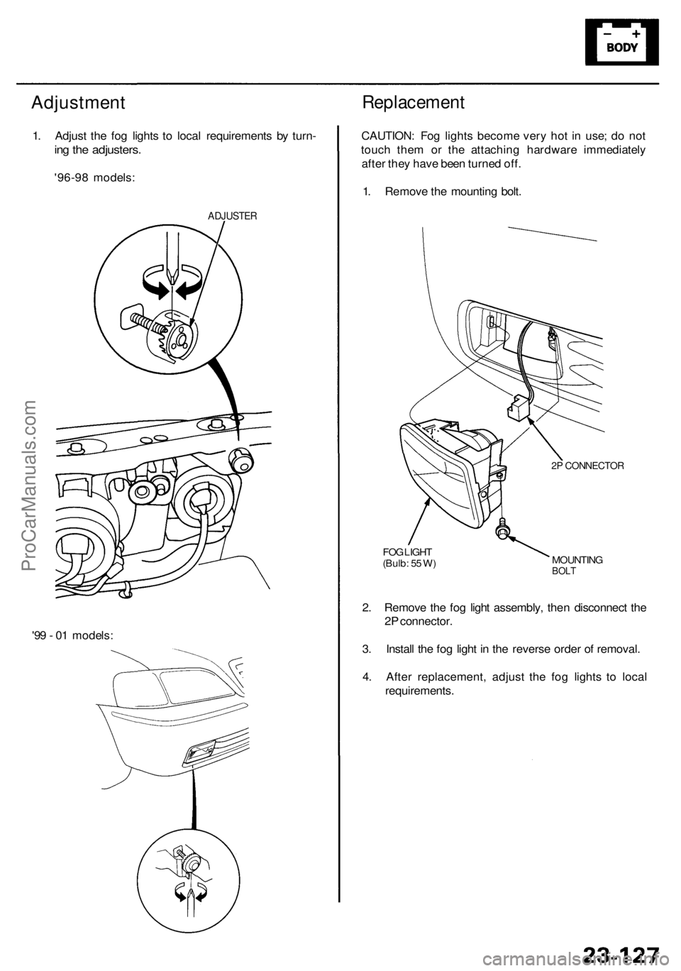
1. Adjus t th e fo g light s t o loca l requirement s b y turn -
ing th e adjusters .
'96-98 models :
ADJUSTE R
Replacemen t
CAUTION: Fo g light s becom e ver y ho t i n use ; d o no t
touc h the m o r th e attachin g hardwar e immediatel y
afte r the y hav e bee n turne d off .
1 . Remov e th e mountin g bolt .
2P CONNECTO R
MOUNTINGBOLT
FOG LIGH T
(Bulb : 5 5 W )
2. Remov e th e fo g ligh t assembly , the n disconnec t th e
2 P connector .
3 . Instal l th e fo g ligh t i n th e revers e orde r o f removal .
4 . Afte r replacement , adjus t th e fo g light s t o loca l
requirements .
'9
9 - 0 1 models :
ProCarManuals.com
Page 1645 of 1954
System Function s
• Multiple x Contro l Syste m (Multiple x function , Wak e up/slee p function , Fail-saf e function , Self-diagnosi s function* )
* : Self-diagnosi s functio n mod e 1 is th e self-diagnosi s fo r th e multiple x contro l system .
Self-diagnosi s functio n mod e 2 is th e failur e diagnosi s fo r th e inpu t lin e o f eac h system .
• Integrate d Contro l Syste m (Engin e oi l pressur e indicato r flashe r circuit , Key-i n reminde r circuit , Light-o n reminde r circuit ,
Sea t bel t reminde r circuit )
• Das h Light s Brightnes s Contro l
• Entr y Ligh t Contro l Syste m
• Rea r Windo w Defogge r
• Trun k li d Opene r
• Powe r Doo r Lock s (wit h keyles s entr y system )
• Powe r Windo w (wit h key-of f timer operation )
• Wiper/washer s (wit h spee d responden t intermitten t wiper )
• Securit y Alar m Syste m
• Interloc k Syste m (se e sectio n 14 )
Multiple x Communicatio n Syste m
Multiple x Communicatio n Function s
• T o reduc e th e numbe r o f wir e harnesses , digita l signal s ar e sen t vi a share d multiple x communicatio n line s rather than
sendin g norma l electrica l signal s throug h individua l wires .
• Th e inpu t signal s fro m eac h switc h ar e converte d t o digita l signal s a t th e centra l processin g uni t (CPU) . Th e digita l
signal s ar e sen t fro m th e transmitte r uni t t o th e receive r uni t a s seria l signals .
• Th e transmitte d signa l i s converte d t o a switc h signa l a t th e receive r unit , an d it operate s th e relate d component .
• Ther e ar e exclusiv e communicatio n line s betwee n eac h o f th e multiple x contro l units :
Door Driver' s (fro m th e doo r t o th e driver' s multiple x contro l units ) Wir e color : BRN/YE L
Driver's Passenger' s (fro m th e driver' s t o th e passenger' s multiple x contro l units ) Wir e color : BRN/WH T
Passenger' s Driver' s (fro m th e passenger' s t o th e driver' s multiple x contro l units ) Wir e color : RED/YE L
• Th e contro l unit s alway s communicat e vi a thes e line s whe n th e syste m is operating , an d the y sto p communicatin g
whe n th e syste m is OFF .
Wake-u p an d Slee p Function s
• Th e multiple x contro l syste m ha s "wake-up " an d "sleep " function s t o decreas e parasiti c dra w o n th e batter y whe n th e
ignitio n switc h is OFF .
• I n th e slee p mode , th e multiple x contro l uni t stop s th e function s (communicatio n an d CP U control ) whe n i t i s no t nec -
essar y fo r th e syste m to operate .
• A s soo n a s an y operatio n i s don e (fo r example , a doo r i s unlocked) , th e relate d contro l uni t i n th e slee p mod e wake s u p
an d begin s t o functio n a t once . Thi s contro l uni t als o send s a wake-u p signa l t o th e othe r contro l unit s vi a th e commu -
nicatio n lines .
• Whe n th e ignitio n switc h i s turne d OFF , ther e i s abou t a 30 secon d dela y befor e th e contro l unit s g o fro m th e wake-u p
mod e t o th e slee p mode .
• I f an y doo r i s open , th e slee p mod e wil l no t function .
Fail-safe Function s
• T o preven t imprope r operation , th e multiple x contro l syste m ha s a fail-saf e function . I n th e fail-saf e mode , th e outpu t
signa l i s fixe d whe n an y par t o f th e syste m malfunction s (fo r example , a fault y contro l uni t o r communicatio n line) .
• Eac h contro l uni t ha s a hardwar e fail-saf e functio n tha t fixe s th e outpu t signa l whe n ther e i s an y CP U malfunctio n an d
a softwar e fail-saf e functio n tha t ignore s th e signa l fro m th e malfunctionin g contro l uni t an d allow s th e syste m to
operat e normally .
ProCarManuals.com
Page 1656 of 1954
Multiplex Contro l Syste m
Self-diagnosi s Functio n (Mod e 2 )
Fro m mod e 1 , disconnec t th e SC S servic e connecto r fro m th e multiple x contro l inspectio n connecto r fo r 5 to 1 0
seconds , the n reconnec t th e SC S servic e connecto r again , an d th e functio n goe s fro m mod e 1 to mod e 2 .
T o cance l mod e 2 , disconnec t th e SC S servic e connecto r fro m th e multiple x contro l inspectio n connecto r fo r mor e tha n 1 0
second s o r tur n th e ignitio n switc h OFF .
1 . Operat e th e switche s a s show n belo w in mod e 2 .
2 . I f th e relate d circui t lin e o f th e switc h i s OK , th e functio n indicate s thi s b y th e ignitio n ke y ligh t blinkin g onc e an d th e
beepe r soundin g once .
NOTE : I f th e lin e is faulty , ther e shoul d b e n o indication . Refe r t o th e test s fo r eac h system .
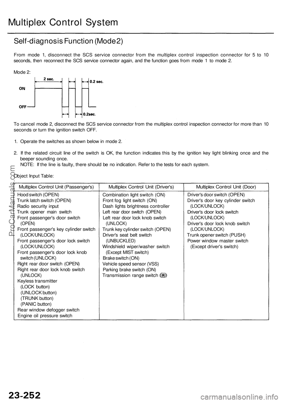
Objec t Inpu t Table :
Mod
e 2 :
Hoo d switc h (OPEN )
Trun k latc h switc h (OPEN )
Radi o securit y inpu t
Trun k opene r mai n switc h
Fron t passenger' s doo r switc h
(OPEN )
Front passenger' s ke y cylinde r switc h
(LOCK/UNLOCK )
Front passenger' s doo r loc k switc h
(LOCK/UNLOCK )
Front passenger' s doo r loc k kno b
switc h (UNLOCK )
Righ t rea r doo r switc h (OPEN )
Righ t rea r doo r loc k kno b switc h
(UNLOCK )
Keyless transmitte r
(LOC K button )
(UNLOC K button )
(TRUN K button )
(PANI C button )
Rea r windo w defogge r switc h
Engin e oi l pressur e switc h
Multiple x Contro l Uni t (Passenger's )Multiplex Contro l Uni t (Driver's )
Combinatio n ligh t switc h (ON )
Fron t fo g ligh t switc h (ON )
Das h light s brightnes s controlle r
Lef t rea r doo r switc h (OPEN )
Lef t rea r doo r loc k kno b switc h
(UNLOCK )
Trunk ke y cylinde r switc h (OPEN )
Driver' s sea t bel t switc h
(UNBUCKLED )
Windshield wiper/washe r switc h
(Excep t MIS T switch )
Brak e switc h (ON )
Vehicl e spee d senso r (VSS )
Parkin g brak e switc h (ON )
Transmissio n rang e switc h
Multiple x Contro l Uni t (Door )
Driver' s doo r switc h (OPEN )
Driver' s doo r ke y cylinde r switc h
(LOCK/UNLOCK )
Driver's doo r loc k switc h
(LOCK/UNLOCK )
Driver's doo r loc k kno b switc h
(LOCK/UNLOCK )
Trunk opene r switc h (PUSH )
Powe r windo w maste r switc h
(Excep t driver' s switch )
ProCarManuals.com
Page 1667 of 1954
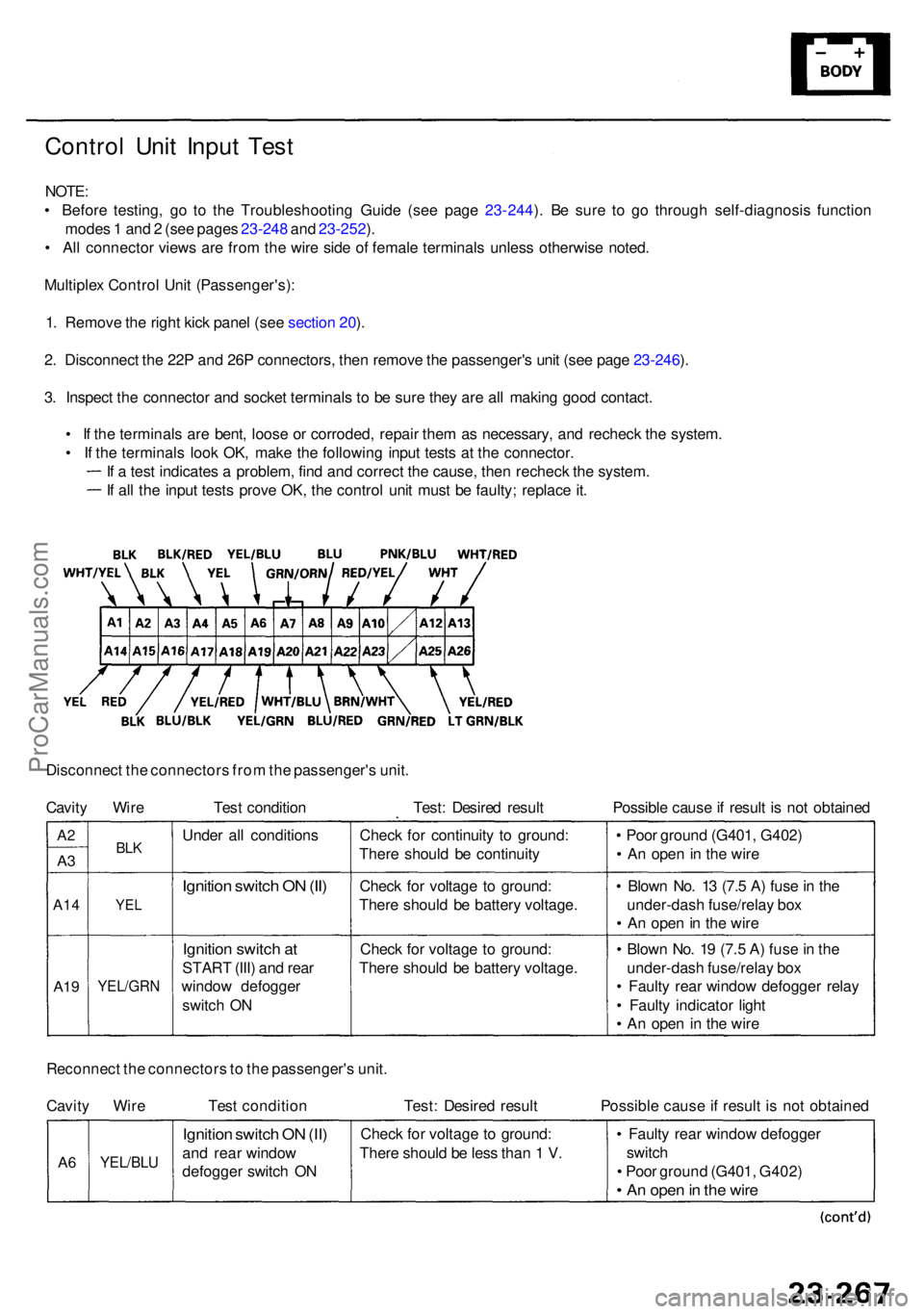
Control Uni t Inpu t Tes t
NOTE :
• Befor e testing , g o t o th e Troubleshootin g Guid e (se e pag e 23-244 ). B e sur e t o g o throug h self-diagnosi s functio n
mode s 1 an d 2 (se e page s 23-24 8 an d 23-252 ).
• Al l connecto r view s ar e fro m th e wir e sid e o f femal e terminal s unles s otherwis e noted .
Multiple x Contro l Uni t (Passenger's) :
1 . Remov e th e righ t kic k pane l (se e sectio n 20 ).
2 . Disconnec t th e 22 P an d 26 P connectors , the n remov e th e passenger' s uni t (se e pag e 23-246 ).
3 . Inspec t th e connecto r an d socke t terminal s t o b e sur e the y ar e al l makin g goo d contact .
• I f th e terminal s ar e bent , loos e o r corroded , repai r the m a s necessary , an d rechec k th e system .
• I f th e terminal s loo k OK , mak e th e followin g inpu t test s a t th e connector .
I f a tes t indicate s a problem , fin d an d correc t th e cause , the n rechec k th e system .
I f al l th e inpu t test s prov e OK , th e contro l uni t mus t b e faulty ; replac e it .
Disconnec t th e connector s fro m th e passenger' s unit .
Cavit y Wir e Tes t conditio n Test : Desire d resul t Possibl e caus e if resul t i s no t obtaine d
Ignition switc h O N (II )
Ignitio n switc h a t
STAR T (III ) an d rea r
windo w defogge r
switc h O N
YEL/GR N
YEL
BLKUnde r al l condition sCheck fo r continuit y t o ground :
Ther e shoul d b e continuit y
Chec k fo r voltag e t o ground :
Ther e shoul d b e batter y voltage .
Chec k fo r voltag e t o ground :
Ther e shoul d b e batter y voltage .
A19
A1 4
A3
A 2
• Blow n No . 1 9 (7. 5 A ) fus e in th e
under-das h fuse/rela y bo x
• Fault y rea r windo w defogge r rela y
• Fault y indicator light
• A n ope n i n th e wir e
•
Blow n No . 1 3 (7. 5 A ) fus e in th e
under-das h fuse/rela y bo x
• A n ope n in th e wir e
•
Poo r groun d (G401 , G402 )
• A n ope n in th e wir e
Reconnec t th e connector s to th e passenger' s unit .
Cavit y Wir e Tes t conditio n Test : Desire d resul t Possibl e caus e if resul t i s no t obtaine d
• Fault y rea r windo w defogge r
switc h
• Poo r groun d (G401 , G402 )
• A n ope n in th e wir e
Chec k fo r voltag e t o ground :
Ther e shoul d b e les s tha n 1 V .Ignitio n switc h O N (II )
an d rea r windo w
defogge r switc h O NYEL/BL UA6
ProCarManuals.com
Page 1670 of 1954
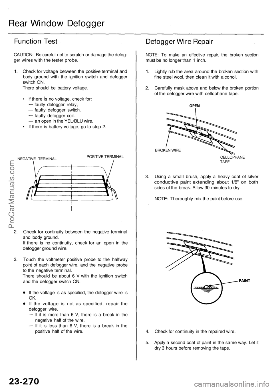
Rear Windo w Defogge r
Function Tes t
CAUTION : B e carefu l no t t o scratc h o r damag e th e defog -
ge r wire s wit h th e teste r probe .
1. Chec k fo r voltag e betwee n th e positiv e termina l an d
bod y groun d wit h th e ignitio n switc h an d defogge r
switc h ON .
Ther e shoul d b e batter y voltage .
• I f ther e is n o voltage , chec k for :
fault y defogge r relay ,
fault y defogge r switch .
fault y defogge r coil .
a n ope n in th e YEL/BL U wire .
• I f ther e i s batter y voltage , g o t o ste p 2 .
NEGATIV E TERMINA LPOSITIVE TERMINA L
2. Chec k fo r continuit y betwee n th e negativ e termina l
and bod y ground .
I f ther e i s n o continuity , chec k fo r a n ope n i n th e
defogge r groun d wire .
3. Touc h th e voltmete r positiv e prob e t o th e halfwa y
poin t o f eac h defogge r wire , an d th e negativ e prob e
t o th e negativ e terminal .
Ther e shoul d b e abou t 6 V with th e ignitio n switc h
an d th e defogge r switc h ON .
I f th e voltag e i s a s specified , th e defogge r wir e i s
OK .
If th e voltag e i s no t a s specified , repai r th e
defogge r wire .
I f i t i s mor e tha n 6 V , ther e i s a brea k i n th e
negativ e hal f o f th e wire .
I f i t i s les s tha n 6 V , ther e i s a brea k i n th e
positiv e hal f o f th e wire .
Defogge r Wir e Repai r
NOTE: T o mak e a n effectiv e repair , th e broke n sectio n
mus t b e n o longe r tha n 1 inch .
1. Lightl y ru b th e are a aroun d th e broke n sectio n wit h
fine stee l wool , the n clea n it wit h alcohol .
2 . Carefull y mas k abov e an d belo w th e broke n portio n
o f th e defogge r wir e wit h cellophan e tape .
3 . Usin g a smal l brush , appl y a heav y coa t o f silve r
conductiv e pain t extendin g abou t 1/8 " o n bot h
sides o f th e break . Allo w 3 0 minute s t o dry .
BROKE N WIR E
CELLOPHAN ETAPE
NOTE : Thoroughl y mi x th e pain t befor e use .
4. Chec k fo r continuit y in th e repaire d wire .
5 . Appl y a secon d coa t o f pain t i n th e sam e way . Le t i t
dr y 3 hour s befor e removin g th e tape .
ProCarManuals.com