1996 ACURA RL KA9 check engine light
[x] Cancel search: check engine lightPage 1196 of 1954

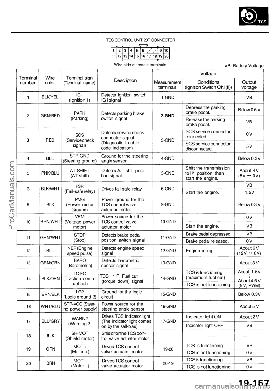
TCS CONTROL UNIT 20P CONNECTOR
Wire side of female terminals
VB: Battery Voltage
Terminal
number
1
2
4
5
6
9
10
11
12
13
14
15
16
17
20
Wire
color
BLK/YEL
GRN/RED
BLU
PNK/BLU
BLK/WHT
BLK
BRN/WHT
GRN/WHT
BLU
GRN/ORN
BLK/ORN
BRN/BLK
WHT/BLU
BLU/GRY
GRN
BRN
Terminal sign
(Terminal name)
IG1
(Ignition 1)
PARK
(Parking)
SCS
(Service check
signal)
STR-GND
(Steering ground)
AT-SHIFT
(AT shift)
FSR
(Fail-safe relay)
PMG
(Power motor
Ground)
VPM
(Voltage power
motor)
STOP
(Stop)
NEP (Engine
speed pulse)
BARO
(Barometric)
TC-FC
(Traction control
fuel cut)
LG2
(Logic ground 2)
STR-VCC (Steer-
ing power supply)
WARN2
(Warning 2)
SH-MOT
(Shield motor)
MOT +
(Motor +)
MOT-
(Motor -)
Description
Detects ignition switch
IG1 signal
Detects parking brake
switch signal
Detects service check
connector signal
(Diagnostic trouble
code indication)
Ground for the steering
angle sensor
Detects A/T shift posi-
tion signal
Drives fail-safe relay
Power ground for the
TCS control valve
actuator motor
Power source for the
TCS control valve
actuator motor
Detects brake pedal
position switch signal
Detects engine speed
signal
Detects barometric
sensor signal
TCS Fl, Fuel cut
(torque down) signal
Ground for the logic
circuit
Power source for the
steering angle sensor
Drives TCS indicator light
(The indicator light comes
on by the self-bias)
Shield for the TCS con-
trol valve actuator motor
Drives TCS control
valve actuator motor
Drives TCS control
valve actuator motor
Measurement
terminals
1-GND
2
3-GND
4-GND
5-GND
6-GND
9-GND
10-GND
11-GND
12-GND
13-GND
14-GND
15-GND
16-GND
17-GND
19-20
20-19
Voltage
Conditions
(Ignition Switch ON (II))
Depress the parking
brake pedal.
Release the parking
brake pedal.
SCS service connector
connected.
SCS service connector
disconnected.
Shift the transmission
to position, then
start the engine.
Start the engine.
Start the engine.
Brake pedal depressed.
Brake pedal released.
Engine idling
TCS is functioning,
(maximum fuel cut)
TCS is not functioning.
Indicator light ON
Indicator light OFF
TCS is functioning.
TCS is not functioning.
TCS is functioning.
TCS is not functioning.
Output
voltage
VB
Below 0.6 V
VB
0V
5V
Below 0.3V
About 4V
(5V 0V)
VB
1.5V
Below 0.3 V
0V
VB
VB
0V
About 6V
(12V
0V)
About 3 V
About 1.5V
About 4.5 V
(5 V,
PWM)
Below 0.3V
About 5 V
About 2 V
VB
VB
0V
VB
0VProCarManuals.com
Page 1212 of 1954

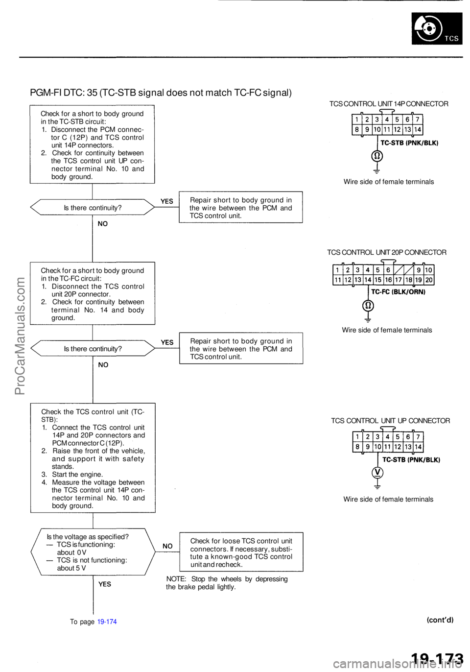
PGM-FI DTC : 3 5 (TC-ST B signa l doe s no t matc h TC-F C signal )
Check fo r a shor t t o bod y groun d
i n th e TC-ST B circuit :
1 . Disconnec t th e PC M connec -
to r C (12P ) an d TC S contro l
uni t 14 P connectors .
2 . Chec k fo r continuit y betwee n
th e TC S contro l uni t U P con -
necto r termina l No . 1 0 an d
bod y ground . TC
S CONTRO L UNI T 14 P CONNECTO R
Wir e sid e o f femal e terminal s
I s ther e continuity ? Repai
r shor t t o bod y groun d in
th e wir e betwee n th e PC M an d
TC S contro l unit .
TCS CONTRO L UNI T 20 P CONNECTO R
Chec k fo r a shor t t o bod y groun d
i n th e TC-F C circuit :
1 . Disconnec t th e TC S contro l
uni t 20 P connector .
2 . Chec k fo r continuit y betwee n
termina l No . 1 4 an d bod y
ground .
Is ther e continuity ?Repair shor t t o bod y groun d in
th e wir e betwee n th e PC M an d
TC S contro l unit . Wir
e sid e o f femal e terminal s
Chec k th e TC S contro l uni t (TC -
STB) :1. Connec t th e TC S contro l uni t
14 P an d 20 P connector s an d
PC M connecto r C (12P) .
2 . Rais e th e fron t o f th e vehicle ,
and suppor t i t wit h safet ystands.
3 . Star t th e engine .
4 . Measur e th e voltag e betwee n
th e TC S contro l uni t 14 P con -
necto r termina l No . 1 0 an d
bod y ground . TC
S CONTRO L UNI T U P CONNECTO R
Wir e sid e o f femal e terminal s
I s th e voltag e a s specified ?
TCS is functioning :about 0 V
TC S is no t functioning :
abou t 5 V Chec
k fo r loos e TC S contro l uni t
connectors . I f necessary , substi -
tut e a known-goo d TC S contro l
uni t an d recheck .
To pag e 19-17 4
NOTE : Sto p th e wheel s b y depressin g
th e brak e peda l lightly .
ProCarManuals.com
Page 1283 of 1954

Troubleshooting
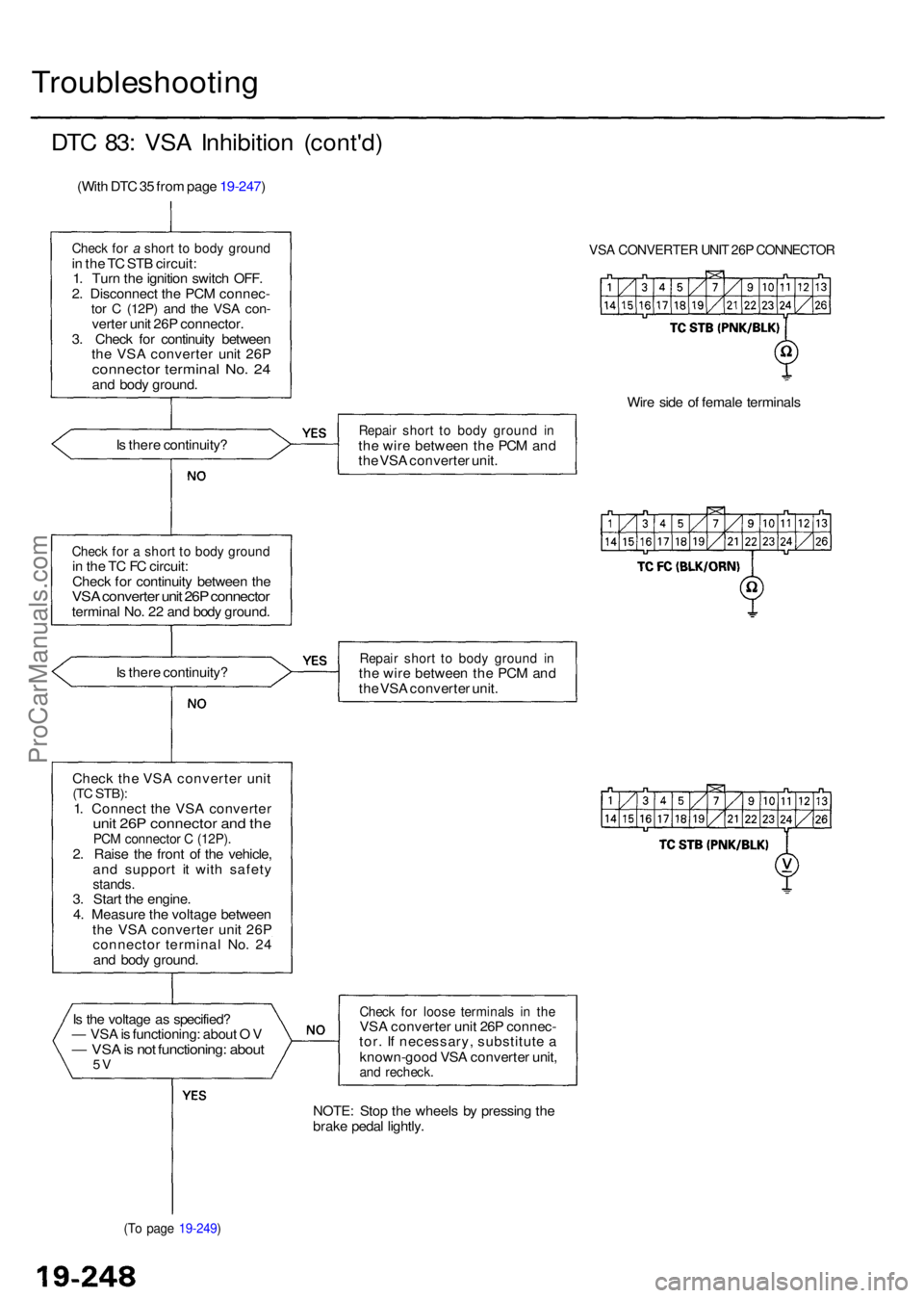
DTC 83 : VS A Inhibitio n (cont'd )
(With DT C 35 fro m pag e 19-247 )
Check fo r a shor t t o bod y groun din th e T C ST B circuit :
1 . Tur n th e ignitio n switc h OFF .
2 . Disconnec t th e PC M connec -
tor C (12P ) and th e VS A con -verte r uni t 26 P connector .
3 . Chec k fo r continuit y betwee n
th e VS A converte r uni t 26 P
connecto r termina l No . 2 4an d bod y ground .
I s ther e continuity ?
Check fo r a shor t t o bod y groun din th e T C F C circuit :
Chec k fo r continuit y betwee n th e
VS A converte r uni t 26 P connecto rterminal No . 2 2 an d bod y ground .
I s ther e continuity ?
Chec k the VSA converte r uni t
(TC STB) :1. Connec t th e VS A converte runit 26 P connecto r an d th ePC M connecto r C (12P) .2. Rais e th e fron t o f th e vehicle ,
an d suppor t i t wit h safet y
stands.3. Star t th e engine .
4 . Measur e th e voltag e betwee n
th e VS A converte r uni t 26 P
connecto r termina l No . 2 4
an d bod y ground .
I s th e voltag e a s specified ?
— VS A is functioning : abou t O V
— VS A is no t functioning : abou t5V
(T o pag e 19-249 )
VSA CONVERTE R UNI T 26 P CONNECTO R
Wire sid e o f femal e terminal s
Repair shor t t o bod y groun d i nth e wir e betwee n th e PC M an d
th e VS A converte r unit .
Repai r shor t t o bod y groun d i nth e wir e betwee n th e PC M an d
th e VS A converte r unit .
Chec k fo r loos e terminal s i n th eVS A converte r uni t 26 P connec -
tor . I f necessary , substitut e a
known-goo d VS A converte r unit ,
and recheck .
NOTE: Sto p th e wheel s b y pressin g th e
brak e peda l lightly .
ProCarManuals.com
Page 1595 of 1954

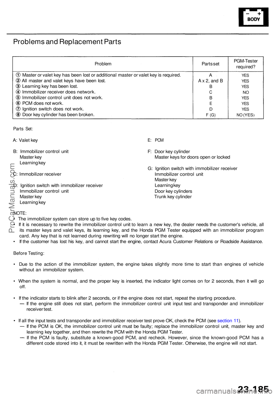
Problems an d Replacemen t Part s
Proble m
Master o r vale t ke y ha s bee n los t o r additiona l maste r o r vale t ke y is required .
Al l maste r an d vale t key s hav e bee n lost .
Learnin g ke y ha s bee n lost .
Immobilize r receive r doe s network .
Immobilize r contro l uni t doe s no t work .
PC M doe s no t work .
Ignitio n switc h doe s no t work .
Doo r ke y cylinde r ha s bee n broken . Part
s se t
PGM-Teste r
required?
YES
YES
YE S
NO
YE S
YE S
YES
NO (YES )
A
A x 2 , an d B
B
C
B
E
D
F (G )
Part s Set :
A: Vale t ke y
B : Immobilize r contro l uni t
Maste r ke y
Learnin g ke y
C : Immobilize r receive r
D : Ignitio n switc h wit h immobilize r receive r
Immobilize r contro l uni t
Maste r ke y
Learnin g ke yE: PC M
F: Doo r ke y cylinde r
Maste r key s fo r door s ope n o r locke d
G : Ignitio n switc h wit h immobilize r receive r
Immobilize r contro l uni t
Maste r ke y
Learnin g ke y
Doo r ke y cylinder s
Trun k ke y cylinde r
NOTE:
• Th e immobilize r syste m ca n stor e u p to fiv e ke y codes .
• I f i t i s necessar y t o rewrit e th e immobilize r contro l uni t t o lear n a ne w key , th e deale r need s th e customer' s vehicle , al l
it s maste r key s an d vale t keys , it s learnin g key , an d th e Hond a PG M Teste r equippe d wit h a n immobilize r progra m
card . An y ke y tha t i s no t learne d durin g rewritin g wil l n o longe r star t th e engine .
• I f th e custome r ha s los t hi s key , an d canno t star t th e engine , contac t Acur a Custome r Relation s o r Roadsid e Assistance .
Before Testing :
• Du e t o th e actio n o f th e immobilize r system , th e engin e take s slightl y mor e tim e t o star t tha n engine s o f vehicl e
withou t a n immobilize r system .
• Whe n th e syste m is normal , an d th e prope r ke y i s inserted , th e indicato r ligh t come s o n fo r 2 seconds , the n i t wil l g o
off .
• I f th e indicato r start s t o blin k afte r 2 seconds , o r i f th e engin e doe s no t start , repea t th e startin g procedure .
If th e engin e stil l doe s no t start , perfor m th e immobilize r contro l uni t inpu t tes t an d transponde r an d immobilize r
receive r test .
• I f al l th e inpu t test s an d transponde r an d immobilize r receive r tes t prov e OK , chec k th e PC M (se e sectio n 11 ).
I f th e PC M is OK , th e immobilize r contro l uni t mus t b e faulty ; replac e th e immobilize r contro l unit , maste r ke y an d
learnin g ke y together , an d the n rewrit e th e PC M wit h th e Hond a PG M Tester .
If th e PC M is faulty , substitut e a known-goo d PCM , an d recheck . However , sinc e th e known-goo d PC M ha s a
differen t cod e store d int o it , i t mus t b e rewritte n wit h th e Hond a PG M Tester . Otherwise , th e engin e wil l no t start .
ProCarManuals.com