Page 403 of 2543
4. WHEN REPLACING 3 SOLENOIDS
(a) Disconnect the connectors from the solenoids.
(b) Remove the solenoid mounting bolts.
Torque: 10 NVm (100 kgfVcm, 7 ftVlbf)
(c) Remove the solenoids.
5. REMOVE OIL STRAINER
REMOVAL NOTICE: Be careful as some fluid will come
out with the oil strainer.
Remove the 3 bolts, and the oil strainer and gasket.
Torque: 10 NVm (100 kgfVcm, 7 ftVlbf)
INSTALLATION HINT: If necessary, replace the strainer or
case gasket.
6. REMOVE OIL PIPES
Pry up both pipe ends with a large screwdriver and remove
the 2 pipes.
INSTALLATION NOTICE: Make sure that the oil pipes or
the magnets do not interfere with the oil pan.
± AT340E (2JZ±GE) AUTOMATIC TRANSMISSIONON±VEHICLE REPAIRAT1±17
Page 406 of 2543
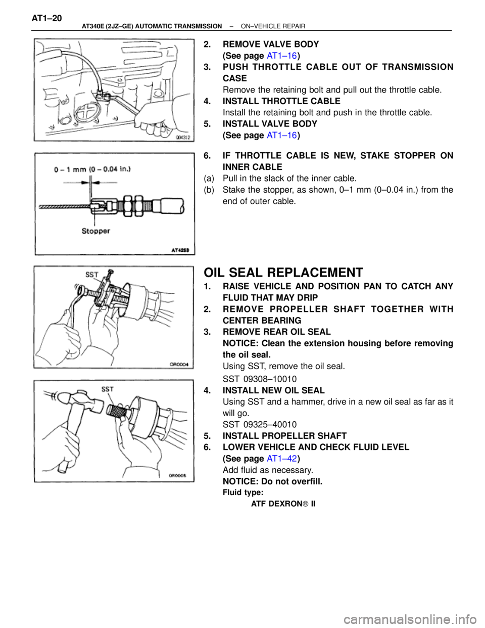
2. REMOVE VALVE BODY
(See page AT1±16)
3. PUSH THROTTLE CABLE OUT OF TRANSMISSION
CASE
Remove the retaining bolt and pull out the throttle cable.
4. INSTALL THROTTLE CABLE
Install the retaining bolt and push in the throttle cable.
5. INSTALL VALVE BODY
(See page AT1±16)
6. IF THROTTLE CABLE IS NEW, STAKE STOPPER ON
INNER CABLE
(a) Pull in the slack of the inner cable.
(b) Stake the stopper, as shown, 0±1 mm (0±0.04 in.) from the
end of outer cable.
OIL SEAL REPLACEMENT
1. RAISE VEHICLE AND POSITION PAN TO CATCH ANY
FLUID THAT MAY DRIP
2. REMOVE PROPELLER SHAFT TOGETHER WITH
CENTER BEARING
3. REMOVE REAR OIL SEAL
NOTICE: Clean the extension housing before removing
the oil seal.
Using SST, remove the oil seal.
SST 09308±10010
4. INSTALL NEW OIL SEAL
Using SST and a hammer, drive in a new oil seal as far as it
will go.
SST 09325±40010
5. INSTALL PROPELLER SHAFT
6. LOWER VEHICLE AND CHECK FLUID LEVEL
(See page AT1±42)
Add fluid as necessary.
NOTICE: Do not overfill.
Fluid type:
ATF DEXRON[ II
AT1±20± AT340E (2JZ±GE) AUTOMATIC TRANSMISSIONON±VEHICLE REPAIR
Page 407 of 2543
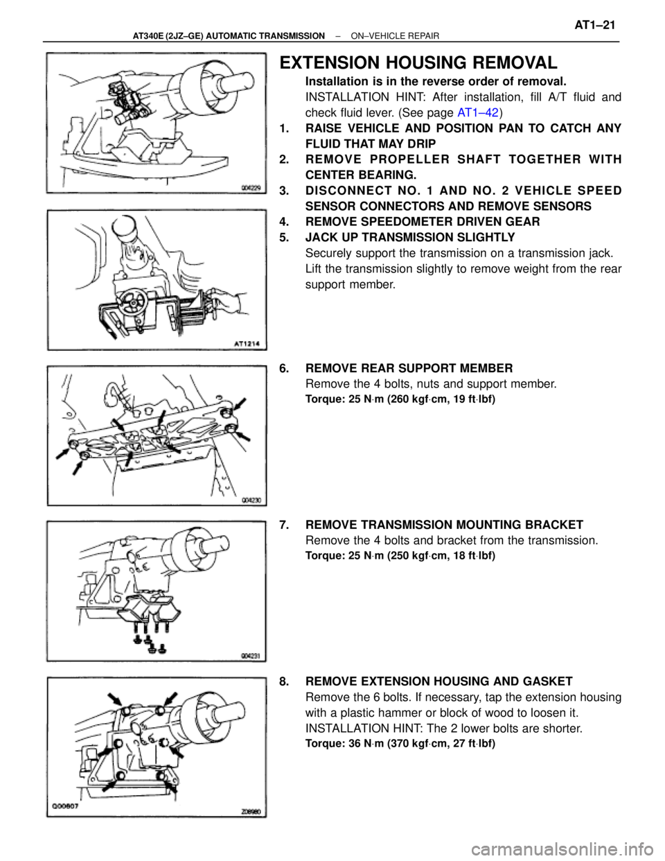
EXTENSION HOUSING REMOVAL
Installation is in the reverse order of removal.
INSTALLATION HINT: After installation, fill A/T fluid and
check fluid lever. (See page AT1±42)
1. RAISE VEHICLE AND POSITION PAN TO CATCH ANY
FLUID THAT MAY DRIP
2. REMOVE PROPELLER SHAFT TOGETHER WITH
CENTER BEARING.
3. DISCONNECT NO. 1 AND NO. 2 VEHICLE SPEED
SENSOR CONNECTORS AND REMOVE SENSORS
4. REMOVE SPEEDOMETER DRIVEN GEAR
5. JACK UP TRANSMISSION SLIGHTLY
Securely support the transmission on a transmission jack.
Lift the transmission slightly to remove weight from the rear
support member.
6. REMOVE REAR SUPPORT MEMBER
Remove the 4 bolts, nuts and support member.
Torque: 25 NVm (260 kgfVcm, 19 ftVlbf)
7. REMOVE TRANSMISSION MOUNTING BRACKET
Remove the 4 bolts and bracket from the transmission.
Torque: 25 NVm (250 kgfVcm, 18 ftVlbf)
8. REMOVE EXTENSION HOUSING AND GASKET
Remove the 6 bolts. If necessary, tap the extension housing
with a plastic hammer or block of wood to loosen it.
INSTALLATION HINT: The 2 lower bolts are shorter.
Torque: 36 NVm (370 kgfVcm, 27 ftVlbf)
± AT340E (2JZ±GE) AUTOMATIC TRANSMISSIONON±VEHICLE REPAIRAT1±21
Page 409 of 2543
TRANSMISSION REMOVAL
Installation is in the reverse order of removal.
INSTALLATION HINT: After installation, fill A/T fluid and
check fluid level. (See page AT1±42)
1. REMOVE A/T FLUID LEVEL GAUGE
2. REMOVE FILLER PIPE
Remove the bolt and pipe.
3. DISCONNECT THROTTLE CABLE
4. REMOVE EXHAUST PIPE
(See page EG±83)
5. REMOVE HEAT INSULATOR
Remove the 4 nuts and the heat insulator.
Torque: 5.4 NVm (55 kgfVcm, 48 in.Vlbf)
± AT340E (2JZ±GE) AUTOMATIC TRANSMISSIONASSEMBLY REMOVAL AND INSTALLATIONAT1±23
Page 410 of 2543
6. REMOVE REAR CENTER FLOOR CROSSMEMBER
BRACE
Normal Roof:
Remove the 4 bolts and center floor crossmember brace.
Torque: 13 NVm (130 kgfVcm, 9 ftVlbf)
Sport Roof:
Remove the 6 bolts and center floor crossmember brace.
Torque: 13 NVm (130 kgfVcm, 9 ftVlbf)
7. REMOVE PROPELLER SHAFT
(See page PR±7)
8. REMOVE SHIFT CONTROL ROD
(a) Remove the nut from shift lever.
INSTALLATION HINT: Inspect and adjust the park/ neutral
position switch.
(b) Remove the nut and control rod with the control shaft lever.
Torque: 16 NVm (160 kgfVcm, 12 ftVlbf)
9. DISCONNECT THESE CONNECTORS
w No.1 vehicle speed sensor connector
w No.2 vehicle speed sensor connector
w Solenoid wire connector
w Sensor cover
w A/T fluid temp. sensor connector
w Park/neutral position switch connector
10. DISCONNECT 3 WIRE CLAMPS FROM THE BRACKET
ON TRANSMISSION AT1±24
± AT340E (2JZ±GE) AUTOMATIC TRANSMISSIONASSEMBLY REMOVAL AND INSTALLATION
Page 423 of 2543
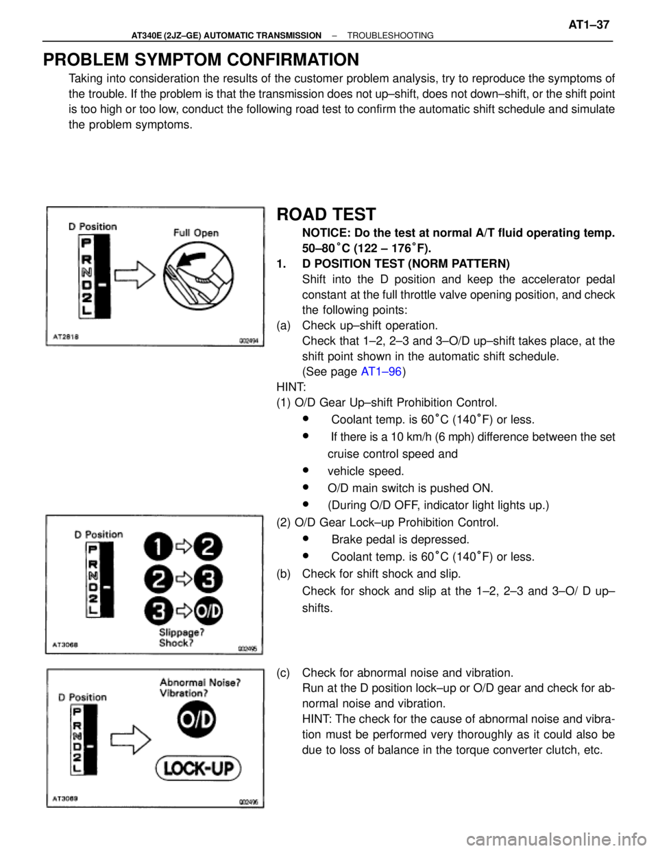
PROBLEM SYMPTOM CONFIRMATION
Taking into consideration the results of the customer problem analysis, try to reproduce the symptoms of
the trouble. If the problem is that the transmission does not up±shift, does not down±shift, or the shift point
is too high or too low, conduct the following road test to confirm the automatic shift schedule and simulate
the problem symptoms.
ROAD TEST
NOTICE: Do the test at normal A/T fluid operating temp.
50±80°C (122 ± 176°F).
1. D POSITION TEST (NORM PATTERN)
Shift into the D position and keep the accelerator pedal
constant at the full throttle valve opening position, and check
the following points:
(a) Check up±shift operation.
Check that 1±2, 2±3 and 3±O/D up±shift takes place, at the
shift point shown in the automatic shift schedule.
(See page AT1±96)
HINT:
(1) O/D Gear Up±shift Prohibition Control.
w Coolant temp. is 60°C (140°F) or less.
w If there is a 10 km/h (6 mph) difference between the set
cruise control speed and
wvehicle speed.
wO/D main switch is pushed ON.
w(During O/D OFF, indicator light lights up.)
(2) O/D Gear Lock±up Prohibition Control.
w Brake pedal is depressed.
w Coolant temp. is 60°C (140°F) or less.
(b) Check for shift shock and slip.
Check for shock and slip at the 1±2, 2±3 and 3±O/ D up±
shifts.
(c) Check for abnormal noise and vibration.
Run at the D position lock±up or O/D gear and check for ab-
normal noise and vibration.
HINT: The check for the cause of abnormal noise and vibra-
tion must be performed very thoroughly as it could also be
due to loss of balance in the torque converter clutch, etc.
± AT340E (2JZ±GE) AUTOMATIC TRANSMISSIONTROUBLESHOOTINGAT1±37
Page 428 of 2543
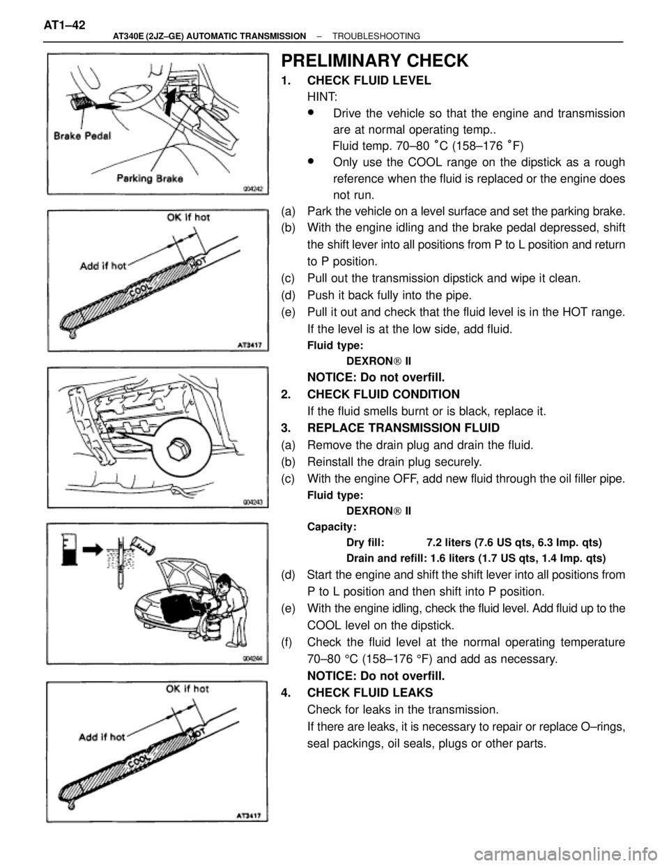
PRELIMINARY CHECK
1. CHECK FLUID LEVEL
HINT:
wDrive the vehicle so that the engine and transmission
are at normal operating temp..
Fluid temp. 70±80 °C (158±176 °F)
wOnly use the COOL range on the dipstick as a rough
reference when the fluid is replaced or the engine does
not run.
(a) Park the vehicle on a level surface and set the parking brake.
(b) With the engine idling and the brake pedal depressed, shift
the shift lever into all positions from P to L position and return
to P position.
(c) Pull out the transmission dipstick and wipe it clean.
(d) Push it back fully into the pipe.
(e) Pull it out and check that the fluid level is in the HOT range.
If the level is at the low side, add fluid.
Fluid type:
DEXRON[ II
NOTICE: Do not overfill.
2. CHECK FLUID CONDITION
If the fluid smells burnt or is black, replace it.
3. REPLACE TRANSMISSION FLUID
(a) Remove the drain plug and drain the fluid.
(b) Reinstall the drain plug securely.
(c) With the engine OFF, add new fluid through the oil filler pipe.
Fluid type:
DEXRON[ II
Capacity:
Dry fill: 7.2 liters (7.6 US qts, 6.3 Imp. qts)
Drain and refill: 1.6 liters (1.7 US qts, 1.4 Imp. qts)
(d) Start the engine and shift the shift lever into all positions from
P to L position and then shift into P position.
(e) With the engine idling, check the fluid level. Add fluid up to the
COOL level on the dipstick.
(f) Check the fluid level at the normal operating temperature
70±80 5C (158±176 5F) and add as necessary.
NOTICE: Do not overfill.
4. CHECK FLUID LEAKS
Check for leaks in the transmission.
If there are leaks, it is necessary to repair or replace O±rings,
seal packings, oil seals, plugs or other parts. AT1±42
± AT340E (2JZ±GE) AUTOMATIC TRANSMISSIONTROUBLESHOOTING
Page 430 of 2543
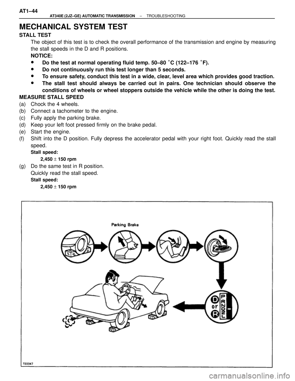
MECHANICAL SYSTEM TEST
STALL TEST
The object of this test is to check the overall performance of the transmission and engine by measuring
the stall speeds in the D and R positions.
NOTICE:
wDo the test at normal operating fluid temp. 50±80 °C (122±176 °F).
wDo not continuously run this test longer than 5 seconds.
wTo ensure safety, conduct this test in a wide, clear, level area which provides good traction.
wThe stall test should always be carried out in pairs. One technician should observe the
conditions of wheels or wheel stoppers outside the vehicle while the other is doing the test.
MEASURE STALL SPEED
(a) Chock the 4 wheels.
(b) Connect a tachometer to the engine.
(c) Fully apply the parking brake.
(d) Keep your left foot pressed firmly on the brake pedal.
(e) Start the engine.
(f) Shift into the D position. Fully depress the accelerator pedal with your right foot. Quickly read the stall
speed.
Stall speed:
2,450 + 150 rpm
(g) Do the same test in R position.
Quickly read the stall speed.
Stall speed:
2,450 + 150 rpm
AT1±44± AT340E (2JZ±GE) AUTOMATIC TRANSMISSIONTROUBLESHOOTING