Page 58 of 2248
3. RELATED PARTS
1) Install valve rocker assembly.
B2M0418B
Tightening torque: N⋅m (kg-m, ft-lb)
T1: 5±1 (0.5±0.1, 3.6±0.7)
T2: 12±1 (1.2±0.1, 8.7±0.7)
2) Install timing belt, camshaft sprockets and related parts.
6. Cylinder Head
A: REMOVAL
1. INTAKE MANIFOLD
1) Release fuel pressure.
2) Drain engine coolant.
3) Remove intake manifold.
4) Remove engine coolant pipe.
38
2-3SERVICE PROCEDURE
5. Camshaft - 6. Cylinder Head
Page 59 of 2248
3. RELATED PARTS
1) Install valve rocker assembly.
B2M0418B
Tightening torque: N⋅m (kg-m, ft-lb)
T1: 5±1 (0.5±0.1, 3.6±0.7)
T2: 12±1 (1.2±0.1, 8.7±0.7)
2) Install timing belt, camshaft sprockets and related parts.
6. Cylinder Head
A: REMOVAL
1. INTAKE MANIFOLD
1) Release fuel pressure.
2) Drain engine coolant.
3) Remove intake manifold.
4) Remove engine coolant pipe.
38
2-3SERVICE PROCEDURE
5. Camshaft - 6. Cylinder Head
Page 123 of 2248
G6M0095
2. Engine Coolant Pump
A: REMOVAL
1) Open engine hood.
2) Disconnect ground cable from the battery.
B2M0015A
3) Drain engine coolant completely.
B2M0137
4) Disconnect radiator outlet hose from engine coolant
pump.
B2M0323
5) Remove radiator fan motor assembly.
G2M0286
6) Remove V-belt(s).
8
2-5SERVICE PROCEDURE
2. Engine Coolant Pump
Page 133 of 2248
B2M0323
5) Remove radiator fan motor assembly.
6) Remove fan motor from shroud.
B: INSTALLATION
Installation is in the reverse order of removal procedures.
Do the following:
1) Before installing radiator fan motor, apply a coat of seal-
ant to threads and tighten nuts.
2) Make sure radiator fan does not come into contact with
shroud when installed.
3) After installation, make sure there is no unusual noise
or vibration when fan is rotated.
G6M0095
7. Engine Coolant Pipe
A: REMOVAL
1) Release fuel pressure.
2) Disconnect ground cable from the battery.
B2M0015A
3) Drain engine coolant completely.
B2M0160
4) Remove intake manifold.
16
2-5SERVICE PROCEDURE
6. Radiator Fan and Fan Motor - 7. Engine Coolant Pipe
Page 134 of 2248
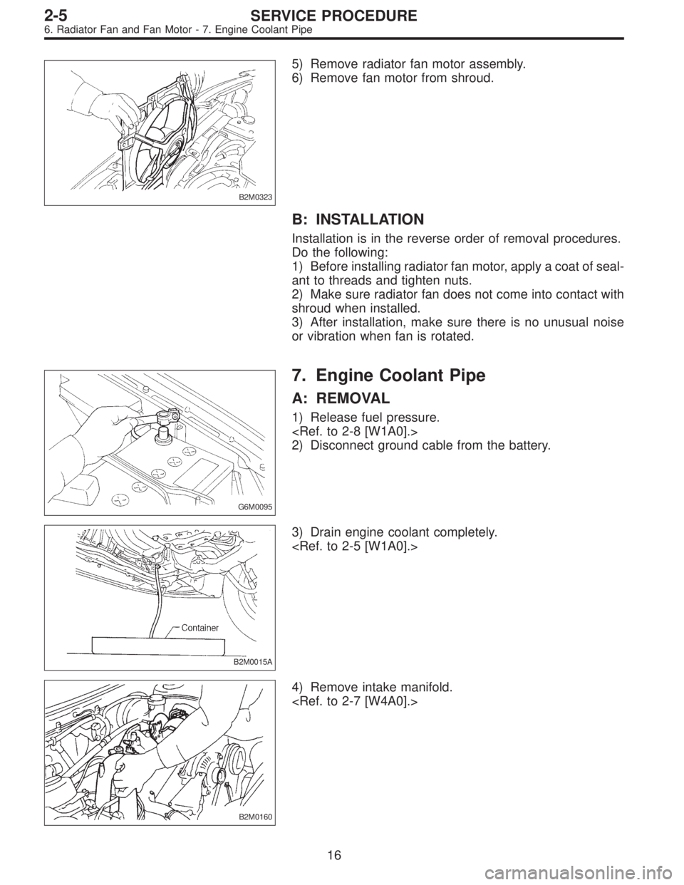
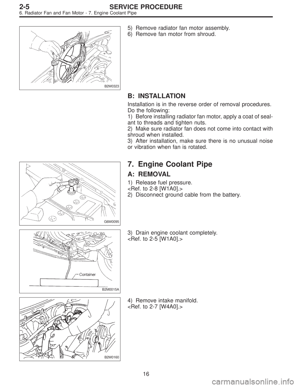
B2M0323
5) Remove radiator fan motor assembly.
6) Remove fan motor from shroud.
B: INSTALLATION
Installation is in the reverse order of removal procedures.
Do the following:
1) Before installing radiator fan motor, apply a coat of seal-
ant to threads and tighten nuts.
2) Make sure radiator fan does not come into contact with
shroud when installed.
3) After installation, make sure there is no unusual noise
or vibration when fan is rotated.
G6M0095
7. Engine Coolant Pipe
A: REMOVAL
1) Release fuel pressure.
2) Disconnect ground cable from the battery.
B2M0015A
3) Drain engine coolant completely.
B2M0160
4) Remove intake manifold.
16
2-5SERVICE PROCEDURE
6. Radiator Fan and Fan Motor - 7. Engine Coolant Pipe
Page 159 of 2248
B2M0154
4. Intake Manifold
A: REMOVAL
1) Release fuel pressure.
2) Disconnect connector from mass air flow sensor.
3) Remove air intake duct, air cleaner upper cover and air
cleaner element.
G2M0280
4) Disconnect accelerator cable�1.
5) Disconnect cruise control cable�
2. (With cruise control
model)
B2M0334
6) Disconnect hoses from pressure sources switching
solenoid valve.
G2M0286
7) Remove power steering pump from bracket.
(1) Loosen lock bolt and slider bolt, and remove front
side V-belt.
B2M0340
(2) Remove pipe with bracket from intake manifold.
8
2-7SERVICE PROCEDURE
4. Intake Manifold
Page 180 of 2248
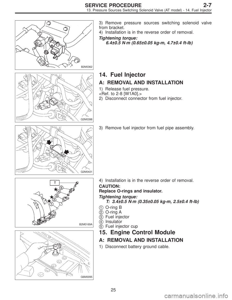
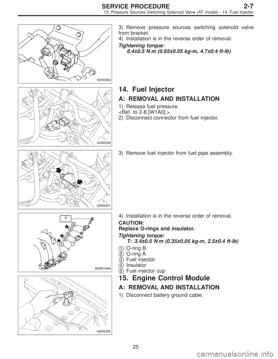
B2M0362
3) Remove pressure sources switching solenoid valve
from bracket.
4) Installation is in the reverse order of removal.
Tightening torque:
6.4±0.5 N⋅m (0.65±0.05 kg-m, 4.7±0.4 ft-lb)
G2M0398
14. Fuel Injector
A: REMOVAL AND INSTALLATION
1) Release fuel pressure.
2) Disconnect connector from fuel injector.
G2M0431
3) Remove fuel injector from fuel pipe assembly.
B2M0169A
4) Installation is in the reverse order of removal.
CAUTION:
Replace O-rings and insulator.
Tightening torque:
T: 3.4±0.5 N⋅m (0.35±0.05 kg-m, 2.5±0.4 ft-lb)
�
1O-ring B
�
2O-ring A
�
3Fuel injector
�
4Insulator
�
5Fuel injector cup
G6M0095
15. Engine Control Module
A: REMOVAL AND INSTALLATION
1) Disconnect battery ground cable.
25
2-7SERVICE PROCEDURE
13. Pressure Sources Switching Solenoid Valve (AT model) - 14. Fuel Injector
Page 181 of 2248
B2M0362
3) Remove pressure sources switching solenoid valve
from bracket.
4) Installation is in the reverse order of removal.
Tightening torque:
6.4±0.5 N⋅m (0.65±0.05 kg-m, 4.7±0.4 ft-lb)
G2M0398
14. Fuel Injector
A: REMOVAL AND INSTALLATION
1) Release fuel pressure.
2) Disconnect connector from fuel injector.
G2M0431
3) Remove fuel injector from fuel pipe assembly.
B2M0169A
4) Installation is in the reverse order of removal.
CAUTION:
Replace O-rings and insulator.
Tightening torque:
T: 3.4±0.5 N⋅m (0.35±0.05 kg-m, 2.5±0.4 ft-lb)
�
1O-ring B
�
2O-ring A
�
3Fuel injector
�
4Insulator
�
5Fuel injector cup
G6M0095
15. Engine Control Module
A: REMOVAL AND INSTALLATION
1) Disconnect battery ground cable.
25
2-7SERVICE PROCEDURE
13. Pressure Sources Switching Solenoid Valve (AT model) - 14. Fuel Injector
![SUBARU LEGACY 1995 Service Repair Manual 3. RELATED PARTS
1) Install valve rocker assembly.
<Ref. to 2-3 [W4E0].>
B2M0418B
Tightening torque: N⋅m (kg-m, ft-lb)
T1: 5±1 (0.5±0.1, 3.6±0.7)
T2: 12±1 (1.2±0.1, 8.7±0.7)
2) Install timing](/manual-img/17/57432/w960_57432-57.png "SUBARU LEGACY 1995 Service Repair Manual 3. RELATED PARTS
1) Install valve rocker assembly.
<Ref. to 2-3 [W4E0].>
B2M0418B
Tightening torque: N⋅m (kg-m, ft-lb)
T1: 5±1 (0.5±0.1, 3.6±0.7)
T2: 12±1 (1.2±0.1, 8.7±0.7)
2) Install timing")
![SUBARU LEGACY 1995 Service Repair Manual 3. RELATED PARTS
1) Install valve rocker assembly.
<Ref. to 2-3 [W4E0].>
B2M0418B
Tightening torque: N⋅m (kg-m, ft-lb)
T1: 5±1 (0.5±0.1, 3.6±0.7)
T2: 12±1 (1.2±0.1, 8.7±0.7)
2) Install timing](/manual-img/17/57432/w960_57432-58.png "SUBARU LEGACY 1995 Service Repair Manual 3. RELATED PARTS
1) Install valve rocker assembly.
<Ref. to 2-3 [W4E0].>
B2M0418B
Tightening torque: N⋅m (kg-m, ft-lb)
T1: 5±1 (0.5±0.1, 3.6±0.7)
T2: 12±1 (1.2±0.1, 8.7±0.7)
2) Install timing")
![SUBARU LEGACY 1995 Service Repair Manual G6M0095
2. Engine Coolant Pump
A: REMOVAL
1) Open engine hood.
2) Disconnect ground cable from the battery.
B2M0015A
3) Drain engine coolant completely.
<Ref. to 2-5 [W1A0].>
B2M0137
4) Disconnect rad](/manual-img/17/57432/w960_57432-122.png "SUBARU LEGACY 1995 Service Repair Manual G6M0095
2. Engine Coolant Pump
A: REMOVAL
1) Open engine hood.
2) Disconnect ground cable from the battery.
B2M0015A
3) Drain engine coolant completely.
<Ref. to 2-5 [W1A0].>
B2M0137
4) Disconnect rad")
![SUBARU LEGACY 1995 Service Repair Manual B2M0154
4. Intake Manifold
A: REMOVAL
1) Release fuel pressure. <Ref. to 2-8 [W1A0].>
2) Disconnect connector from mass air flow sensor.
3) Remove air intake duct, air cleaner upper cover and air
clea](/manual-img/17/57432/w960_57432-158.png "SUBARU LEGACY 1995 Service Repair Manual B2M0154
4. Intake Manifold
A: REMOVAL
1) Release fuel pressure. <Ref. to 2-8 [W1A0].>
2) Disconnect connector from mass air flow sensor.
3) Remove air intake duct, air cleaner upper cover and air
clea")