Page 393 of 2248
B3M0113
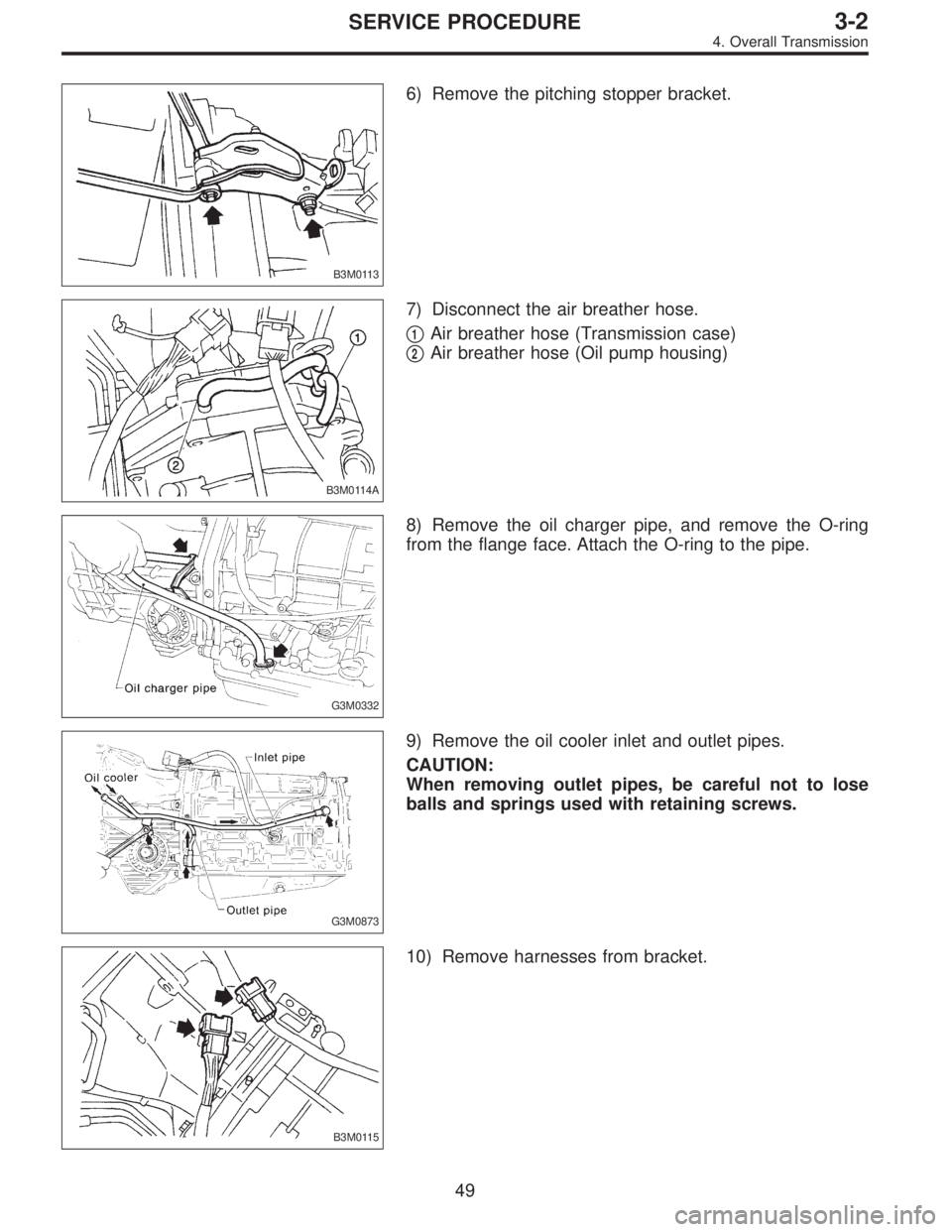
6) Remove the pitching stopper bracket.
B3M0114A
7) Disconnect the air breather hose.
�
1Air breather hose (Transmission case)
�
2Air breather hose (Oil pump housing)
G3M0332
8) Remove the oil charger pipe, and remove the O-ring
from the flange face. Attach the O-ring to the pipe.
G3M0873
9) Remove the oil cooler inlet and outlet pipes.
CAUTION:
When removing outlet pipes, be careful not to lose
balls and springs used with retaining screws.
B3M0115
10) Remove harnesses from bracket.
49
3-2SERVICE PROCEDURE
4. Overall Transmission
Page 394 of 2248
G3M0874
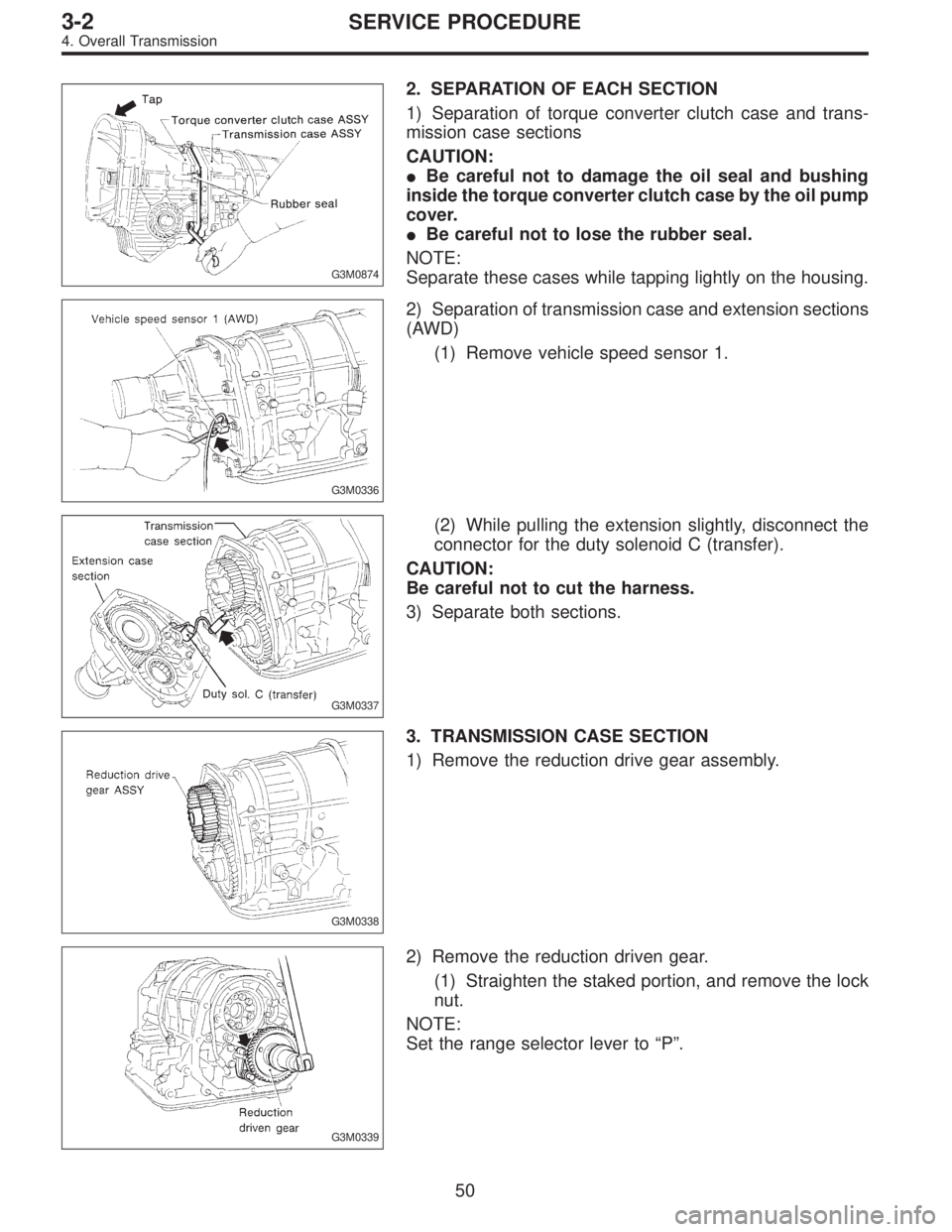
2. SEPARATION OF EACH SECTION
1) Separation of torque converter clutch case and trans-
mission case sections
CAUTION:
�Be careful not to damage the oil seal and bushing
inside the torque converter clutch case by the oil pump
cover.
�Be careful not to lose the rubber seal.
NOTE:
Separate these cases while tapping lightly on the housing.
G3M0336
2) Separation of transmission case and extension sections
(AWD)
(1) Remove vehicle speed sensor 1.
G3M0337
(2) While pulling the extension slightly, disconnect the
connector for the duty solenoid C (transfer).
CAUTION:
Be careful not to cut the harness.
3) Separate both sections.
G3M0338
3. TRANSMISSION CASE SECTION
1) Remove the reduction drive gear assembly.
G3M0339
2) Remove the reduction driven gear.
(1) Straighten the staked portion, and remove the lock
nut.
NOTE:
Set the range selector lever to“P”.
50
3-2SERVICE PROCEDURE
4. Overall Transmission
Page 395 of 2248
G3M0340
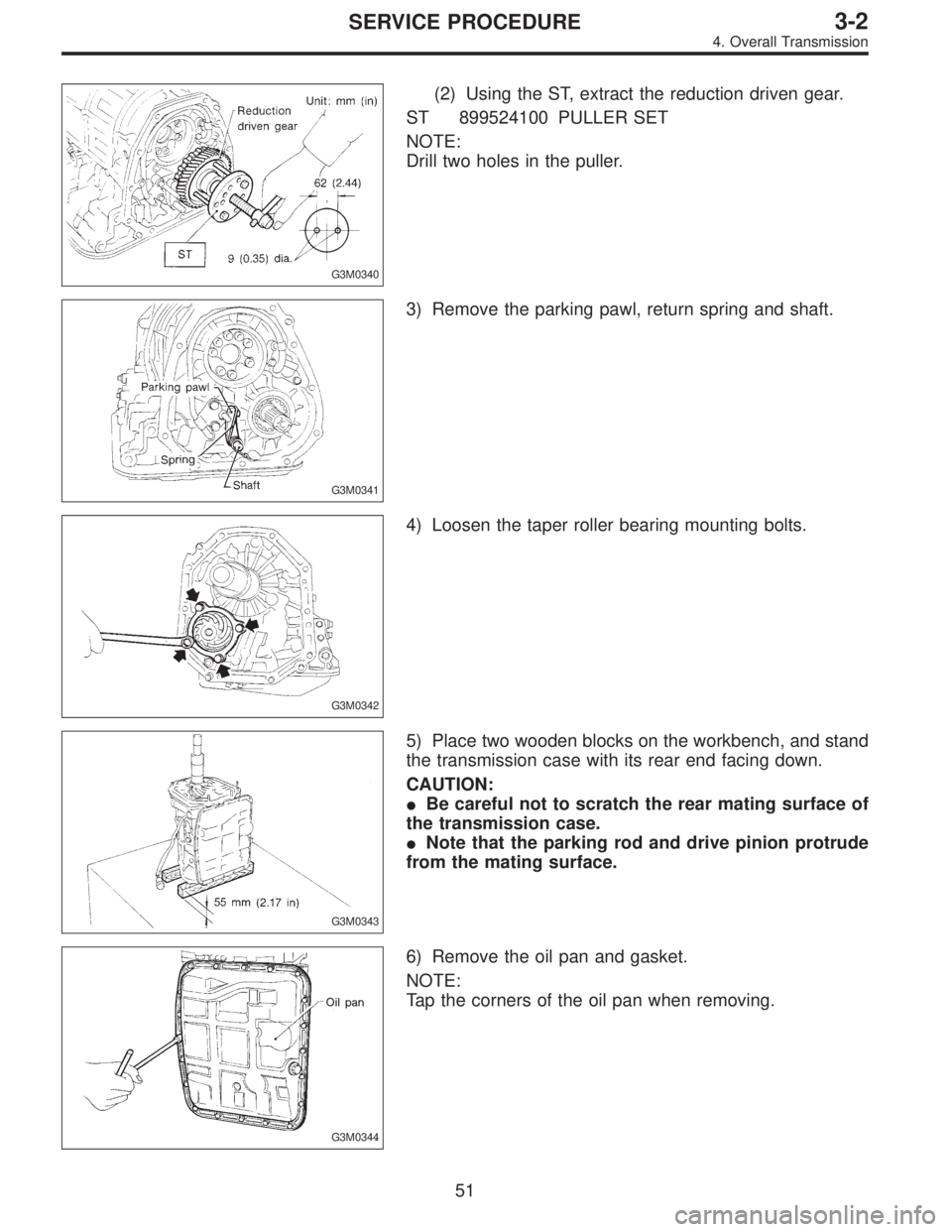
(2) Using the ST, extract the reduction driven gear.
ST 899524100 PULLER SET
NOTE:
Drill two holes in the puller.
G3M0341
3) Remove the parking pawl, return spring and shaft.
G3M0342
4) Loosen the taper roller bearing mounting bolts.
G3M0343
5) Place two wooden blocks on the workbench, and stand
the transmission case with its rear end facing down.
CAUTION:
�Be careful not to scratch the rear mating surface of
the transmission case.
�Note that the parking rod and drive pinion protrude
from the mating surface.
G3M0344
6) Remove the oil pan and gasket.
NOTE:
Tap the corners of the oil pan when removing.
51
3-2SERVICE PROCEDURE
4. Overall Transmission
Page 396 of 2248
G3M0345
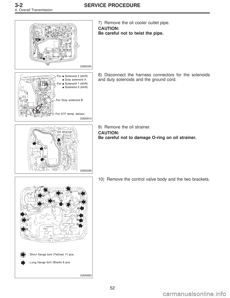
7) Remove the oil cooler outlet pipe.
CAUTION:
Be careful not to twist the pipe.
G3M0915
8) Disconnect the harness connectors for the solenoids
and duty solenoids and the ground cord.
G3M0299
9) Remove the oil strainer.
CAUTION:
Be careful not to damage O-ring on oil strainer.
G3M0863
10) Remove the control valve body and the two brackets.
52
3-2SERVICE PROCEDURE
4. Overall Transmission
Page 397 of 2248
G3M0346
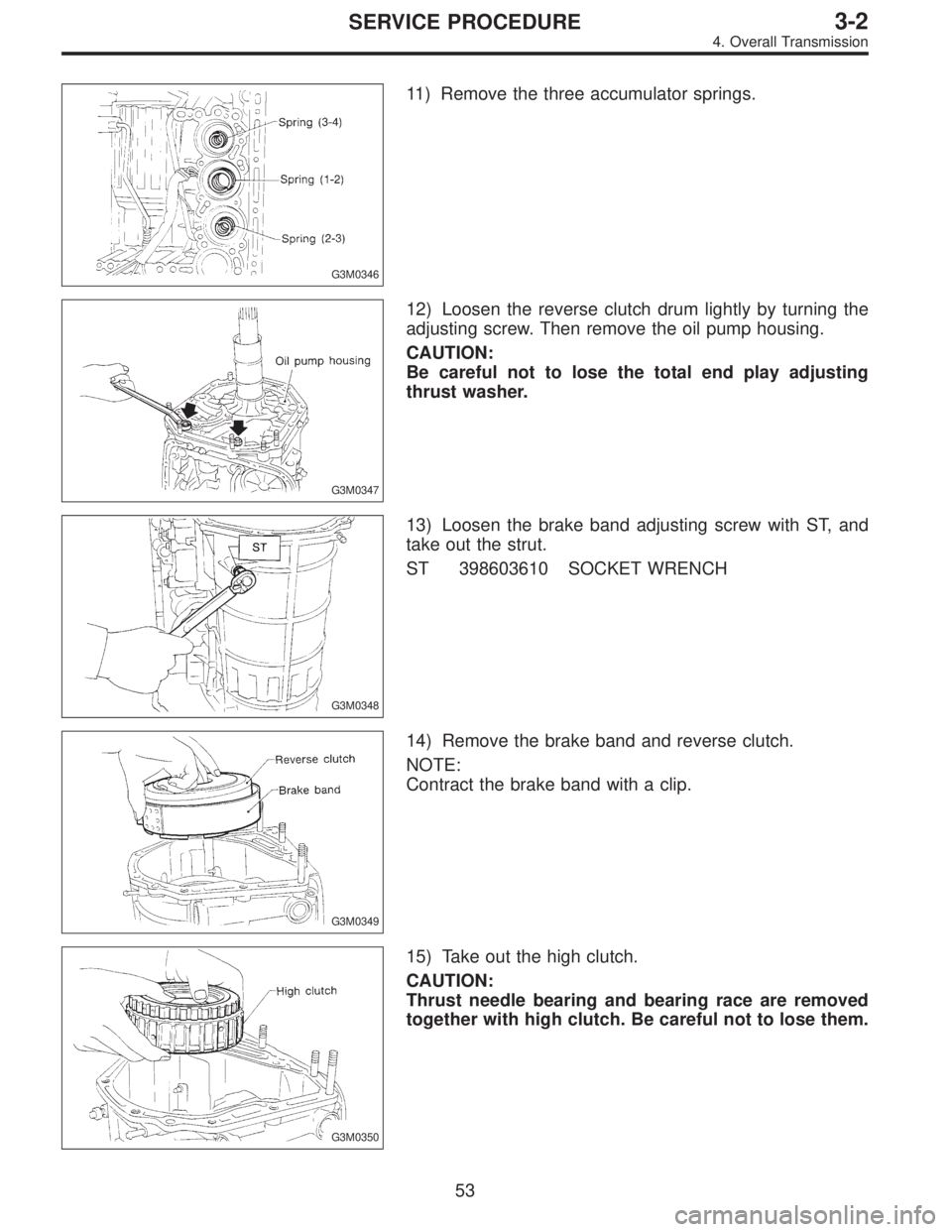
11) Remove the three accumulator springs.
G3M0347
12) Loosen the reverse clutch drum lightly by turning the
adjusting screw. Then remove the oil pump housing.
CAUTION:
Be careful not to lose the total end play adjusting
thrust washer.
G3M0348
13) Loosen the brake band adjusting screw with ST, and
take out the strut.
ST 398603610 SOCKET WRENCH
G3M0349
14) Remove the brake band and reverse clutch.
NOTE:
Contract the brake band with a clip.
G3M0350
15) Take out the high clutch.
CAUTION:
Thrust needle bearing and bearing race are removed
together with high clutch. Be careful not to lose them.
53
3-2SERVICE PROCEDURE
4. Overall Transmission
Page 400 of 2248
G3M0361
(3) Take out the low & reverse piston by applying com-
pressed air.
G3M0362
25) After removing the snap ring (inner), take out the servo
piston by applying compressed air from the release pres-
sure side.
CAUTION:
Hold the servo piston with a rag so that it will not be
ejected with the air pressure. In this case, do not allow
your finger to be pinched between the pipe and
retainer.
B3M0351A
26) Apply compressed air from the operating pressure
side, and take out accumulator (3-4), accumulator (1-2),
accumulator (2-3), accumulator and spring (N-D).
G3M0364
27) Remove the range select lever.
28) Remove the detention spring.
G3M0365
29) Remove the parking rod together with the manual
lever. Then remove the manual shaft by pulling off the
straight pin.
CAUTION:
Be careful not to damage the lips of the press-fitted oil
seal in the case.
56
3-2SERVICE PROCEDURE
4. Overall Transmission
Page 402 of 2248
G3M0371
5) Remove the snap ring. Then remove the speedometer
driven gear.
G3M0372
6) Remove vehicle speed sensor 2.
7) Tap out the speedometer shaft to the outside of the
case, and remove the oil seal.
G3M0373
5. EXTENSION SECTION
1) Take out the transfer clutch by lightly tapping the end of
the rear drive shaft.
CAUTION:
Be careful not to damage the oil seal in the extension.
G3M0867
2) Remove duty solenoid C, transfer valve body and the
transfer pipe.
CAUTION:
�Take out the inlet filter.
�Do not damage the O-ring.
�Be careful not to bend the pipe.
B3M0831A
3) Take out the roller bearing inner race with ST.
ST 398527700 PULLER
4) Take out the roller bearing outer race with ST.
NOTE:
Hook ST in the inner side of the roller bearing outer race.
ST 398527700 PULLER
58
3-2SERVICE PROCEDURE
4. Overall Transmission
Page 403 of 2248
B: ASSEMBLY OF OVERALL TRANSMISSION
1. TORQUE CONVERTER CLUTCH CASE SECTION
1) Check the appearance of each component and clean.
CAUTION:
Make sure each part is free of harmful cuts, damage
and other faults.
G3M0377
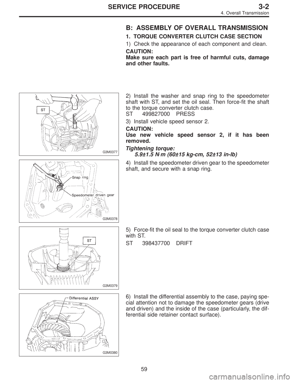
2) Install the washer and snap ring to the speedometer
shaft with ST, and set the oil seal. Then force-fit the shaft
to the torque converter clutch case.
ST 499827000 PRESS
3) Install vehicle speed sensor 2.
CAUTION:
Use new vehicle speed sensor 2, if it has been
removed.
Tightening torque:
5.9±1.5 N⋅m (60±15 kg-cm, 52±13 in-lb)
G3M0378
4) Install the speedometer driven gear to the speedometer
shaft, and secure with a snap ring.
G3M0379
5) Force-fit the oil seal to the torque converter clutch case
with ST.
ST 398437700 DRIFT
G3M0380
6) Install the differential assembly to the case, paying spe-
cial attention not to damage the speedometer gears (drive
and driven) and the inside of the case (particularly, the dif-
ferential side retainer contact surface).
59
3-2SERVICE PROCEDURE
4. Overall Transmission