Page 429 of 2248

6. Control Valve Body
The control valve is composed of parts which are accu-
rately machined to a high degree and should be handled
carefully during disassembly and assembly. As these parts
are similar in shape, they should be arranged in neat order
on a table after disassembly so that they can be easily
installed to their original positions. Spring loaded parts
should be also handled carefully, as springs may jump out
of place when the parts are disassembled or removed.
Extreme care should be taken so as not to drop valves on
the floor. Before assembling, the parts and valves should
be dipped in a container filled with the ATF. Make sure that
the valves are clean and free from any foreign material
before assembly. Torque specifications should also be
observed.
G3M0899
�1Lock-up control sleeve
�
2Lock-up control plug
�
3Lock-up control valve
�
4Pilot valve
�
5Pressure regulator valve
�
6Pressure regulator plug
�
7Torque converter regulation valve
�
8Pressure regulator sleeve plug
�
9Accumulator control sleeve
�
10Accumulator control plug
�
11Shuttle duty shift valve
�
124-2 sequence valve
�
13Pressure modifier valve
�
14Shift valve B
�
154-2 relay valve
�
16Shift valve A
�
17Overrunning clutch control valve�
18Overrunning clutch reducing valve
�
19Shuttle shift valve
�
20Manual valve
�
21Forward clutch control valve
�
221st reducing valve
�
233-2 timing valve
�
24Servo charger valve
�
25Pressure regulator spring
�
26Pressure modifier spring
�
27Modifier accumulator spring
�
28Pilot spring
�
29Accumulator control spring
�
30Shift B spring
�
31Shift A spring
�
32Shuttle shift spring
�
33Overrunning clutch control spring
�
344-2 sequence spring�
354-2 relay spring
�
36Servo charger spring
�
373-2 timing spring
�
381st reducing spring
�
39Overrunning clutch reducing spring
�
40Torque converter regulator spring
�
41Lock-up control spring
�
42Shuttle duty shift spring
85
3-2SERVICE PROCEDURE
6. Control Valve Body
Page 430 of 2248

No. Part name Wire dia. Outer dia. Effective turn Free length
25 Pressure regulator spring 1.6 (0.063) 14.0 (0.551) 5.6 31.5 (1.240)
26 Pressure modifier spring 0.8 (0.031) 6.8 (0.268) 1")
Unit: mm (in)
No. Part name Wire dia. Outer dia. Effective turn Free length
25 Pressure regulator spring 1.6 (0.063) 14.0 (0.551) 5.6 31.5 (1.240)
26 Pressure modifier spring 0.8 (0.031) 6.8 (0.268) 10.0 31.95 (1.2579)
27 Modifier accumulator spring 1.3 (0.051) 9.8 (0.386) 8.8 30.5 (1.201)
28 Pilot spring 1.1 (0.043) 9.1 (0.358) 8.3 25.7 (1.012)
29 Accumulator control spring 0.4 (0.016) 6.6 (0.260) 11.0 27.5 (1.083)
30 Shift B spring 0.65 (0.0256) 7.0 (0.276) 9.5 25.0 (0.984)
31 Shift A spring 0.5 (0.020) 7.0 (0.276) 9.5 25.0 (0.984)
32 Shuttle shift spring 0.65 (0.0256) 5.65 (0.2224) 27.6 51.0 (2.008)
33 Overrunning clutch control spring 0.7 (0.028) 6.0 (0.236) 12.0 26.5 (1.043)
34 4-2 sequence spring 0.55 (0.0217) 6.95 (0.2736) 11.0 29.1 (1.146)
35 4-2 relay spring 0.55 (0.0217) 6.95 (0.2736) 11.0 29.1 (1.146)
36 Servo charger spring 0.7 (0.028) 6.7 (0.264) 9.0 23.0 (0.906)
37 3-2 timing spring 0.75 (0.0295) 6.75 (0.2657) 7.5 20.55 (0.8091)
38 1st reducing spring 0.75 (0.0295) 6.75 (0.2657) 12.5 25.4 (1.000)
39 Overrunning clutch reducing spring 1.05 (0.0413) 7.05 (0.2776) 15.21 34.7 (1.366)
40 Torque converter regulator spring 1.3 (0.051) 9.0 (0.354) 11.7 38.0 (1.496)
41 Lock-up control spring 0.75 (0.0295) 13.0 (0.512) 3.5 18.5 (0.728)
42 Shuttle duty shift spring 0.75 (0.0295) 5.65 (0.2224) 27.6 51.0 (2.008)
86
3-2SERVICE PROCEDURE
6. Control Valve Body
Page 729 of 2248
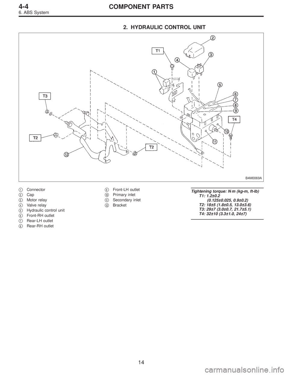
2. HYDRAULIC CONTROL UNIT
B4M0069A
�1Connector
�
2Cap
�
3Motor relay
�
4Valve relay
�
5Hydraulic control unit
�
6Front-RH outlet
�
7Rear-LH outlet
�
8Rear-RH outlet�
9Front-LH outlet
�
10Primary inlet
�
11Secondary inlet
�
12Bracket
Tightening torque: N⋅m (kg-m, ft-lb)
T1: 1.2±0.2
(0.125±0.025, 0.9±0.2)
T2: 18±5 (1.8±0.5, 13.0±3.6)
T3: 29±7 (3.0±0.7, 21.7±5.1)
T4: 32±10 (3.3±1.0, 24±7)
14
4-4COMPONENT PARTS
6. ABS System
Page 733 of 2248
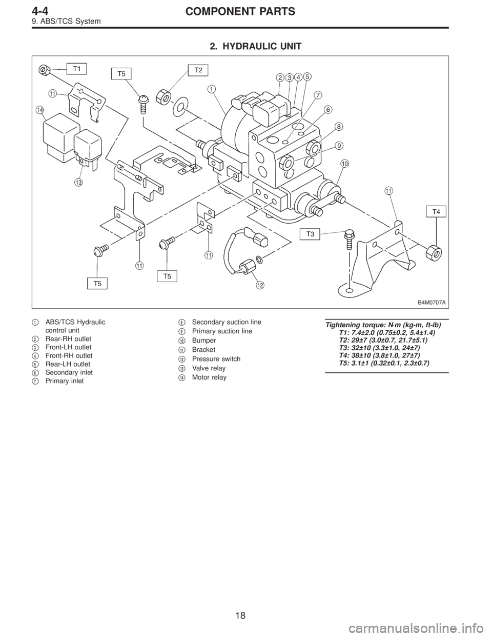
2. HYDRAULIC UNIT
B4M0707A
�1ABS/TCS Hydraulic
control unit
�
2Rear-RH outlet
�
3Front-LH outlet
�
4Front-RH outlet
�
5Rear-LH outlet
�
6Secondary inlet
�
7Primary inlet�
8Secondary suction line
�
9Primary suction line
�
10Bumper
�
11Bracket
�
12Pressure switch
�
13Valve relay
�
14Motor relay
Tightening torque: N⋅m (kg-m, ft-lb)
T1: 7.4±2.0 (0.75±0.2, 5.4±1.4)
T2: 29±7 (3.0±0.7, 21.7±5.1)
T3: 32±10 (3.3±1.0, 24±7)
T4: 38±10 (3.8±1.0, 27±7)
T5: 3.1±1 (0.32±0.1, 2.3±0.7)
18
4-4COMPONENT PARTS
9. ABS/TCS System
Page 783 of 2248

15. Hydraulic Unit for ABS System
B4M0069A
�1Connector
�
2Cap
�
3Motor relay
�
4Valve relay
�
5Hydraulic control unit
�
6Front-RH outlet
�
7Rear-LH outlet�
8Rear-RH outlet
�
9Front-LH outlet
�
10Primary inlet
�
11Secondary inlet
�
12Bracket
Tightening torque: N⋅m (kg-m, ft-lb)
T1: 1.2±0.2
(0.125±0.025, 0.9±0.2)
T2: 18±5 (1.8±0.5, 13.0±3.6)
T3: 29±7 (3.0±0.7, 21.7±5.1)
T4: 32±10 (3.3±1.0, 24±7)
A: REMOVAL
1) Remove air intake duct.
2) Remove canister from engine compartment to facilitate
removal of hydraulic unit.
3) Disconnect brake pipes from hydraulic unit and plug
open joints to prevent entry of foreign particles.
G4M0455
4) Remove nuts and bolts which secure hydraulic unit, and
remove hydraulic unit from engine compartment.
CAUTION:
�Hydraulic unit cannot be disassembled. Do not
attempt to loosen bolts and nuts.
�Do not drop or bump hydraulic unit.
�Do not turn the hydraulic unit upside down or place
it on its side.
66
4-4SERVICE PROCEDURE
15. Hydraulic Unit for ABS System
Page 784 of 2248
�Be careful to prevent foreign particles from getting into
hydraulic unit.
�When a new hydraulic unit is installed, apply a coat of
rust-preventive wax (Nippeco LT or GB) to bracket attach-
ing bolts after tightening.
�Do not pull harness disconnecting harness connector.
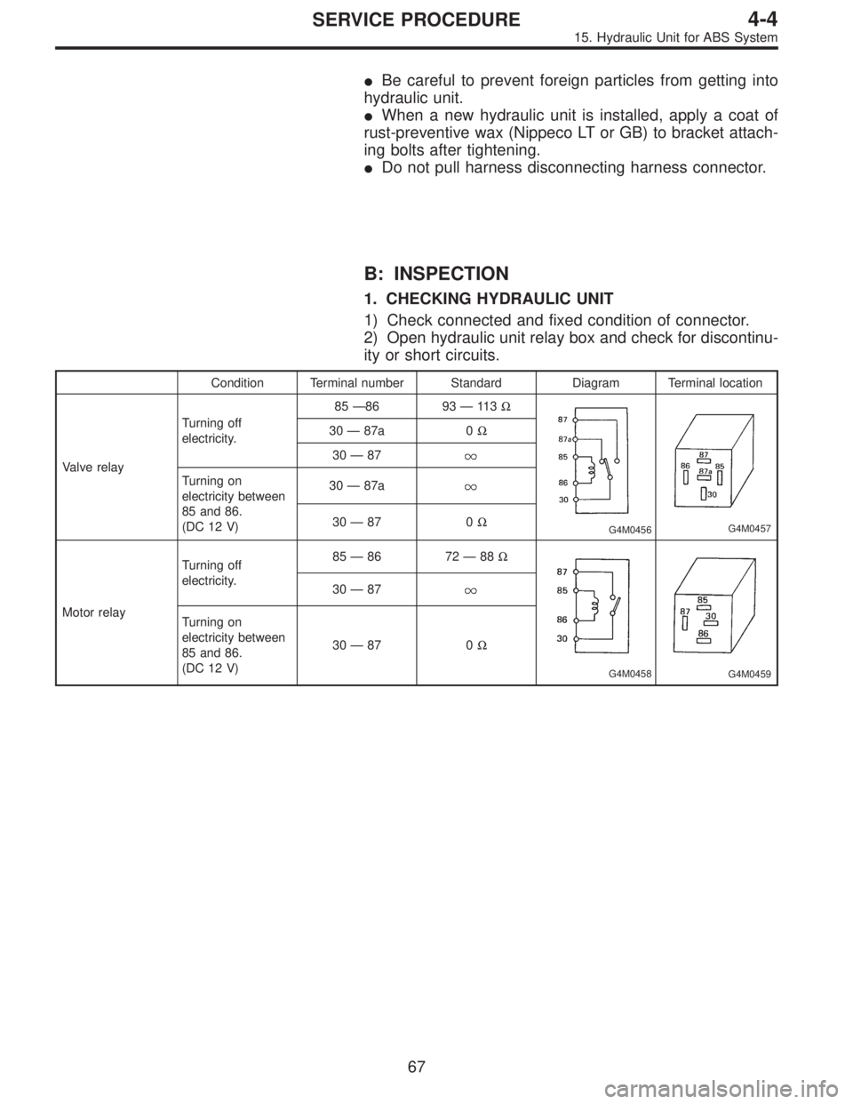
B: INSPECTION
1. CHECKING HYDRAULIC UNIT
1) Check connected and fixed condition of connector.
2) Open hydraulic unit relay box and check for discontinu-
ity or short circuits.
Condition Terminal number Standard Diagram Terminal location
Valve relayTurning off
electricity.85—86 93—11 3Ω
G4M0456G4M0457
30—87a 0Ω
30—87
Turning on
electricity between
85 and 86.
(DC 12 V)30—87a
30—87 0Ω
Motor relayTurning off
electricity.85—86 72—88Ω
G4M0458G4M0459
30—87
Turning on
electricity between
85 and 86.
(DC 12 V)30—87 0Ω
67
4-4SERVICE PROCEDURE
15. Hydraulic Unit for ABS System
Page 790 of 2248
G4M0455
D: INSTALLATION
1) Install relay box cover on hydraulic unit.
2) Install hydraulic unit to bracket.
Tightening torque:
18±5 N⋅m (1.8±0.5 kg-m, 13.0±3.6 ft-lb)
3) Tighten bracket and motor ground lead as a unit.
Tightening torque:
32±10 N⋅m (3.3±1.0 kg-m, 24±7 ft-lb)
4) Connect brake pipes to their correct hydraulic unit con-
nections.
Tightening torque:
15
+3
�2N⋅m (1.5+0.3
�0.2kg-m, 10.8+2.2
�1.4ft-lb)
16. ABS Control Module
A: REMOVAL
1) Remove floor mat located under lower right side of front
seat.
G4M0468
2) Remove screw which secure ABS control module from
the body.
G4M0469
3) Disconnect connector from ABS control module.
73
4-4SERVICE PROCEDURE
15. Hydraulic Unit for ABS System - 16. ABS Control Module
Page 791 of 2248
G4M0455
D: INSTALLATION
1) Install relay box cover on hydraulic unit.
2) Install hydraulic unit to bracket.
Tightening torque:
18±5 N⋅m (1.8±0.5 kg-m, 13.0±3.6 ft-lb)
3) Tighten bracket and motor ground lead as a unit.
Tightening torque:
32±10 N⋅m (3.3±1.0 kg-m, 24±7 ft-lb)
4) Connect brake pipes to their correct hydraulic unit con-
nections.
Tightening torque:
15
+3
�2N⋅m (1.5+0.3
�0.2kg-m, 10.8+2.2
�1.4ft-lb)
16. ABS Control Module
A: REMOVAL
1) Remove floor mat located under lower right side of front
seat.
G4M0468
2) Remove screw which secure ABS control module from
the body.
G4M0469
3) Disconnect connector from ABS control module.
73
4-4SERVICE PROCEDURE
15. Hydraulic Unit for ABS System - 16. ABS Control Module
 Install relay box cover on hydraulic unit.
2) Install hydraulic unit to bracket.
Tightening torque:
18±5 N⋅m (1.8±0.5 kg-m, 13.0±3.6 ft-lb)
3) Tighten bracket and motor")
 Install relay box cover on hydraulic unit.
2) Install hydraulic unit to bracket.
Tightening torque:
18±5 N⋅m (1.8±0.5 kg-m, 13.0±3.6 ft-lb)
3) Tighten bracket and motor")