Page 1639 of 1701
SUPPLEMENTALRESTRAINTSYSTEM(SRS)
Disposal ofAir Bag Module andSeat Belt
Pre-tensioner
• Before disposing ofair bag module andseat beltpre-tensioner, orvehicles equipped withsuch
systems, deploythesystems. Ifsuch systems havealready beendeployed duetoan accident, dis-
pose ofas indicated in"DISPOSING OFAIR BAG MODULE ANDSEAT BELTPRE-TENSIONER" (RS-
24).
• When deploying theairbag module, alwaysusetheSpecial Service Tool;Deployment tool
KV99106400.
• When deploying theairbag module andseat beltpre-tensioner, standatleast 5m (16 ft)away from
the deployment component.
• Due toheat, leave airbag module unattended formore than30minutes afterdeployment. Alsoleave
seat beltpre-tensioner unattendedformore than10minutes afterdeployment.
• Besure towear gloves whenhandling adeployed airbag module andseat beltpre-tensioner.
• Never applywater toadeployed airbag module.
• Wash yourhands cleanafterfinishing- work.
• Donot dispose ofthe airbag module andseat beltpre-tensioner un-deployed.
CHECKING DEPLOYMENT TOOL
Connecting tobattery
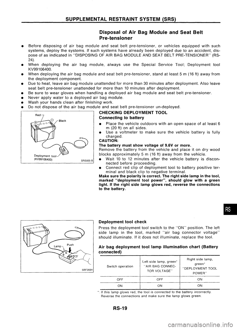
• Place thevehicle outdoors withanopen space ofat least 6
m (20
ft)
on allsides.
• Use avoltmeter tomake surethevehicle batteryisfully
charged.
CAUTION:
The battery mustshow voltage of9.6V ormore.
Remove thebattery fromthevehicle andplace iton dry wood
Deployment
tool blocksapproximately 5m (16 ft)away fromthevehicle.
(KV99106400j SRS005-B•
Wait 10to12 minutes afterthevehicle batteryisdiscon-
nected beforeproceeding.
• Connect redclip ofdeployment tooltobattery positive ter-
minal andblack cliptonegative terminal.
Make surethepolarity iscorrect. Theright sidelamp inthe tool,
marked "deployment toolpower", shouldglowwithagreen
light. Ifthe right sidelamp glows red,reverse theconnections
to the battery.
•
SBF266H Deployment
toolcheck
Press thedeployment toolswitch tothe "ON" position. Theleft
side lamp inthe tool, marked "airbagconnector voltage"
should illuminate.
If
it
does notilluminate, replacethetool.
Air bag deployment toollamp illumination chart(Battery
connected)
Leftside lamp, green' RighI
sidelamp,
Switch operation "AIR
BAGCONNEC- green'
"DEPLOYMENT TOOL
TOR VOLTAGE"
POWER"
OFF OFF ON
ON ON
ON
,. Ifthis lamp glows red,the1001 isconnecled tothe battery incorrectly.
Reverse theconnections andmake surethelamp glows green.
RS-19
Page 1640 of 1701
"'-Passenger airbag bracket
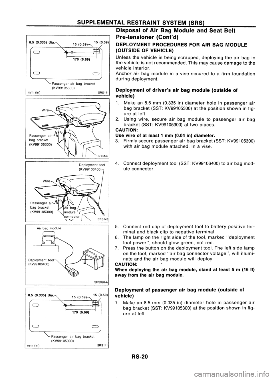
(KV99105300) Deploymentofdriver's airbag module (outside of
vehicle)
1. Make an8.5 mm (0.335 in)diameter holeinpassenger air
bag bracket (SST:KV99105300) atthe position showninfig-
ure atleft.
2. Using wire,secure airbag module topassenger airbag
bracket (SST:KV99105300) attwo places.
CAUTION:
Use wire ofal least 1mm (0.04 in)diameter.
3. Firmly secure passenger airbag bracket (SST:KV99105300)
with airbag module attached, inavise.
4. Connect deployment tool(SST: KV99106400) toair bag mod-
ule connector.
5. Connect redclip ofdeployment tooltobattery positive ter-
minal andblack cliptonegative terminal.
6. The lamp onthe right sideofthe tool, marked "deployment
tool power", shouldglowgreen, notred.
7. Press thebutton onthe deployment tool.Theleftside lamp
on the tool, marked "airbagconnector voltage",willillumi-
nate andtheairbag module willdeploy.
CAUTION:
When deploying theairbag module, standatleast 5m (16
ft)
away fromtheairbag module.
SRS141
SUPPLEMENTAL
RESTRAINTSYSTEM(SRS)
Disposal ofAir Bag Module andSeat Belt
Pre-tensioner (Cont'd)
DEPLOYMENT PROCEDURES FORAIRBAG MODULE
(OUTSIDE OFVEHICLE)
Unless thevehicle isbeing scrapped, deployingtheairbag in
the vehicle isnot recommended. Thismaycause damage tothe
vehicle interior.
Anchor airbag module inavise secured toafirm foundation
during deployment.
15
(0.59) 15(0.59)
°170
('.89~
Air bag module
Passenger
air
bag bracket
(KV99105300)
Passenger
air
bag bracket
(KV991 05300)
•.
5~335) dl"~
Deployment tool
(KV99106400)
mm
(in)
SRS020-A
15 (0.59) 15(0.59)
°'70 (.... ~
Deployment
ofpassenger airbag module (outside of
vehicle)
1. Make an8.5 mm (0.335 in)diameter holeinpassenger air
bag bracket (SST:KV99105300) atthe position showninfig-
ure atleft.
Passenger airbag bracket
(KV99105300)
mm (in)
SRS141
RS-20
Page 1641 of 1701
Airbag module
Deployment tool
(KV991 06400) SUPPLEMENTAL
RESTRAINTSYSTEM(SRS)
Disposal ofAir Bag Module andSeat Belt
Pre-tensioner (Cont'd)
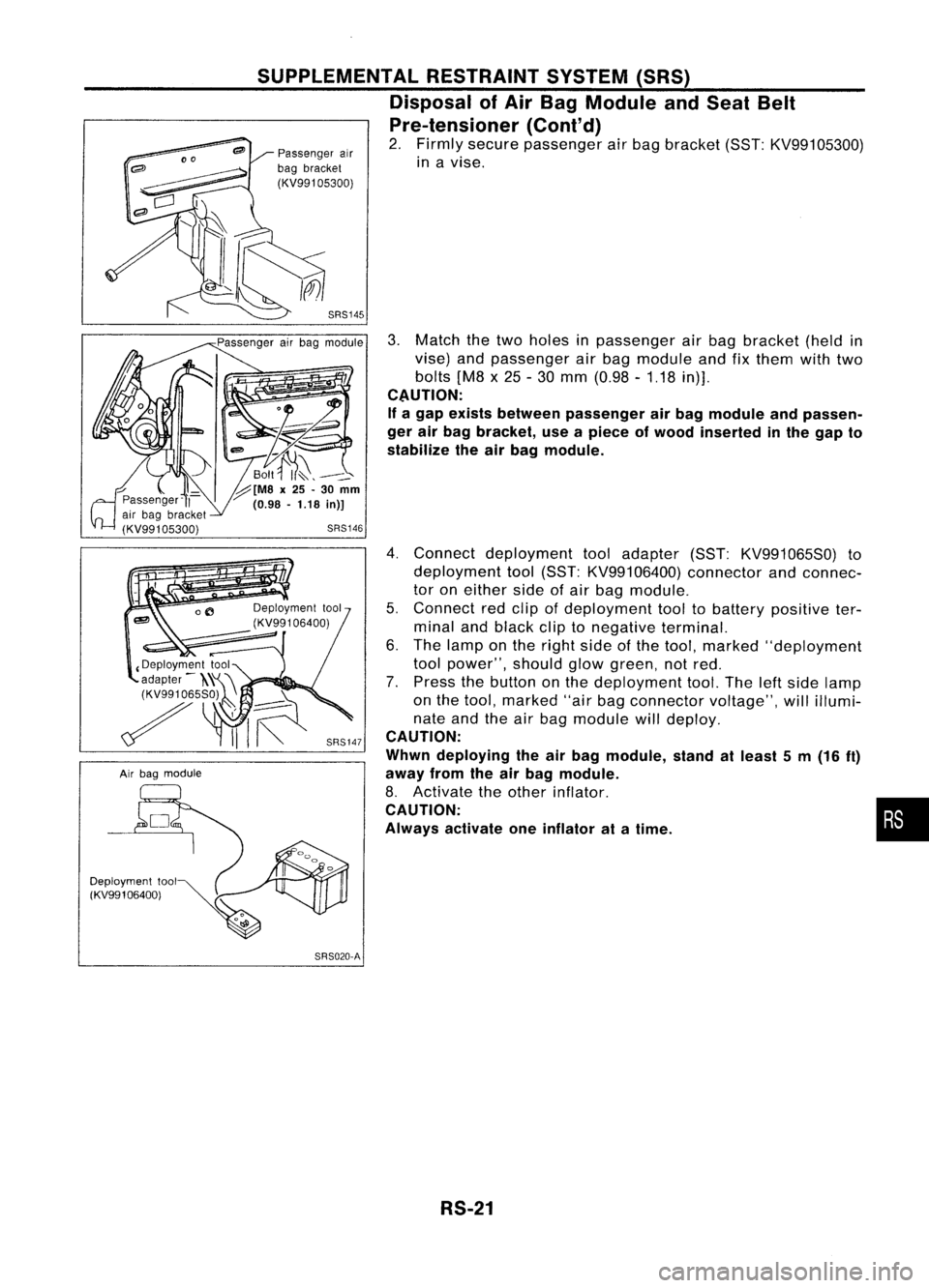
2. Firmly secure passenger airbag bracket (SST:KV99105300)
in avise.
SRS145
3.Match thetwo holes inpassenger airbag bracket (heldin
vise) andpassenger airbag module andfixthem withtwo
bolts [M8x25 -30 mm (0.98 -1.18 in)].
CAUTION:
If a gap exists between passenger airbag module andpassen-
ger airbag bracket, useapiece ofwood inserted inthe gap to
stabilize theairbag module.
4. Connect deployment tooladapter (SST:KV991065S0) to
deployment tool(SST: KV99106400) connectorandconnec-
tor oneither sideofair bag module.
5. Connect redclip ofdeployment tooltobattery positive ter-
minal andblack cliptonegative terminal.
6. The lamp onthe right sideofthe tool, marked "deployment
tool power", shouldglowgreen, notred.
7. Press thebutton onthe deployment tool.Theleftside lamp
on the tool, marked "airbagconnector voltage",willillumi-
nate andtheairbag module willdeploy.
CAUTION:
Whwn deploying theairbag module, standatleast 5m (16
ft)
away fromtheairbag module.
8. Activate theother inflator.
CAUTION:
Always activate oneinflator atatime.
SRS020-A!
RS-21
•
Page 1642 of 1701
SBF240F
SRS006-B
SUPPLEMENTAL
RESTRAINTSYSTEM(SRS)
Disposal ofAir Bag Module andSeat Belt
Pre-tensioner (Cont'd)
DEPLOYMENT OFAIR BAG MODULE WHILEMOUNTED
IN VEHICLE
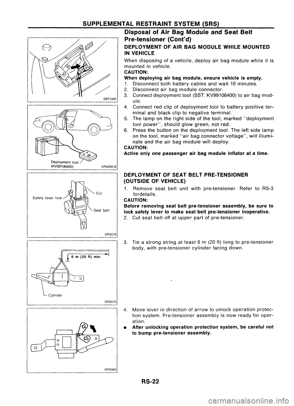
When disposing ofavehicle, deployairbag module whileitis
mounted invehicle.
CAUTION:
When deploying airbag module, ensurevehicle isempty.
1. Disconnect bothbattery cablesandwait 10minutes.
2. Disconnect airbag module connector.
3. Connect deployment tool(SST: KV99106400) toair bag mod-
ule.
4. Connect redclip ofdeployment tooltobattery positive ter-
minal andblack cliptonegative terminal.
5. The lamp onthe right sideofthe tool, marked "deployment
tool power", shouldglowgreen, notred.
6. Press thebutton onthe deployment tool.Theleftside lamp
on the tool, marked "airbagconnector voltage",willillumi-
nate andtheairbag module willdeploy.
CAUTION:
Active onlyonepassenger airbag module inflatoratatime.
Deployment tool
(KV99106400)
Safety leverlock DEPLOYMENT
OFSEAT BELTPRE-TENSIONER
(OUTSIDE OFVEHICLE)
1. Remove seatbeltunitwith pre-tensioner. RefertoRS-3
fordetails.
CAUTION: Before removing seatbeltpre-tensioner assembly,besure to
lock safety levertomake seatbeltpre-tensioner inoperative.
2. Cut seat beltoffatupper partofpre-tensioner.
SRS078
3.Tie astrong stringatleast 6m (20
ft)
long topre-tensioner
body, withpre-tensioner cylinderfacingdown.
SRS079
4.Move leverindirection ofarrow tounlock operation protec-
tion system. Pre-tensioner assemblyisnow ready foroper-
ation.
• After unlocking operationprotection system,becareful not
to bump pre-tensioner assembly.
SRS080 RS-22
Page 1647 of 1701
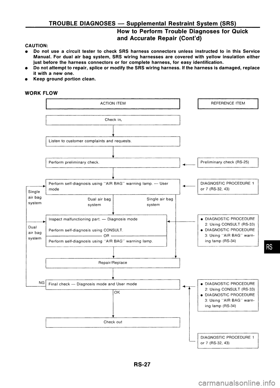
TROUBLEDIAGNOSES -Supplemental RestraintSystem(SRS)
How toPerform TroubleDiagnoses forQuick
and Accurate Repair(Cont'd)
CAUTION:
• Donot use acircuit testertocheck SRSharness connectors unlessinstructed tointhis Service
Manual. Fordual airbag system, SRSwiring harnesses arecovered withyellow insulation either
just before theharness connectors orfor complete harness,foreasy identification.
• Donot attempt torepair, spliceormodify theSRS wiring harness. Ifthe harness isdamaged, replace
it with anew one.
• Keep ground portionclean.
WORK FLOW
ACTIONITEM
Check in.
Listen tocustomer complaints andrequests.
Perform preliminary check. REFERENCE
ITEM
-+-1
Preliminary check(RS-25)
Perform self-diagnosis using"AIRBAG" warning lamp.-User
mode
Single
air bag
system Dual
airbag
system Single
airbag
system DIAGNOSTIC
PROCEDURE1
-+-
or7(RS-32, 43)
Dual
air bag
system Inspect
malfunctioning part.-Diagnosis mode
Perform self-diagnosis usingCONSULT.
OR
Perform self-diagnosis using"AIRBAG" warning lamp.
Repair/Replace •
DIAGNOSTIC PROCEDURE
2: Using CONSULT (RS-33)
• DIAGNOSTIC PROCEDURE
3: Using "AIRBAG" warn-
ing lamp (RS-34)
•
NG Final check -Diagnosis modeandUser mode
OK
Check out
RS-27 •
DIAGNOSTIC PROCEDURE
2: Using CONSULT (RS-33)
• DIAGNOSTIC PROCEDURE
3: Using "AIRBAG" warn-
ing lamp (RS-34)
DIAGNOSTIC PROCEDURE1
or 7(RS-32, 43)
Page 1648 of 1701
TROUBLEDIAGNOSES -Supplemental RestraintSystem(SRS)-
Dual AirBag System
Schematic
FUSE
DUAL
AIRBAG SYSTEM
DATA LINK
CONNECTOR
FOR CONSULT
o
FUSE
COMBINAnON
METER
(AIR BAG
WARNING
LAMP)
19
3
2120
4
5
6
2
15
17
AIR
BAG
DIAGNOSIS
SENSOR UNIT
SPIRAL
CABLE
AIR BAG
MODULE
DRIVER'S
SQUIB SIDE AIR
BAG
MODULE
PASSENGER
SQUIB SIDE
RS-28
-
DOOR SWITCH
DRIVER'S SIDE
HRS002
Page 1649 of 1701
TROUBLEDIAGNOSES -Supplemental RestraintSystem(SRS)-
Dual AirBag System
Wiring Diagram -SRS -
DUAL AIRBAG SYSTEM
RS-SRS-02
IGNITION SWITCH
ON orSTART
::} ToAS-SAS-D.
•
Refer
toEL-POWER.
LHOmode Is
RHOmodels
@:
GAand SRengine
@:
CDengine
@:
Withtachometer
@:
Without tachometer
~f1 ...
@
30
@
40
,
*2
@
9
@
31
*3
@
16
'@
30
,
AIR
BAG
DIAGNOSIS
SENSOR
UNIT
ill)
FUSE
BLOCK
(JIB)
(M15)
10A
1221
IGN
GNO
~ B
~(ll)
C:J~
B
rn~
I
~g~~~CTOR-3
~:
JOINT
CONNECTOR-4
~~:
I
,..O~O-O-ID-
I
<:
R
:>
I~
B B B BB
1
L..t t.J
~ (M60)~
~
(ll)"
*~
BRIW ~ BRIW-.
COMBINATION BRIW
METER ~
(AIR BAG 111511
WARNING WIL
LAMP)
(M30)
~
10A
W
BIR
.....
~
11*.21
BIR
~----------------------------------~
Refertolast page
(Foldout page).
L ~
em
y
(IT)
y
~(M59):
~P
ITIII:illJIIIII
~:
~ BR
HRS004
RS-29
Page 1650 of 1701
TROUBLEDIAGNOSES -Supplemental RestraintSystem(SRS)-
Dual AirBag System
Wiring Diagram -SRS -
{Co nt'd)
RS-SRS-03
AIRBAG
DIAGNOSIS
SENSOR
UNIT
em
AIR BAG
MODULE
PASSENGER
SIDE (SQUIB)
t
SQ-
(PASS)
~
OR
SQ+
(PASS)
~
G
SPIRAL
CABLE
AIR BAG
MODULE
DRIVER'S
SIDE (SQUIB)
t
SQ-
(DR)
~
L
SQ+
(DR)
l!:jJJ
W
DOOR
SWITCH
DRIVER'S
SIDE
@)
OPEN
"=iJ
B
I
f.
B B
~ ~
(B11)
@
DOOR
SW
~
R
~@
ICiJI~
R
I
BOXNO.2
(..JOINT
R CONNECTORS)
I~I ~~: ; ~
R R
I"'m:\
~~
I~IC@
R
<;>
R
0
•
R
m
em
y
@
~cm
y ~ y
Refer
tolast page
(Foldout page).
~~@
5 6lil~1112 W
rfrnl(]ID
l]f
B
~
*6
A,.@
t!!Iy ~y
@
W
HRS005
RS-30