1995 JEEP YJ key
[x] Cancel search: keyPage 1486 of 2158
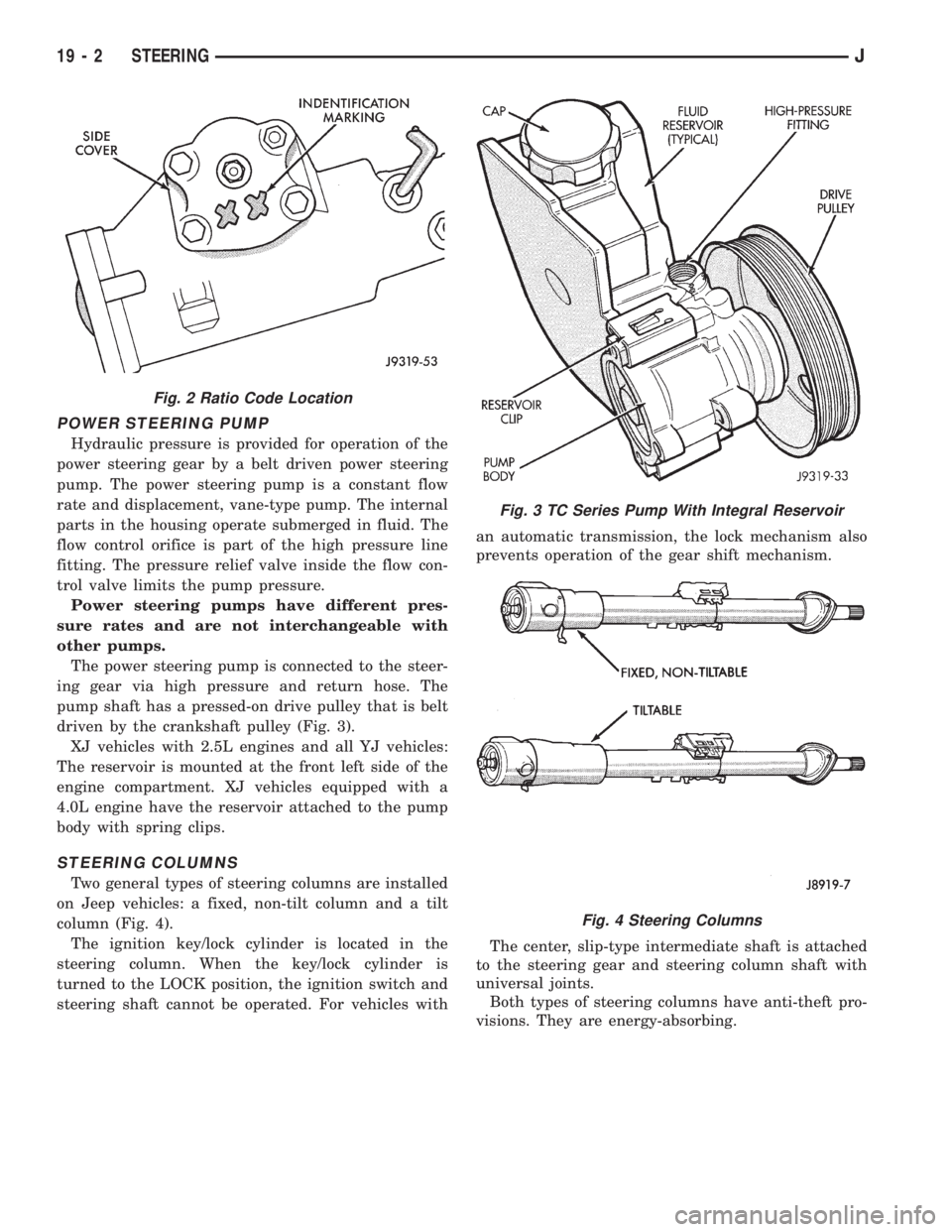
POWER STEERING PUMP
Hydraulic pressure is provided for operation of the
power steering gear by a belt driven power steering
pump. The power steering pump is a constant flow
rate and displacement, vane-type pump. The internal
parts in the housing operate submerged in fluid. The
flow control orifice is part of the high pressure line
fitting. The pressure relief valve inside the flow con-
trol valve limits the pump pressure.
Power steering pumps have different pres-
sure rates and are not interchangeable with
other pumps.
The power steering pump is connected to the steer-
ing gear via high pressure and return hose. The
pump shaft has a pressed-on drive pulley that is belt
driven by the crankshaft pulley (Fig. 3).
XJ vehicles with 2.5L engines and all YJ vehicles:
The reservoir is mounted at the front left side of the
engine compartment. XJ vehicles equipped with a
4.0L engine have the reservoir attached to the pump
body with spring clips.
STEERING COLUMNS
Two general types of steering columns are installed
on Jeep vehicles: a fixed, non-tilt column and a tilt
column (Fig. 4).
The ignition key/lock cylinder is located in the
steering column. When the key/lock cylinder is
turned to the LOCK position, the ignition switch and
steering shaft cannot be operated. For vehicles withan automatic transmission, the lock mechanism also
prevents operation of the gear shift mechanism.
The center, slip-type intermediate shaft is attached
to the steering gear and steering column shaft with
universal joints.
Both types of steering columns have anti-theft pro-
visions. They are energy-absorbing.
Fig. 2 Ratio Code Location
Fig. 3 TC Series Pump With Integral Reservoir
Fig. 4 Steering Columns
19 - 2 STEERINGJ
Page 1537 of 2158
(14) Remove the Interlock cable from the steering
column. Refer to Automatic Transmission Shifter/Ig-
nition Interlock in this group.
(15) Remove the column. Use care to avoid damag-
ing the paint or trim.
INSTALLATION
CAUTION: Bumping, jolting and hammering on the
steering column shaft and gear shift tube must be
avoided during all service procedures.
(1) With the front wheels in the straight ahead po-
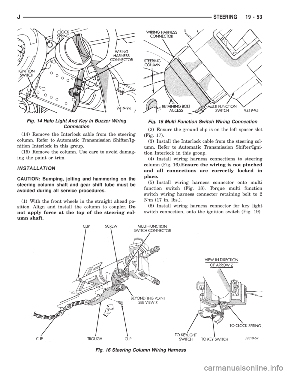
sition. Align and install the column to coupler.Do
not apply force at the top of the steering col-
umn shaft.(2) Ensure the ground clip is on the left spacer slot
(Fig. 17).
(3) Install the Interlock cable from the steering col-
umn. Refer to Automatic Transmission Shifter/Igni-
tion Interlock in this group.
(4) Install wiring harness connections to steering
column (Fig. 16).Ensure the wiring is not pinched
and all connections are correctly locked in
place.
(5) Install wiring harness connector onto multi
function switch (Fig. 18). Torque multi function
switch wiring harness connector retaining bolt to 2
Nzm (17 in. lbs.).
(6) Install wiring harness connector for key light
switch connection, onto the ignition switch (Fig. 19).
Fig. 15 Multi Function Switch Wiring Connection
Fig. 16 Steering Column Wiring Harness
J9519-57
Fig. 14 Halo Light And Key In Buzzer Wiring
Connection
JSTEERING 19 - 53
Page 1538 of 2158
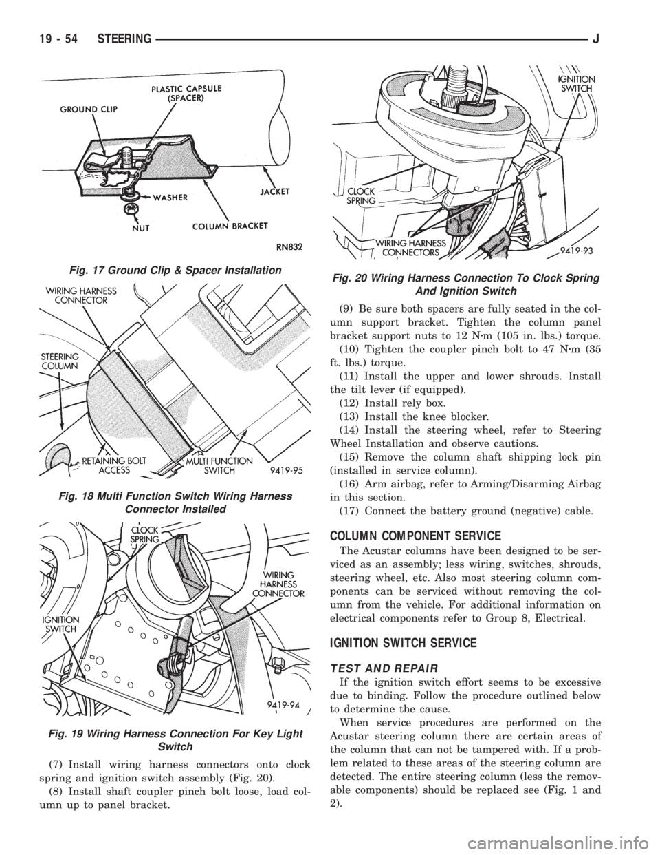
(7) Install wiring harness connectors onto clock
spring and ignition switch assembly (Fig. 20).
(8) Install shaft coupler pinch bolt loose, load col-
umn up to panel bracket.(9) Be sure both spacers are fully seated in the col-
umn support bracket. Tighten the column panel
bracket support nuts to 12 Nzm (105 in. lbs.) torque.
(10) Tighten the coupler pinch bolt to 47 Nzm (35
ft. lbs.) torque.
(11) Install the upper and lower shrouds. Install
the tilt lever (if equipped).
(12) Install rely box.
(13) Install the knee blocker.
(14) Install the steering wheel, refer to Steering
Wheel Installation and observe cautions.
(15) Remove the column shaft shipping lock pin
(installed in service column).
(16) Arm airbag, refer to Arming/Disarming Airbag
in this section.
(17) Connect the battery ground (negative) cable.
COLUMN COMPONENT SERVICE
The Acustar columns have been designed to be ser-
viced as an assembly; less wiring, switches, shrouds,
steering wheel, etc. Also most steering column com-
ponents can be serviced without removing the col-
umn from the vehicle. For additional information on
electrical components refer to Group 8, Electrical.
IGNITION SWITCH SERVICE
TEST AND REPAIR
If the ignition switch effort seems to be excessive
due to binding. Follow the procedure outlined below
to determine the cause.
When service procedures are performed on the
Acustar steering column there are certain areas of
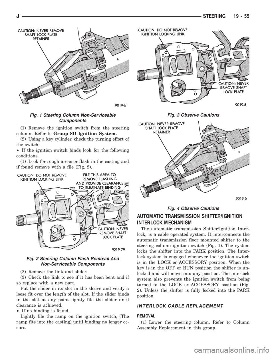
the column that can not be tampered with. If a prob-
lem related to these areas of the steering column are
detected. The entire steering column (less the remov-
able components) should be replaced see (Fig. 1 and
2).
Fig. 17 Ground Clip & Spacer Installation
Fig. 18 Multi Function Switch Wiring Harness
Connector Installed
Fig. 19 Wiring Harness Connection For Key Light
Switch
Fig. 20 Wiring Harness Connection To Clock Spring
And Ignition Switch
19 - 54 STEERINGJ
Page 1539 of 2158
(1) Remove the ignition switch from the steering
column. Refer toGroup 8D Ignition System.
(2) Using a key cylinder, check the turning effort of
the switch.
²If the ignition switch binds look for the following
conditions.
(1) Look for rough areas or flash in the casting and
if found remove with a file (Fig. 2).
(2) Remove the link and slider.
(3) Check the link to see if it has been bent and if
so replace with a new part.
Put the slider in its slot in the sleeve and verify a
loose fit over the length of the slot. If the slider binds
in the slot at any point lightly file the slider until
clearance is achieved.
²If no binding is found.
Lightly file the ramp on the ignition switch, (The
ramp fits into the casting) until binding no longer oc-
curs.
AUTOMATIC TRANSMISSION SHIFTER/IGNITION
INTERLOCK MECHANISM
The automatic transmission Shifter/Ignition Inter-
lock, is a cable operated system. It interconnects the
automatic transmission floor mounted shifter to the
steering column ignition switch (Fig. 1). The system
locks the shifter into the PARK position. The Inter-
lock system is engaged whenever the ignition switch
is in the LOCK or ACCESSORY position. When the
key is in the OFF or RUN position the shifter is un-
locked and will move into any position. The interlock
system also prevents the ignition switch from being
turned to the LOCK or ACCESSORY position (Fig.
2). Unless the shifter is fully locked into the PARK
position.
INTERLOCK CABLE REPLACEMENT
REMOVAL
(1) Lower the steering column. Refer to Column
Assembly Replacement in this group.
Fig. 1 Steering Column Non-Serviceable
Components
Fig. 2 Steering Column Flash Removal And
Non-Serviceable Components
Fig. 3 Observe Cautions
Fig. 4 Observe Cautions
JSTEERING 19 - 55
Page 1540 of 2158
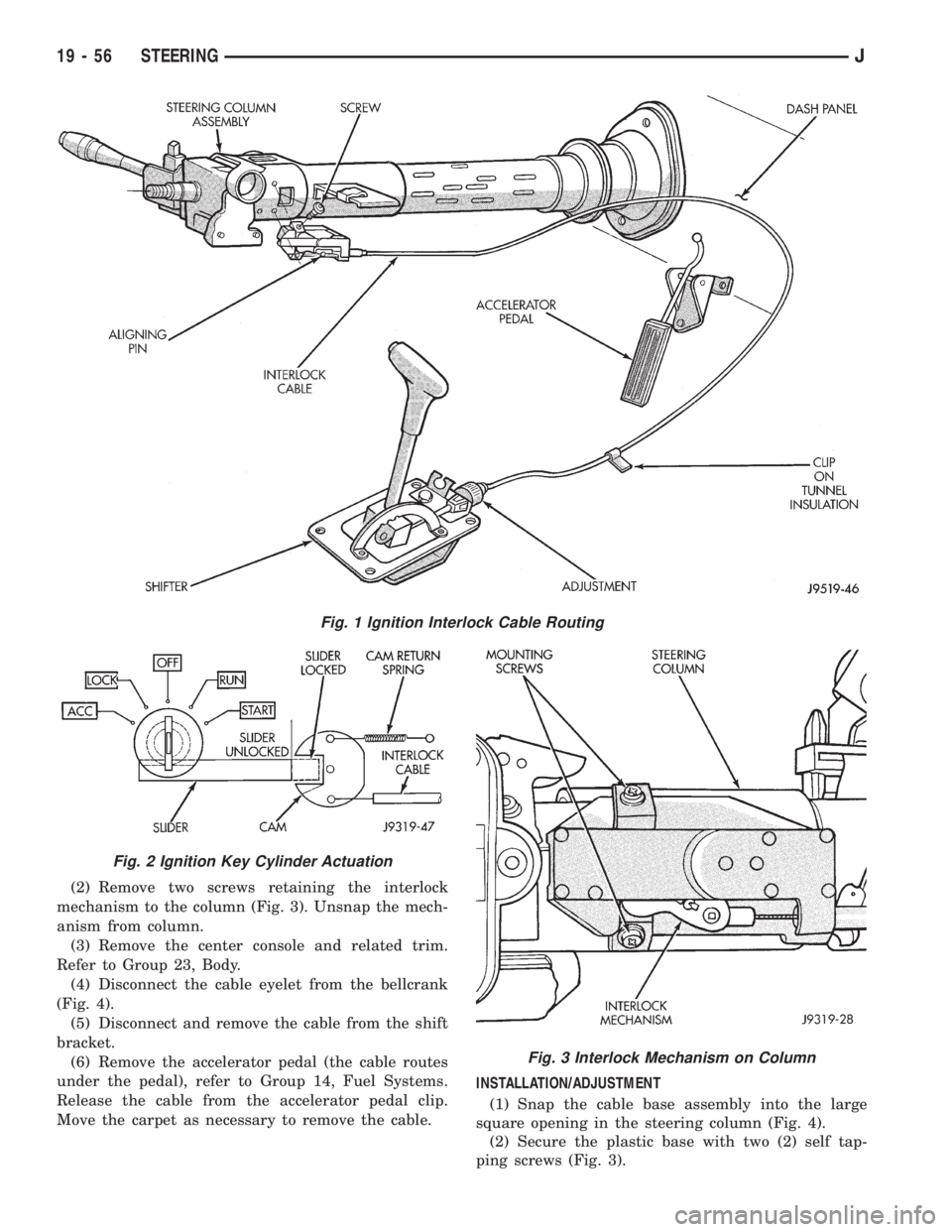
(2) Remove two screws retaining the interlock
mechanism to the column (Fig. 3). Unsnap the mech-
anism from column.
(3) Remove the center console and related trim.
Refer to Group 23, Body.
(4) Disconnect the cable eyelet from the bellcrank
(Fig. 4).
(5) Disconnect and remove the cable from the shift
bracket.
(6) Remove the accelerator pedal (the cable routes
under the pedal), refer to Group 14, Fuel Systems.
Release the cable from the accelerator pedal clip.
Move the carpet as necessary to remove the cable.INSTALLATION/ADJUSTMENT
(1) Snap the cable base assembly into the large
square opening in the steering column (Fig. 4).
(2) Secure the plastic base with two (2) self tap-
ping screws (Fig. 3).
Fig. 1 Ignition Interlock Cable Routing
Fig. 2 Ignition Key Cylinder Actuation
Fig. 3 Interlock Mechanism on Column
19 - 56 STEERINGJ
Page 1541 of 2158
(3) Place the ignition key cylinder in the ACCES-
SORY position.
(4) Remove shipping pin from plastic base.
(5) Connect the cable eyelet to the bellcrank pin
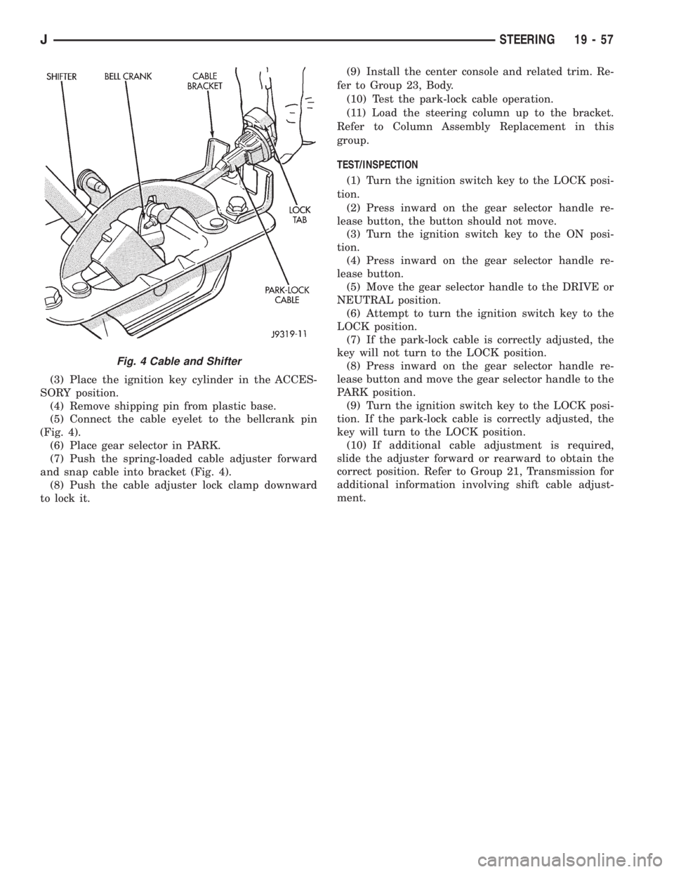
(Fig. 4).
(6) Place gear selector in PARK.
(7) Push the spring-loaded cable adjuster forward
and snap cable into bracket (Fig. 4).
(8) Push the cable adjuster lock clamp downward
to lock it.(9) Install the center console and related trim. Re-
fer to Group 23, Body.
(10) Test the park-lock cable operation.
(11) Load the steering column up to the bracket.
Refer to Column Assembly Replacement in this
group.
TEST/INSPECTION
(1) Turn the ignition switch key to the LOCK posi-
tion.
(2) Press inward on the gear selector handle re-
lease button, the button should not move.
(3) Turn the ignition switch key to the ON posi-
tion.
(4) Press inward on the gear selector handle re-
lease button.
(5) Move the gear selector handle to the DRIVE or
NEUTRAL position.
(6) Attempt to turn the ignition switch key to the
LOCK position.
(7) If the park-lock cable is correctly adjusted, the
key will not turn to the LOCK position.
(8) Press inward on the gear selector handle re-
lease button and move the gear selector handle to the
PARK position.
(9) Turn the ignition switch key to the LOCK posi-
tion. If the park-lock cable is correctly adjusted, the
key will turn to the LOCK position.
(10) If additional cable adjustment is required,
slide the adjuster forward or rearward to obtain the
correct position. Refer to Group 21, Transmission for
additional information involving shift cable adjust-
ment.
Fig. 4 Cable and Shifter
JSTEERING 19 - 57
Page 1544 of 2158
(6) Column shift vehicles, install the shift cable
grommet on the shift lever.
(7) Install and tighten the toe plate to floor pan
bolts/nuts to 21.5 Nzm (192 in. lbs.) torque (Fig. 5).
(8) Install the lower portion of the instrument
panel, refer to Group 8E, Instrument Panel.
(9) Install steering wheel on column, refer to Steer-
ing Wheel-Installation.
(10) Connect the negative (ground) cable to the
battery.
NON-TILT STEERING COLUMN
DISASSEMBLYÐCOLUMN OR CONSOLE SHIFT
Steering column removal from the vehicle is not
necessary for;
²Lockplate cover
²Lockplate
²Steering shaft retaining ring
²Canceling cam
²Turn signal switch
²Upper bearing preload spring
²Ignition key/lock cylinder service
The steering column must be removed from
the vehicle to service any other component.
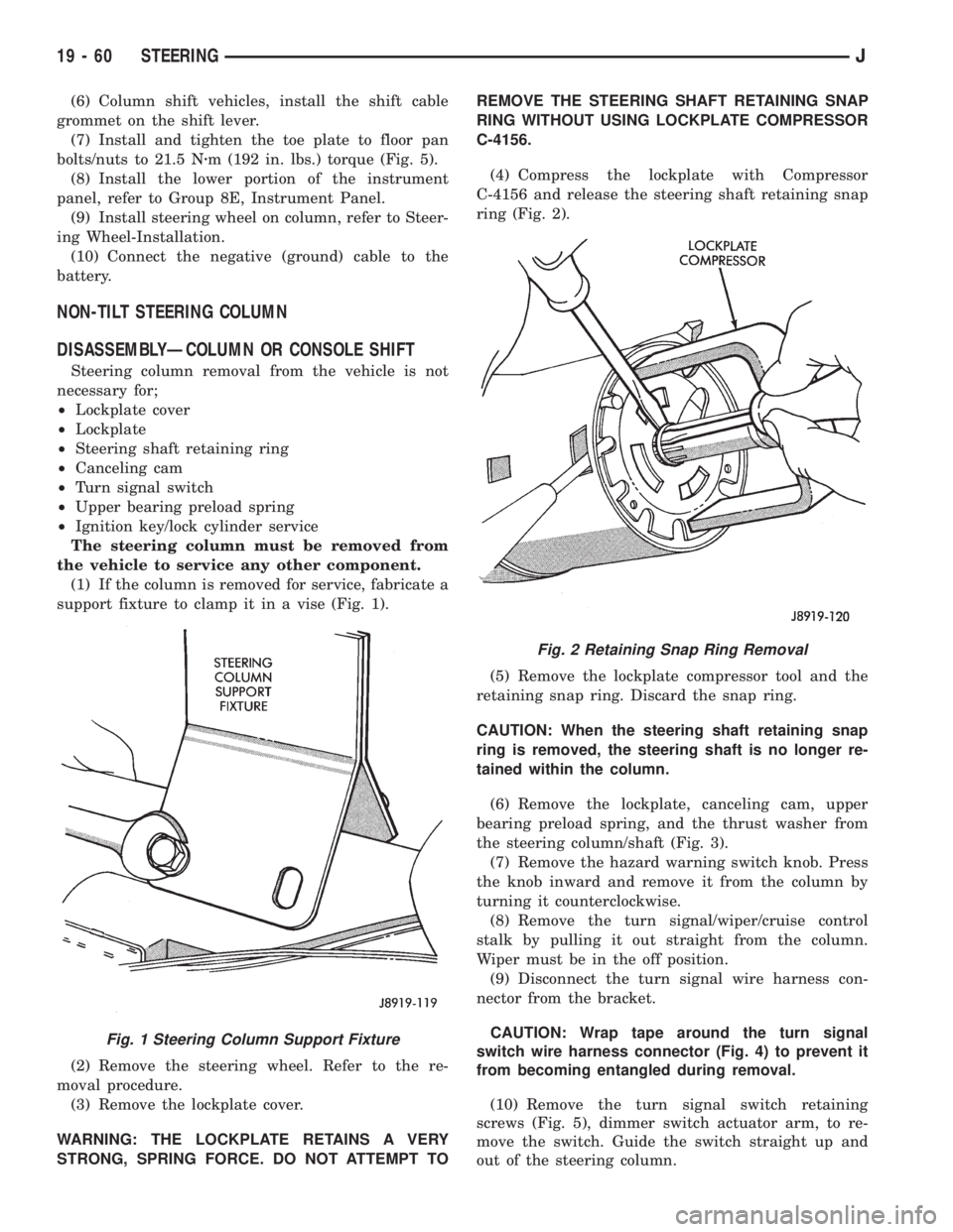
(1) If the column is removed for service, fabricate a
support fixture to clamp it in a vise (Fig. 1).
(2) Remove the steering wheel. Refer to the re-
moval procedure.
(3) Remove the lockplate cover.
WARNING: THE LOCKPLATE RETAINS A VERY
STRONG, SPRING FORCE. DO NOT ATTEMPT TOREMOVE THE STEERING SHAFT RETAINING SNAP
RING WITHOUT USING LOCKPLATE COMPRESSOR
C-4156.
(4) Compress the lockplate with Compressor
C-4156 and release the steering shaft retaining snap
ring (Fig. 2).
(5) Remove the lockplate compressor tool and the
retaining snap ring. Discard the snap ring.
CAUTION: When the steering shaft retaining snap
ring is removed, the steering shaft is no longer re-
tained within the column.
(6) Remove the lockplate, canceling cam, upper
bearing preload spring, and the thrust washer from
the steering column/shaft (Fig. 3).
(7) Remove the hazard warning switch knob. Press
the knob inward and remove it from the column by
turning it counterclockwise.
(8) Remove the turn signal/wiper/cruise control
stalk by pulling it out straight from the column.
Wiper must be in the off position.
(9) Disconnect the turn signal wire harness con-
nector from the bracket.
CAUTION: Wrap tape around the turn signal
switch wire harness connector (Fig. 4) to prevent it
from becoming entangled during removal.
(10) Remove the turn signal switch retaining
screws (Fig. 5), dimmer switch actuator arm, to re-
move the switch. Guide the switch straight up and
out of the steering column.
Fig. 1 Steering Column Support Fixture
Fig. 2 Retaining Snap Ring Removal
19 - 60 STEERINGJ
Page 1545 of 2158
(11) Remove the wiper switch wire harness and all
the other wire harnesses located within the steering
column.
(12) Insert the ignition switch key into the key/lock
cylinder and turn to the ON position.
CAUTION: Do not attempt to remove the key warn-
ing buzzer switch and contacts separately. If sepa-
rated, the contacts can detach and drop into the
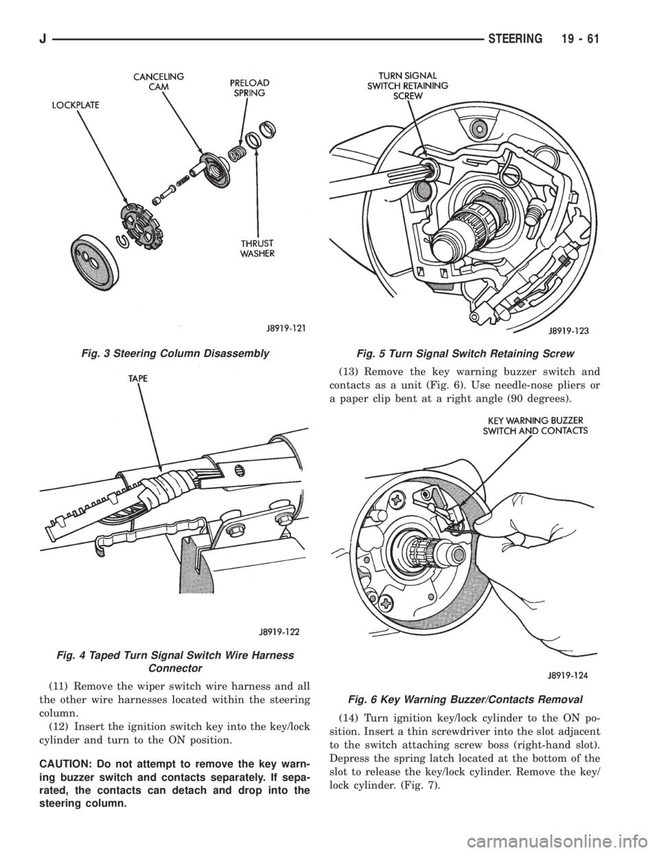
steering column.(13) Remove the key warning buzzer switch and
contacts as a unit (Fig. 6). Use needle-nose pliers or
a paper clip bent at a right angle (90 degrees).
(14) Turn ignition key/lock cylinder to the ON po-
sition. Insert a thin screwdriver into the slot adjacent
to the switch attaching screw boss (right-hand slot).
Depress the spring latch located at the bottom of the
slot to release the key/lock cylinder. Remove the key/
lock cylinder. (Fig. 7).
Fig. 3 Steering Column Disassembly
Fig. 4 Taped Turn Signal Switch Wire Harness
Connector
Fig. 5 Turn Signal Switch Retaining Screw
Fig. 6 Key Warning Buzzer/Contacts Removal
JSTEERING 19 - 61