1995 JEEP YJ key
[x] Cancel search: keyPage 1965 of 2158
(3) Remove the window weatherstrip seals from
the door.
(4) Remove the trim panel and waterdam from
door inner panel.
(5) Remove the channel/division bar screws. Drill
out the rivet head to remove it from the inner panel.
(6) Tilt the channel/division bar forward and re-
move it from the door.
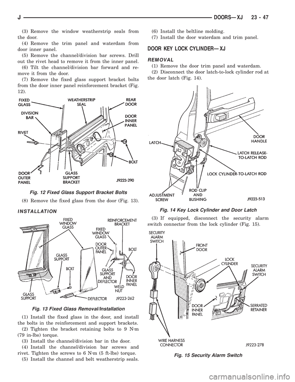
(7) Remove the fixed glass support bracket bolts
from the door inner panel reinforcement bracket (Fig.
12).
(8) Remove the fixed glass from the door (Fig. 13).
INSTALLATION
(1) Install the fixed glass in the door, and install
the bolts in the reinforcement and support brackets.
(2) Tighten the bracket retaining bolts to 9 Nzm
(79 in-lbs) torque.
(3) Install the channel/division bar in the door.
(4) Install the channel/division bar screws and
rivet. Tighten the screws to 6 Nzm (5 ft-lbs) torque.
(5) Install the channel and belt weatherstrip seals.(6) Install the beltline molding.
(7) Install the door waterdam and trim panel.
DOOR KEY LOCK CYLINDERÐXJ
REMOVAL
(1) Remove the door trim panel and waterdam.
(2) Disconnect the door latch-to-lock cylinder rod at
the door latch (Fig. 14).
(3) If equipped, disconnect the security alarm
switch connector from the lock cylinder (Fig. 15).
Fig. 12 Fixed Glass Support Bracket Bolts
Fig. 13 Fixed Glass Removal/Installation
Fig. 14 Key Lock Cylinder and Door Latch
Fig. 15 Security Alarm Switch
JDOORSÐXJ 23 - 47
Page 1966 of 2158
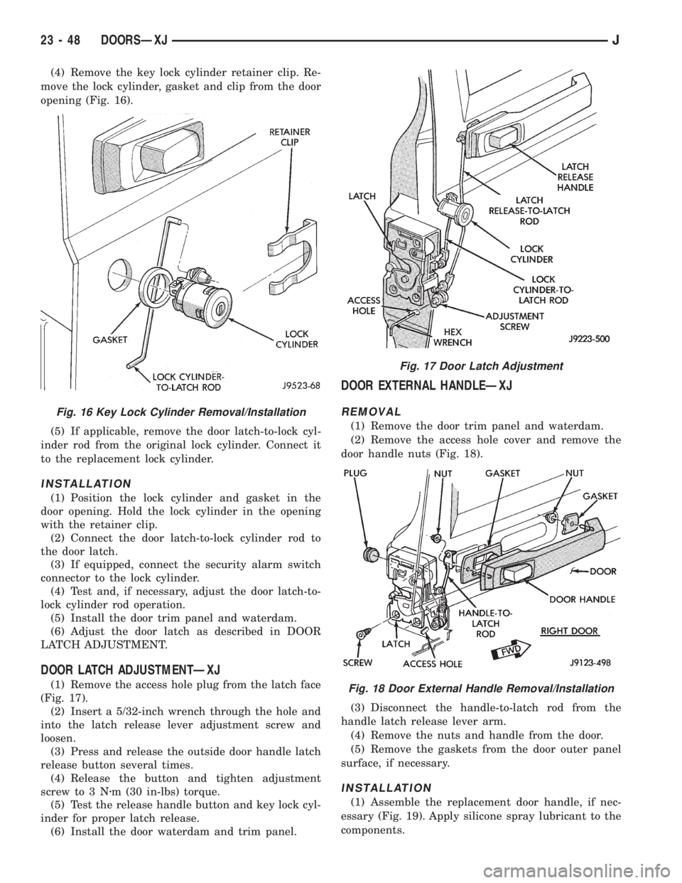
(4) Remove the key lock cylinder retainer clip. Re-
move the lock cylinder, gasket and clip from the door
opening (Fig. 16).
(5) If applicable, remove the door latch-to-lock cyl-
inder rod from the original lock cylinder. Connect it
to the replacement lock cylinder.
INSTALLATION
(1) Position the lock cylinder and gasket in the
door opening. Hold the lock cylinder in the opening
with the retainer clip.
(2) Connect the door latch-to-lock cylinder rod to
the door latch.
(3) If equipped, connect the security alarm switch
connector to the lock cylinder.
(4) Test and, if necessary, adjust the door latch-to-
lock cylinder rod operation.
(5) Install the door trim panel and waterdam.
(6) Adjust the door latch as described in DOOR
LATCH ADJUSTMENT.
DOOR LATCH ADJUSTMENTÐXJ
(1) Remove the access hole plug from the latch face
(Fig. 17).
(2) Insert a 5/32-inch wrench through the hole and
into the latch release lever adjustment screw and
loosen.
(3) Press and release the outside door handle latch
release button several times.
(4) Release the button and tighten adjustment
screw to 3 Nzm (30 in-lbs) torque.
(5) Test the release handle button and key lock cyl-
inder for proper latch release.
(6) Install the door waterdam and trim panel.
DOOR EXTERNAL HANDLEÐXJ
REMOVAL
(1) Remove the door trim panel and waterdam.
(2) Remove the access hole cover and remove the
door handle nuts (Fig. 18).
(3) Disconnect the handle-to-latch rod from the
handle latch release lever arm.
(4) Remove the nuts and handle from the door.
(5) Remove the gaskets from the door outer panel
surface, if necessary.
INSTALLATION
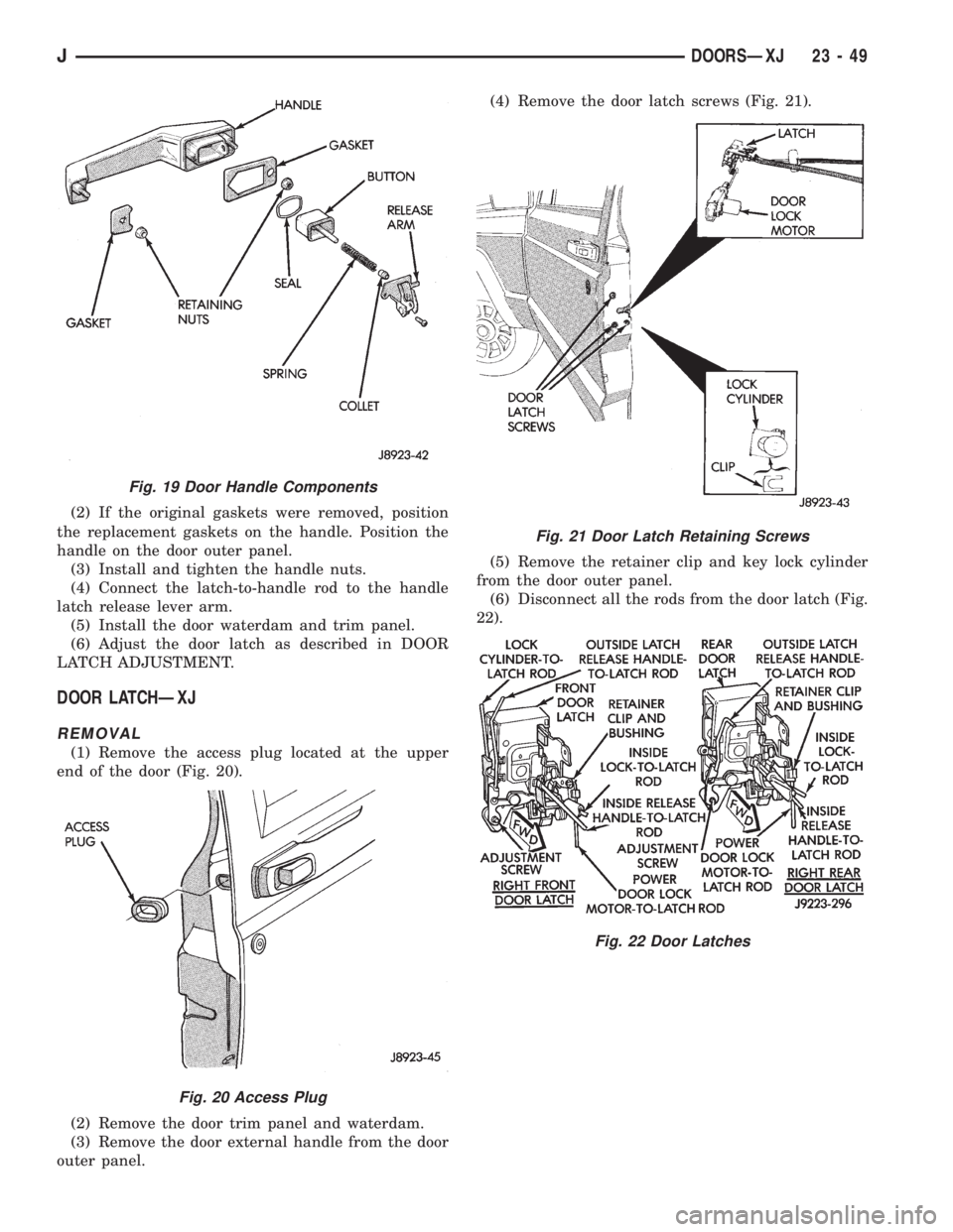
(1) Assemble the replacement door handle, if nec-
essary (Fig. 19). Apply silicone spray lubricant to the
components.
Fig. 16 Key Lock Cylinder Removal/Installation
Fig. 17 Door Latch Adjustment
Fig. 18 Door External Handle Removal/Installation
23 - 48 DOORSÐXJJ
Page 1967 of 2158
(2) If the original gaskets were removed, position
the replacement gaskets on the handle. Position the
handle on the door outer panel.
(3) Install and tighten the handle nuts.
(4) Connect the latch-to-handle rod to the handle
latch release lever arm.
(5) Install the door waterdam and trim panel.
(6) Adjust the door latch as described in DOOR
LATCH ADJUSTMENT.
DOOR LATCHÐXJ
REMOVAL
(1) Remove the access plug located at the upper
end of the door (Fig. 20).
(2) Remove the door trim panel and waterdam.
(3) Remove the door external handle from the door
outer panel.(4) Remove the door latch screws (Fig. 21).
(5) Remove the retainer clip and key lock cylinder
from the door outer panel.
(6) Disconnect all the rods from the door latch (Fig.
22).
Fig. 19 Door Handle Components
Fig. 20 Access Plug
Fig. 21 Door Latch Retaining Screws
Fig. 22 Door Latches
JDOORSÐXJ 23 - 49
Page 1968 of 2158
(7) Remove the door latch from the door face.
(8) For vehicles equipped with power door locks,
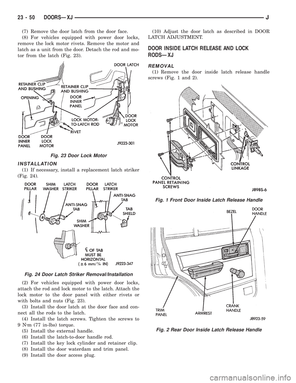
remove the lock motor rivets. Remove the motor and
latch as a unit from the door. Detach the rod and mo-
tor from the latch (Fig. 23).
INSTALLATION
(1) If necessary, install a replacement latch striker
(Fig. 24).
(2) For vehicles equipped with power door locks,
attach the rod and lock motor to the latch. Attach the
lock motor to the door panel with either rivets or
with bolts and nuts (Fig. 23).
(3) Install the door latch at the door face and con-
nect all the rods to the latch.
(4) Install the latch screws. Tighten the screws to
9Nzm (77 in-lbs) torque.
(5) Install the external handle.
(6) Install the latch-to-door handle rod.
(7) Install the key lock cylinder and retainer clip.
(8) Install the door waterdam and trim panel.
(9) Install the door access plug.(10) Adjust the door latch as described in DOOR
LATCH ADJUSTMENT.
DOOR INSIDE LATCH RELEASE AND LOCK
RODSÐXJ
REMOVAL
(1) Remove the door inside latch release handle
screws (Fig. 1 and 2).
Fig. 23 Door Lock Motor
Fig. 24 Door Latch Striker Removal/Installation
Fig. 1 Front Door Inside Latch Release Handle
Fig. 2 Rear Door Inside Latch Release Handle
23 - 50 DOORSÐXJJ
Page 1979 of 2158
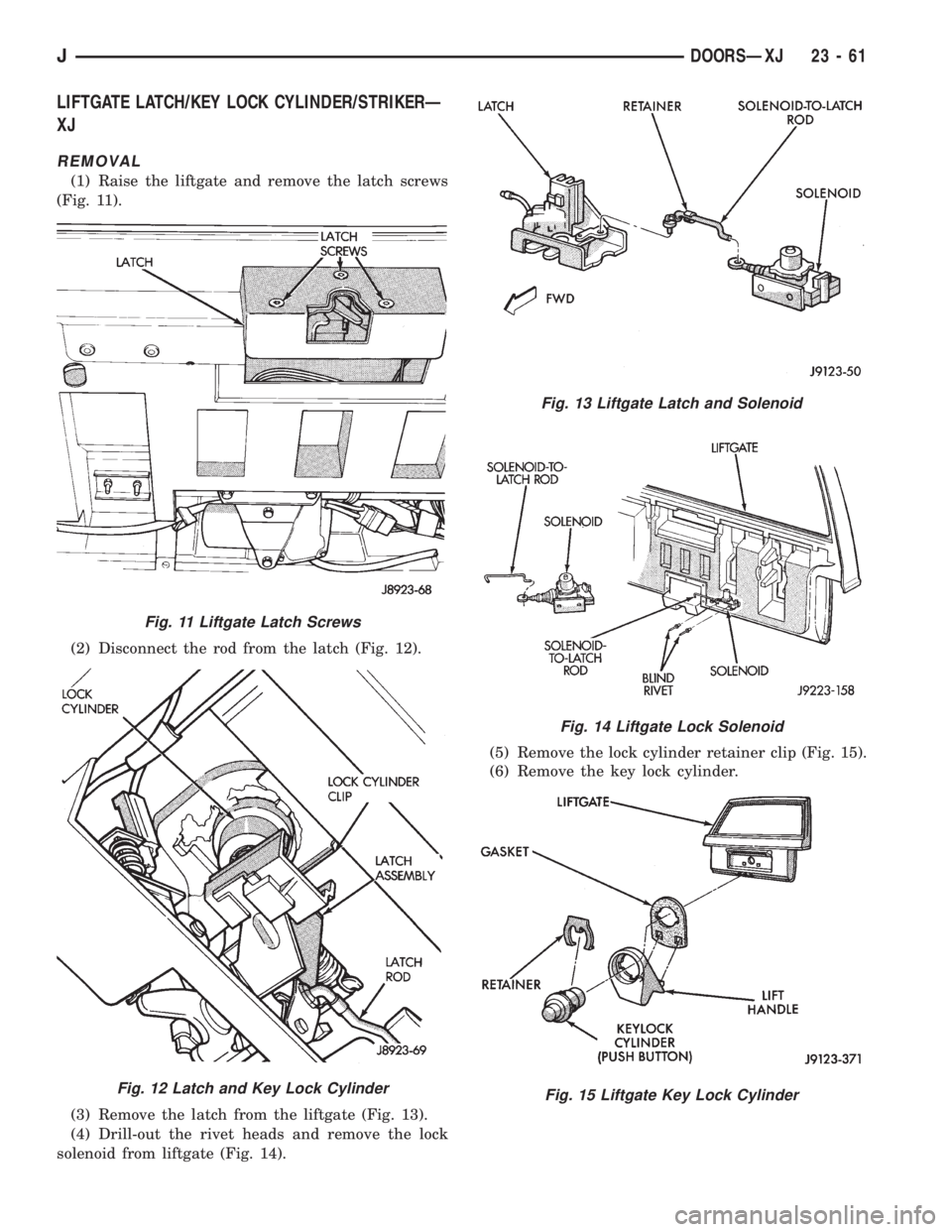
LIFTGATE LATCH/KEY LOCK CYLINDER/STRIKERÐ
XJ
REMOVAL
(1) Raise the liftgate and remove the latch screws
(Fig. 11).
(2) Disconnect the rod from the latch (Fig. 12).
(3) Remove the latch from the liftgate (Fig. 13).
(4) Drill-out the rivet heads and remove the lock
solenoid from liftgate (Fig. 14).(5) Remove the lock cylinder retainer clip (Fig. 15).
(6) Remove the key lock cylinder.
Fig. 11 Liftgate Latch Screws
Fig. 12 Latch and Key Lock Cylinder
Fig. 13 Liftgate Latch and Solenoid
Fig. 14 Liftgate Lock Solenoid
Fig. 15 Liftgate Key Lock Cylinder
JDOORSÐXJ 23 - 61
Page 1980 of 2158
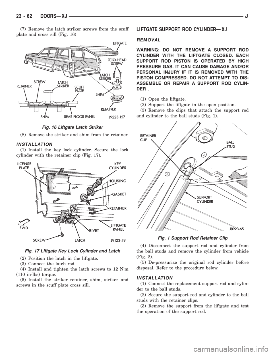
(7) Remove the latch striker screws from the scuff
plate and cross sill (Fig. 16)
(8) Remove the striker and shim from the retainer.
INSTALLATION
(1) Install the key lock cylinder. Secure the lock
cylinder with the retainer clip (Fig. 17).
(2) Position the latch in the liftgate.
(3) Connect the latch rod.
(4) Install and tighten the latch screws to 12 Nzm
(110 in-lbs) torque.
(5) Install the striker retainer, shim, striker and
screws in the scuff plate cross sill.
LIFTGATE SUPPORT ROD CYLINDERÐXJ
REMOVAL
WARNING: DO NOT REMOVE A SUPPORT ROD
CYLINDER WITH THE LIFTGATE CLOSED. EACH
SUPPORT ROD PISTON IS OPERATED BY HIGH
PRESSURE GAS. IT CAN CAUSE DAMAGE AND/OR
PERSONAL INJURY IF IT IS REMOVED WITH THE
PISTON COMPRESSED. DO NOT ATTEMPT TO DIS-
ASSEMBLE OR REPAIR A SUPPORT ROD CYLIN-
DER.
(1) Open the liftgate.
(2) Support the liftgate in the open position.
(3) Remove the clips that attach the support rod
and cylinder to the ball studs (Fig. 1).
(4) Disconnect the support rod and cylinder from
the ball studs and remove the cylinder from vehicle
(Fig. 2).
(5) De-pressurize the original rod cylinder before
disposal. Refer to the procedure below.
INSTALLATION
(1) Connect the replacement support rod and cylin-
der to the ball studs.
(2) Secure the support rod and cylinder to the ball
studs with the retainer clips.
(3) Remove the support from the liftgate and test
the operation of the support rod.
Fig. 16 Liftgate Latch Striker
Fig. 17 Liftgate Key Lock Cylinder and Latch
Fig. 1 Support Rod Retainer Clip
23 - 62 DOORSÐXJJ
Page 1998 of 2158
INTERIOR COMPONENTS
INDEX
page page
Assist HandleÐXJ........................ 89
B/C-Pillar and Liftgate Pillar Trim CoversÐXJ.... 88
Bucket Seat Cushion and CoverÐXJ........... 81
Bucket Seat PlatformÐXJ................... 82
Bucket Seatback Cover and FrameÐXJ........ 81
Cargo BarrierÐXJ........................ 101
Cargo LampÐXJ......................... 94
Carpets and Floor MatsÐXJ................. 99
Dome LampÐXJ......................... 93
Front Bucket SeatsÐXJ.................... 81
Front Carpet/MatÐXJ...................... 99
Front Inner Scuff Plate/Cowl Side Trim PanelÐXJ . 86
Front Shoulder Belt/BuckleÐXJ............... 90
Full Floor ConsoleÐXJ..................... 95
HeadlinerÐXJ............................ 92
I/P Ash Receiver Tray LampÐXJ.............. 80
Instrument Cluster BezelÐXJ................ 80
Interior Trim Panels and Scuff PlatesÐXJ....... 84
Jack StorageÐXJ......................... 97
Keyless Entry ReceiverÐXJ................. 93Mini-Console with Floor ShiftÐXJ............. 94
Mini-Floor ConsoleÐXJ..................... 94
Outer Scuff PlatesÐXJ..................... 89
Overhead ConsoleÐXJ..................... 93
Parking Brake Handle CoverÐXJ............. 94
Quarter and Wheelhouse Trim PanelsÐXJ...... 87
Quarter Trim Panel ExtensionÐXJ............. 87
Rear Carpet/MatÐXJ..................... 100
Rear Seat Cushion CoverÐXJ............... 82
Rear Seat CushionÐXJ.................... 82
Rear Seatback CoverÐXJ................... 84
Rear Seatback Latch Striker and BumperÐXJ.... 84
Rear SeatbackÐXJ........................ 83
Rear Shoulder/Lap Belt/BuckleÐXJ............ 91
Sound BarÐXJ........................... 94
Spare Tire/Wheel Holddown and Floor
BracketsÐXJ........................... 98
SunvisorsÐXJ........................... 93
Windshield Side MoldingÐXJ................ 86
INSTRUMENT CLUSTER BEZELÐXJ
REMOVAL
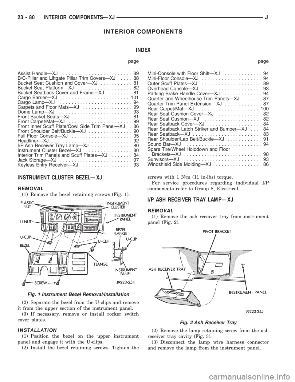
(1) Remove the bezel retaining screws (Fig. 1).
(2) Separate the bezel from the U-clips and remove
it from the upper section of the instrument panel.
(3) If necessary, remove or install rocker switch
cover plates.
INSTALLATION
(1) Position the bezel on the upper instrument
panel and engage it with the U-clips.
(2) Install the bezel retaining screws. Tighten thescrews with 1 Nzm (11 in-lbs) torque.
For service procedures regarding individual I/P
components refer to Group 8, Electrical.
I/P ASH RECEIVER TRAY LAMPÐXJ
REMOVAL
(1) Remove the ash receiver tray from instrument
panel (Fig. 2).
(2) Remove the lamp retaining screw from the ash
receiver tray cavity (Fig. 3).
(3) Disconnect the lamp wire harness connector
and remove the lamp from the instrument panel.
Fig. 1 Instrument Bezel Removal/Installation
Fig. 2 Ash Receiver Tray
23 - 80 INTERIOR COMPONENTSÐXJJ
Page 2010 of 2158
INSPECTION
Inspect the rear shoulder/lap belts and buckles. Re-
place any belt that is either cut, frayed, torn or dam-
aged in any way. Replace the shoulder belt if the
retractor is damaged or inoperative.
INSTALLATION
(1) Position the shoulder belt buckle and the lap
belt/buckle anchor plates on the floor panel.
(2) Install the anchor bolts. Tighten the bolts to 37
Nzm (27 ft-lbs) torque.
(3) Position the shoulder belt at the roof rail and
install the upper anchor bolt. Tighten the bolt to 37
Nzm (27 ft-lbs) torque.
(4) Route the shoulder belt through the quarter
trim panel slot. Install the retractor support on the
rear quarter rail. Tighten the screw to 5 Nzm (45 in-
lbs) torque.
(5) Install the quarter trim panel.
(6) Install the shoulder belt lower anchor bolt.
Tighten the bolt to 37 Nzm (27 ft-lbs) torque.
(7) Return the rear seat to the normal position and
engage the latch.
HEADLINERÐXJ
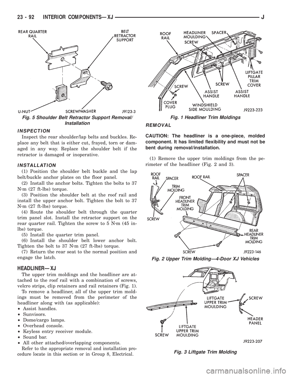
The upper trim moldings and the headliner are at-
tached to the roof rail with a combination of screws,
velcro strips, clip retainers and rail retainers (Fig. 1).
To remove a headliner, all of the upper trim mold-
ings must be removed from the perimeter of the
headliner along with (as applicable):
²Assist handles.
²Sunvisors.
²Dome/cargo lamps.
²Overhead console.
²Keyless entry receiver module.
²Sound bar.
²All other attached/overlapping components.
Refer to the appropriate removal and installation pro-
cedure locate in this section or in Group 8, Electrical.
REMOVAL
CAUTION: The headliner is a one-piece, molded
component. It has limited flexibility and must not be
bent during removal/installation.
(1) Remove the upper trim moldings from the pe-
rimeter of the headliner (Fig. 2 and 3).
Fig. 5 Shoulder Belt Retractor Support Removal/
InstallationFig. 1 Headliner Trim Moldings
Fig. 2 Upper Trim MoldingÐ4-Door XJ Vehicles
Fig. 3 Liftgate Trim Molding
23 - 92 INTERIOR COMPONENTSÐXJJ