1995 JEEP YJ key
[x] Cancel search: keyPage 2011 of 2158
(2) Ensure that all the retainer clips, screws and
Velcro strips are disengaged before removing the
headliner.
HEADLINER INSTALLATION
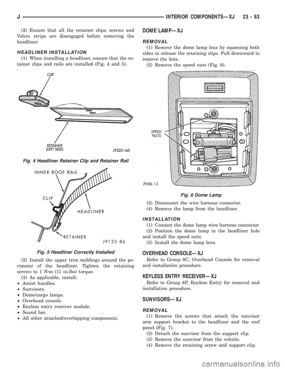
(1) When installing a headliner, ensure that the re-
tainer clips and rails are installed (Fig. 4 and 5).
(2) Install the upper trim moldings around the pe-
rimeter of the headliner. Tighten the retaining
screws to 1 Nzm (11 in-lbs) torque.
(3) As applicable, install:
²Assist handles.
²Sunvisors.
²Dome/cargo lamps.
²Overhead console.
²Keyless entry receiver module.
²Sound bar.
²All other attached/overlapping components.
DOME LAMPÐXJ
REMOVAL
(1) Remove the dome lamp lens by squeezing both
sides to release the retaining clips. Pull downward to
remove the lens.
(2) Remove the speed nuts (Fig. 6).
(3) Disconnect the wire harness connector.
(4) Remove the lamp from the headliner.
INSTALLATION
(1) Connect the dome lamp wire harness connector.
(2) Position the dome lamp in the headliner hole
and install the speed nuts.
(3) Install the dome lamp lens.
OVERHEAD CONSOLEÐXJ
Refer to Group 8C, Overhead Console for removal
and installation procedure.
KEYLESS ENTRY RECEIVERÐXJ
Refer to Group 8P, Keyless Entry for removal and
installation procedure.
SUNVISORSÐXJ
REMOVAL
(1) Remove the screws that attach the sunvisor
arm support bracket to the headliner and the roof
panel (Fig. 7).
(2) Detach the sunvisor from the support clip.
(3) Remove the sunvisor from the vehicle.
(4) Remove the retaining screw and support clip.
Fig. 4 Headliner Retainer Clip and Retainer Rail
Fig. 5 Headliner Correctly Installed
Fig. 6 Dome Lamp
JINTERIOR COMPONENTSÐXJ 23 - 93
Page 2035 of 2158
The work area temperature should be between
18ÉC (65ÉF) and 32ÉC (90ÉF).A tape stripe/decal
should not be replaced if the work area temper-
ature is less than 18ÉC (65ÉF).
The following equipment and material are neces-
sary for body stripe/decal removal and installation:
²Commercial tape stripe/decal removal solution.
²Commercial adhesive removal solution.
²Liquid dish detergent (for the wetting solution).
²Mixture of wetting solution.
²Commercial wax and silicone removal solution.
²Isopropyl (rubbing) alcohol.
²Small squeegee (plastic or hard rubber).
²Water bucket and sponge.
²Clean wiping rags or paper towels.
²Heat gun (or infra-red heat bulb).
²Wax pencil.
²Sharp knife, single edge razor blade or X-acto
knife.
²Pair of scissors.
²Needle or pin.
A wetting solution assures a better bond between
the painted surface of the body and the tape stripe/
decal. Prepare a supply of wetting solution by mixing
two or three teaspoons of dish detergent with 1 gal-
lon of water.Do not use soap.
Too much detergent will reduce the effective-
ness of the mixture.
REMOVAL
The key to successful tape stripe/decal re-
moval is to apply heat to area and slowly peel
stripe/decal from panel.
(1) Clean the repaired surface, adjacent panels and
door openings as necessary.
(2) Start at one end of the tape stripe/decal and
apply heat with a heat gun. Slowly peel the stripe/
decal from the panel by pulling it back.Do not pull
the tape stripe/decal outward from the panel.
WARNING: USE THE TAPE STRIPE/DECAL RE-
MOVAL SOLUTION IN A WELL-VENTILATED AREA
ONLY.
(3) A commercial tape stripe/decal removal solution
can be used for stripe/decal removal at areas where a
heat gun is ineffective:
²mask-off the body panel area surrounding the tape
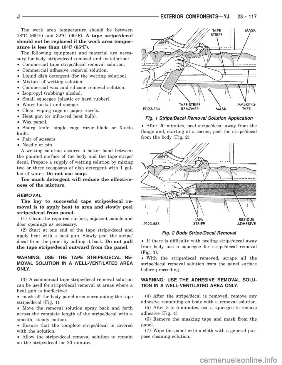
stripe/decal (Fig. 1).
²Move the removal solution spray back and forth
across the complete length of the stripe/decal with a
smooth, steady motion.
²Ensure that the complete stripe/decal is covered
with the solution.
²Allow the stripe/decal removal solution to remain
on the stripe/decal for 20 minutes.²After 20 minutes, peel stripe/decal away from the
flange and, starting at a corner, peel the stripe/decal
from the body (Fig. 2).
²If there is difficulty with peeling stripe/decal away
from body use a squeegee for stripe/decal removal
(Fig. 3).
²With the stripe/decal removed, scrape all the
stripe/decal removal solution from the panel surface
before proceeding.
WARNING: USE THE ADHESIVE REMOVAL SOLU-
TION IN A WELL-VENTILATED AREA ONLY.
(4) After the stripe/decal is removed, remove any
adhesive remaining on body with a removal solution.
(5) After 3 to 5 minutes, use a squeegee to remove
adhesive (Fig. 4).
(6) Remove the masking tape and mask from the
panel.
(7) Wipe the panel with a cloth with a general pur-
pose cleaning solution.
Fig. 1 Stripe/Decal Removal Solution Application
Fig. 2 Body Stripe/Decal Removal
JEXTERIOR COMPONENTSÐYJ 23 - 117
Page 2052 of 2158
DOORS
INDEX
page page
Beltline SealÐYJ........................ 142
Door Frame Glass Channel ReplacementÐYJ . . . 142
Door Weatherstrip Seal ReplacementÐYJ...... 142
Full-Metal Door Assist HandleÐYJ........... 136
Full-Metal Door HingesÐYJ................ 140
Full-Metal Door Key Lock CylinderÐYJ........ 139
Full-Metal Door Latch External Release
HandleÐYJ........................... 140
Full-Metal Door Latch Inside Release and Lock
HandleÐYJ........................... 137
Full-Metal Door LatchÐYJ.................. 140Full-Metal Door ServiceÐYJ................ 142
Full-Metal Door Trim PanelÐYJ.............. 137
Full-Metal Door Vent Window GlassÐYJ....... 137
Full-Metal Door WaterdamÐYJ.............. 137
Full-Metal Door Weatherstrip SealsÐYJ........ 141
Full-Metal Door Window Glass Regulator
HandleÐYJ........................... 136
Full-Metal Door Window Glass RegulatorÐYJ . . . 138
Full-Metal Door Window GlassÐYJ........... 139
Half-Metal Door Latch StrikerÐYJ............ 135
Half-Metal Soft Top DoorÐYJ............... 134
HALF-METAL SOFT TOP DOORÐYJ
REMOVAL/DISASSEMBLY
(1) Open the door.
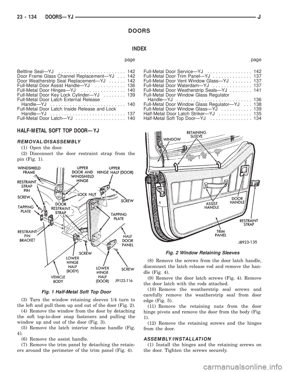
(2) Disconnect the door restraint strap from the
pin (Fig. 1).
(3) Turn the window retaining sleeves 1/4 turn to
the left and pull them up and out of the door (Fig. 2).
(4) Remove the window from the door by detaching
the soft top-to-door snap fasteners and pulling the
window up and out of the door (Fig. 3).
(5) Remove the latch interior release handle (Fig.
4).
(6) Remove the assist handle.
(7) Remove the trim panel by detaching the retain-
ers around the perimeter of the trim panel (Fig. 4).(8) Remove the screws from the door latch handle,
disconnect the latch release rod and remove the han-
dle (Fig. 4).
(9) Remove the door latch screws (Fig. 4). Remove
the door latch with the rods attached.
(10) Remove the weatherstrip seal screws and
carefully remove the weatherstrip seal from door
edge (Fig. 5).
(11) Remove the retaining nuts from the door
hinge pivots and remove the door from the body (Fig.
1).
(12) Remove the retaining screws and the hinges
from the door.
ASSEMBLY/INSTALLATION
(1) Install the hinges and the retaining screws on
the door. Tighten the screws securely.
Fig. 1 Half-Metal Soft Top Door
Fig. 2 Window Retaining Sleeves
23 - 134 DOORSÐYJJ
Page 2053 of 2158
(2) Position the door at the vehicle, insert the
hinge pivots in the hinge receptacles and install the
retaining nuts (Fig. 1). Tighten the nuts securely.
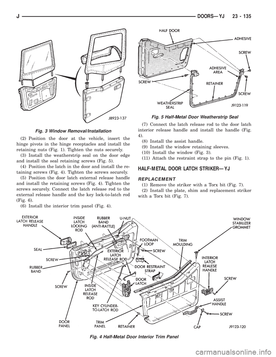
(3) Install the weatherstrip seal on the door edge
and install the seal retaining screws (Fig. 5).
(4) Position the latch in the door and install the re-
taining screws (Fig. 4). Tighten the screws securely.
(5) Position the door latch external release handle
and install the retaining screws (Fig. 4). Tighten the
screws securely. Connect the latch release rod to the
external release handle and the key lock-to-latch rod
(Fig. 6).
(6) Install the interior trim panel (Fig. 4).(7) Connect the latch release rod to the door latch
interior release handle and install the handle (Fig.
4).
(8) Install the assist handle.
(9) Install the window retaining sleeves.
(10) Install the window (Fig. 3).
(11) Attach the restraint strap to the pin (Fig. 1).
HALF-METAL DOOR LATCH STRIKERÐYJ
REPLACEMENT
(1) Remove the striker with a Torx bit (Fig. 7).
(2) Install the plate, shim and replacement striker
with a Torx bit (Fig. 7).
Fig. 4 Half-Metal Door Interior Trim Panel
Fig. 3 Window Removal/Installation
Fig. 5 Half-Metal Door Weatherstrip Seal
JDOORSÐYJ 23 - 135
Page 2057 of 2158
(3) Slide the regulator arm guide onto the regula-
tor arm and position the guide on the window glass
(Fig. 12). Install the nuts, bushings and screws.
(4) Install the division channel lower adjustment
screw.
(5) Test the window glass for proper operation.
(6) Install the door waterdam and the trim panel
(Fig. 8 and 10).
FULL-METAL DOOR WINDOW GLASSÐYJ
ADJUSTMENT
One adjustment location provides amount of effort
required to raise and lower the door window glass.
The door window glass division channel is adjustable
fore and aft at the lower attaching location.
(1) Remove the door trim panel and the waterdam
(Fig. 8 and 10).
(2) Loosen channel lower adjustment screw and
move the division channel fore or aft to obtain the
desired door window glass operation.
Movement of the division channel fore or aft
will decrease or increase the free-play between
the channels.
(3) Tighten the division channel lower adjustment
screw.
(4) Install the door waterdam and the trim panel
(Fig. 8 and 10).
REMOVAL
(1) Remove the door trim panel and the waterdam
(Fig. 8 and 10).
(2) Remove the window glass down-stop bumper
(Fig. 11).
(3) Remove the screws that attach the regulator
arm guide to the window glass. Remove the screws,
bushings, nuts and the guide from the glass (Fig. 11).
(4) Lower the window glass to the bottom of the
door.
(5) Remove the division channel upper attaching
screw and the lower adjustment screw. Detach the
front 3 inches of window glass weatherstrip seal from
the door upper frame.
(6) Separate the division channel from the front
window glass rubber seal. Pull the division channel
up and in toward the inside of vehicle.
(7) Raise and tilt the window glass toward the
hinge side of the door and disengage it from the rear
channel.
(8) Pull the window glass up and out of the door
panel.
INSTALLATION
(1) Lower the window glass into the door, while in-
serting the window glass into the front and rear
channels.
(2) Slide the window glass downward to the bottom
of the door panel.(3) Lower the division channel into the door and
position the window glass securely in the channel.
(4) Install the weatherstrip seal in the upper door
frame and install the upper attaching screw and the
lower adjustment screw.
(5) Slide the guide onto the regulator arm and po-
sition the guide on the window glass. Install the re-
taining nuts, bushings and screws (Fig. 12).
(6) Install the window glass down-stop bumper
(Fig. 11).
(7) Test the window operation for proper adjust-
ment.
(8) Install the door waterdam and the trim panel
(Fig. 8 and 10).
FULL-METAL DOOR KEY LOCK CYLINDERÐYJ
REMOVAL
(1) Remove the door trim panel and the waterdam
(Fig. 8 and 10).
(2) Remove the door latch cover screws and remove
the cover (Fig. 11).
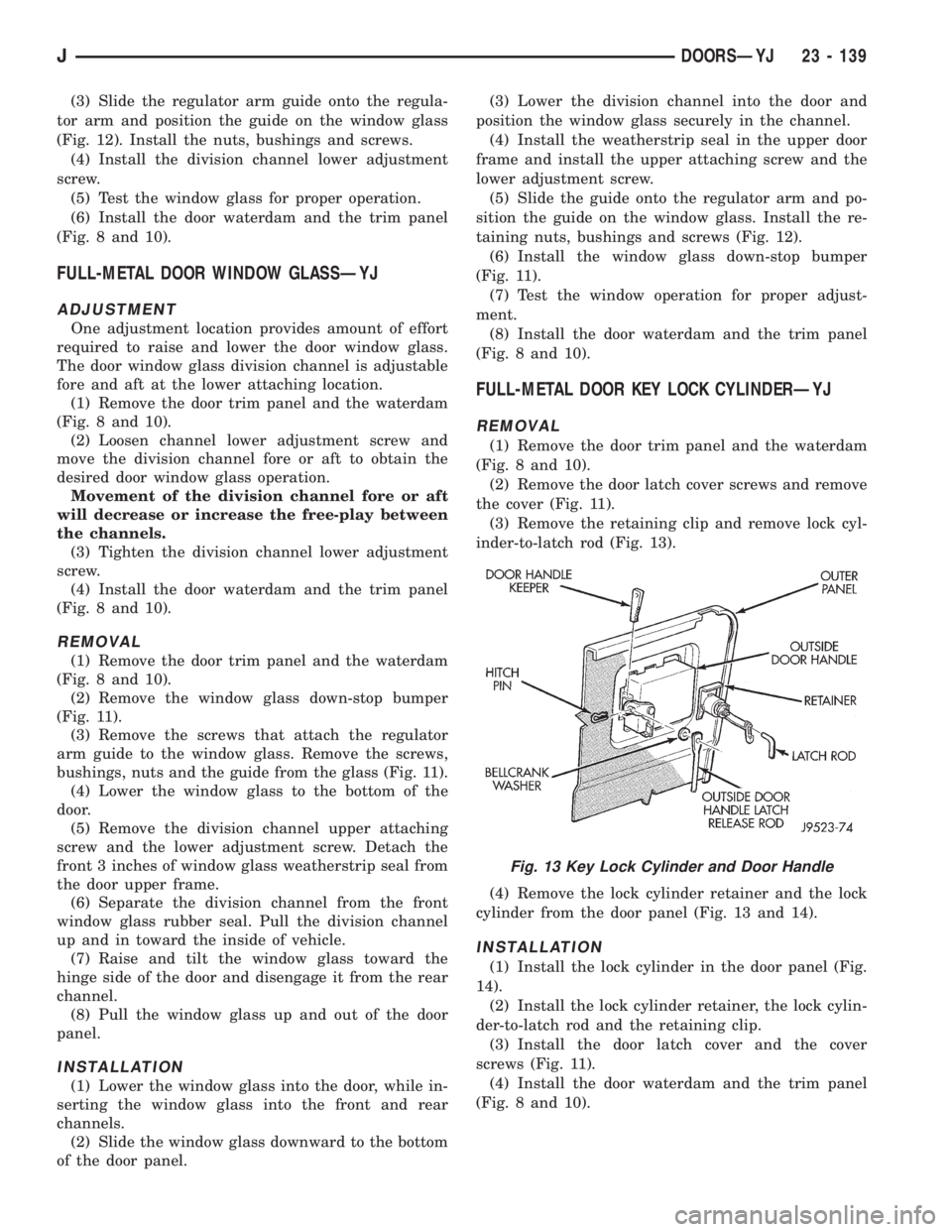
(3) Remove the retaining clip and remove lock cyl-
inder-to-latch rod (Fig. 13).
(4) Remove the lock cylinder retainer and the lock
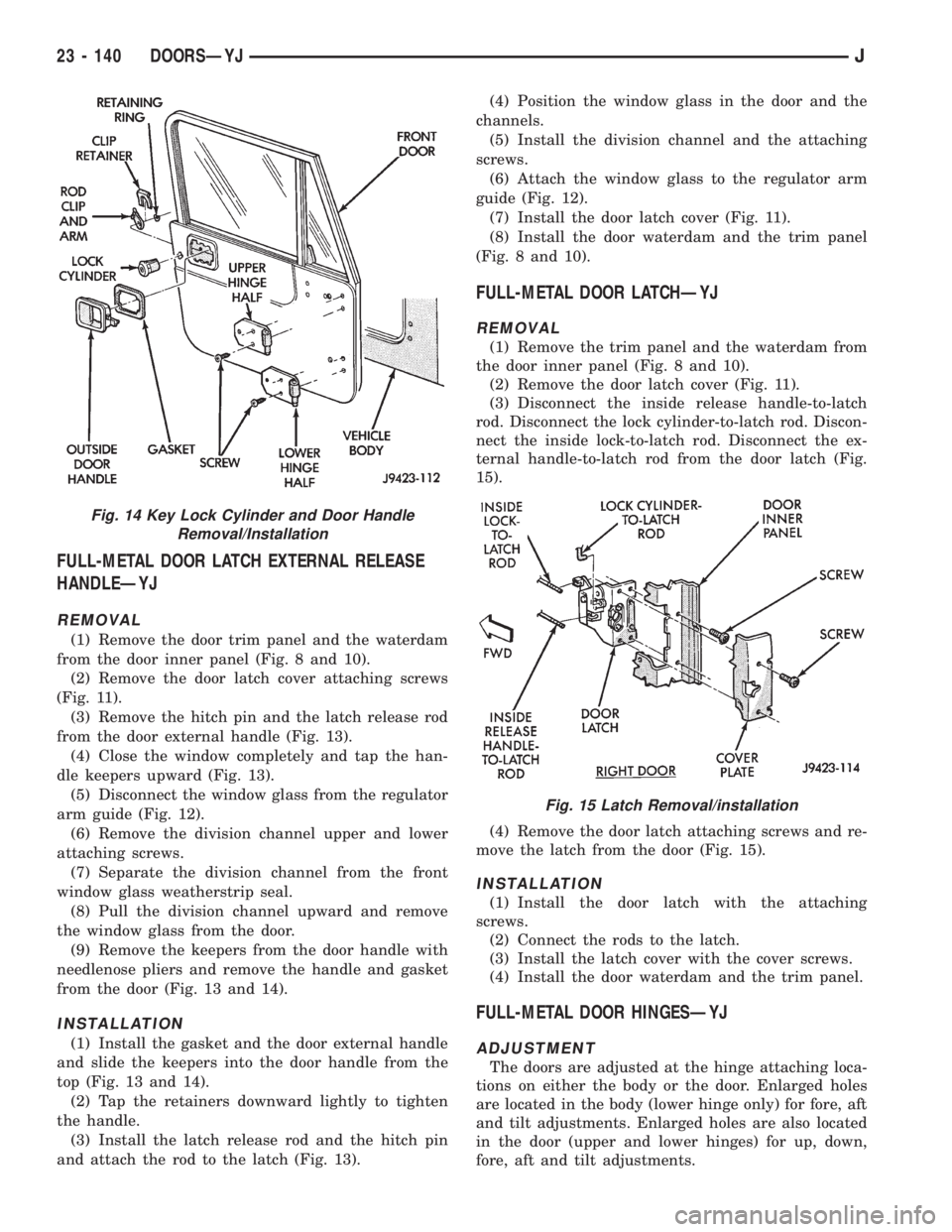
cylinder from the door panel (Fig. 13 and 14).
INSTALLATION
(1) Install the lock cylinder in the door panel (Fig.
14).
(2) Install the lock cylinder retainer, the lock cylin-
der-to-latch rod and the retaining clip.
(3) Install the door latch cover and the cover
screws (Fig. 11).
(4) Install the door waterdam and the trim panel
(Fig. 8 and 10).
Fig. 13 Key Lock Cylinder and Door Handle
JDOORSÐYJ 23 - 139
Page 2058 of 2158
FULL-METAL DOOR LATCH EXTERNAL RELEASE
HANDLEÐYJ
REMOVAL
(1) Remove the door trim panel and the waterdam
from the door inner panel (Fig. 8 and 10).
(2) Remove the door latch cover attaching screws
(Fig. 11).
(3) Remove the hitch pin and the latch release rod
from the door external handle (Fig. 13).
(4) Close the window completely and tap the han-
dle keepers upward (Fig. 13).
(5) Disconnect the window glass from the regulator
arm guide (Fig. 12).
(6) Remove the division channel upper and lower
attaching screws.
(7) Separate the division channel from the front
window glass weatherstrip seal.
(8) Pull the division channel upward and remove
the window glass from the door.
(9) Remove the keepers from the door handle with
needlenose pliers and remove the handle and gasket
from the door (Fig. 13 and 14).
INSTALLATION
(1) Install the gasket and the door external handle
and slide the keepers into the door handle from the
top (Fig. 13 and 14).
(2) Tap the retainers downward lightly to tighten
the handle.
(3) Install the latch release rod and the hitch pin
and attach the rod to the latch (Fig. 13).(4) Position the window glass in the door and the
channels.
(5) Install the division channel and the attaching
screws.
(6) Attach the window glass to the regulator arm
guide (Fig. 12).
(7) Install the door latch cover (Fig. 11).
(8) Install the door waterdam and the trim panel
(Fig. 8 and 10).
FULL-METAL DOOR LATCHÐYJ
REMOVAL
(1) Remove the trim panel and the waterdam from
the door inner panel (Fig. 8 and 10).
(2) Remove the door latch cover (Fig. 11).
(3) Disconnect the inside release handle-to-latch
rod. Disconnect the lock cylinder-to-latch rod. Discon-
nect the inside lock-to-latch rod. Disconnect the ex-
ternal handle-to-latch rod from the door latch (Fig.
15).
(4) Remove the door latch attaching screws and re-
move the latch from the door (Fig. 15).
INSTALLATION
(1) Install the door latch with the attaching
screws.
(2) Connect the rods to the latch.
(3) Install the latch cover with the cover screws.
(4) Install the door waterdam and the trim panel.
FULL-METAL DOOR HINGESÐYJ
ADJUSTMENT
The doors are adjusted at the hinge attaching loca-
tions on either the body or the door. Enlarged holes
are located in the body (lower hinge only) for fore, aft
and tilt adjustments. Enlarged holes are also located
in the door (upper and lower hinges) for up, down,
fore, aft and tilt adjustments.
Fig. 14 Key Lock Cylinder and Door Handle
Removal/Installation
Fig. 15 Latch Removal/installation
23 - 140 DOORSÐYJJ
Page 2060 of 2158
DOOR WEATHERSTRIP SEAL REPLACEMENTÐYJ
REMOVAL
(1) Carefully remove the weatherstrip seal from
the door with a weatherstrip seal removal tool. Pry
the seal outward to separate the plastic retainers
from the door panel holes.
(2) Remove the upper portion of the seal from the
door upper frame with your fingers or a wooden
wand.
(3) Remove the dust and residual adhesive from
the door panel and body panel.
INSTALLATION
(1) Apply adhesive to the front, rear and bottom
edges of the door from the beltline downward.
(2) Install the upper front corner of the seal on the
door first using your fingers or a wooden wand to po-
sition the seal in the channel. Place the inner shoul-
der of the seal in the channel-to-window frame above
the beltline.
(3) Force the retainers, starting at the rear edge of
the door, into the door panel holes.
(4) Ensure that the seal is completely seated
around the door.
BELTLINE SEALÐYJ
REMOVAL
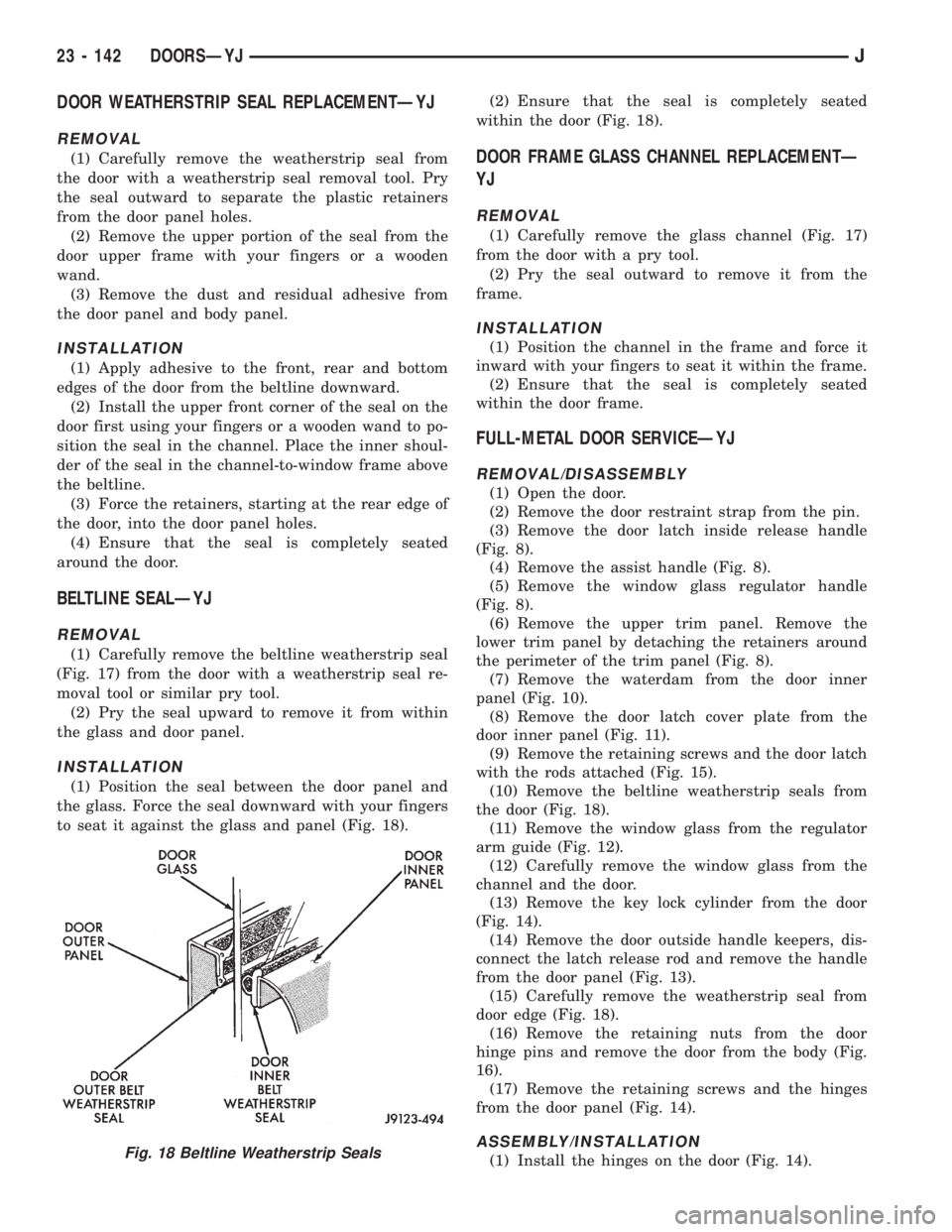
(1) Carefully remove the beltline weatherstrip seal
(Fig. 17) from the door with a weatherstrip seal re-
moval tool or similar pry tool.
(2) Pry the seal upward to remove it from within
the glass and door panel.
INSTALLATION
(1) Position the seal between the door panel and
the glass. Force the seal downward with your fingers
to seat it against the glass and panel (Fig. 18).(2) Ensure that the seal is completely seated
within the door (Fig. 18).
DOOR FRAME GLASS CHANNEL REPLACEMENTÐ
YJ
REMOVAL
(1) Carefully remove the glass channel (Fig. 17)
from the door with a pry tool.
(2) Pry the seal outward to remove it from the
frame.
INSTALLATION
(1) Position the channel in the frame and force it
inward with your fingers to seat it within the frame.
(2) Ensure that the seal is completely seated
within the door frame.
FULL-METAL DOOR SERVICEÐYJ
REMOVAL/DISASSEMBLY
(1) Open the door.
(2) Remove the door restraint strap from the pin.
(3) Remove the door latch inside release handle
(Fig. 8).
(4) Remove the assist handle (Fig. 8).
(5) Remove the window glass regulator handle
(Fig. 8).
(6) Remove the upper trim panel. Remove the
lower trim panel by detaching the retainers around
the perimeter of the trim panel (Fig. 8).
(7) Remove the waterdam from the door inner
panel (Fig. 10).
(8) Remove the door latch cover plate from the
door inner panel (Fig. 11).
(9) Remove the retaining screws and the door latch
with the rods attached (Fig. 15).
(10) Remove the beltline weatherstrip seals from
the door (Fig. 18).
(11) Remove the window glass from the regulator
arm guide (Fig. 12).
(12) Carefully remove the window glass from the
channel and the door.
(13) Remove the key lock cylinder from the door
(Fig. 14).
(14) Remove the door outside handle keepers, dis-
connect the latch release rod and remove the handle
from the door panel (Fig. 13).
(15) Carefully remove the weatherstrip seal from
door edge (Fig. 18).
(16) Remove the retaining nuts from the door
hinge pins and remove the door from the body (Fig.
16).
(17) Remove the retaining screws and the hinges
from the door panel (Fig. 14).
ASSEMBLY/INSTALLATION
(1) Install the hinges on the door (Fig. 14).Fig. 18 Beltline Weatherstrip Seals
23 - 142 DOORSÐYJJ
Page 2061 of 2158
(2) Position the door at the body opening, insert
the hinge pins in the hinge receptacles and install
the retaining nuts (Fig. 16). Tighten the nuts se-
curely.
(3) Install the weatherstrip seal on the door edge
(Fig. 18).
(4) Install the door outside handle and the keepers.
Connect the latch release rod to the handle (Fig. 13).
(5) Install the key lock cylinder (Fig. 14).
(6) Position the window glass in the channel and
the door.
(7) Attach the window glass to the regulator arm
guide (Fig. 12).
(8) Install the beltline weatherstrip seals in the
door (Fig. 18).
(9) Position the latch in the door and install the re-
taining screws (Fig. 15). Tighten the screws securely.
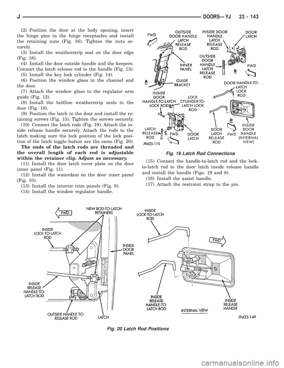
(10) Connect the latch rods (Fig. 19). Attach the in-
side release handle securely. Attach the rods to the
latch making sure the lock position of the lock posi-
tion of the latch toggle button are the same (Fig. 20).
The ends of the latch rods are threaded and
the overall length of each rod is adjustable
within the retainer clip. Adjust as necessary.
(11) Install the door latch cover plate on the door
inner panel (Fig. 11).
(12) Install the waterdam on the door inner panel
(Fig. 10).
(13) Install the interior trim panels (Fig. 8).
(14) Install the window regulator handle.(15) Connect the handle-to-latch rod and the lock-
to-latch rod to the door latch inside release handle
and install the handle (Figs. 19 and 8).
(16) Install the assist handle.
(17) Attach the restraint strap to the pin.
Fig. 19 Latch Rod Connections
Fig. 20 Latch Rod Positions
JDOORSÐYJ 23 - 143