Page 1964 of 2158
(2) Tighten the glass attaching screw 6 Nzm (53 in-
lbs) torque.(3) Install the window glass channel/division bar in
the door.
(4) Install the window glass channel/division bar
screws and rivet. Tighten the screws to 6 Nzm(5ft-
lbs) torque.
(5) Install the window glass channel and belt
weatherstrip seals (Fig. 10 and 11).
(6) Install the window beltline molding.
(7) Install the door waterdam and trim panel.
REAR DOOR STATIONARY WINDOW GLASSÐXJ
REMOVAL
(1) Lower the window glass.
(2) Pry the window beltline molding away from the
clips and remove the molding from the door.
Fig. 7 Window Channel/Division Bar Screws and
Rivet
Fig. 8 Window Channel/Division Bar Rivet
Fig. 9 Regulator-To-Glass Screw Removal/
Installation
Fig. 10 Glass Channel Weatherstrip Seal
Fig. 11 Belt Weatherstrip Seals
23 - 46 DOORSÐXJJ
Page 1965 of 2158

(3) Remove the window weatherstrip seals from
the door.
(4) Remove the trim panel and waterdam from
door inner panel.
(5) Remove the channel/division bar screws. Drill
out the rivet head to remove it from the inner panel.
(6) Tilt the channel/division bar forward and re-
move it from the door.
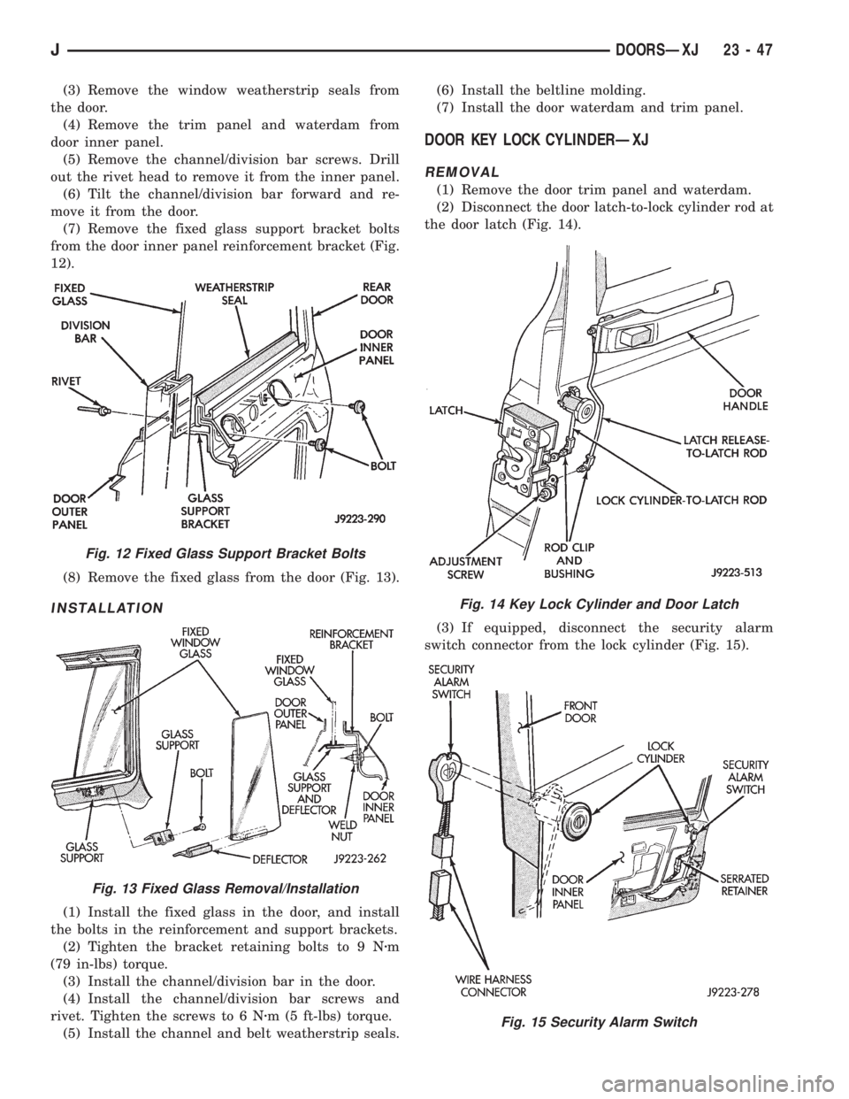
(7) Remove the fixed glass support bracket bolts
from the door inner panel reinforcement bracket (Fig.
12).
(8) Remove the fixed glass from the door (Fig. 13).
INSTALLATION
(1) Install the fixed glass in the door, and install
the bolts in the reinforcement and support brackets.
(2) Tighten the bracket retaining bolts to 9 Nzm
(79 in-lbs) torque.
(3) Install the channel/division bar in the door.
(4) Install the channel/division bar screws and
rivet. Tighten the screws to 6 Nzm (5 ft-lbs) torque.
(5) Install the channel and belt weatherstrip seals.(6) Install the beltline molding.
(7) Install the door waterdam and trim panel.
DOOR KEY LOCK CYLINDERÐXJ
REMOVAL
(1) Remove the door trim panel and waterdam.
(2) Disconnect the door latch-to-lock cylinder rod at
the door latch (Fig. 14).
(3) If equipped, disconnect the security alarm
switch connector from the lock cylinder (Fig. 15).
Fig. 12 Fixed Glass Support Bracket Bolts
Fig. 13 Fixed Glass Removal/Installation
Fig. 14 Key Lock Cylinder and Door Latch
Fig. 15 Security Alarm Switch
JDOORSÐXJ 23 - 47
Page 1969 of 2158
(2) Move the door release handle outward and dis-
connect the handle-to-latch rods (Fig. 3). For vehicles
equipped with power door locks/windows, also discon-
nect the wire harness connector (Fig. 4).
(4) Drill-out the rivet heads and remove the rod
guide bracket rivets from the door inner panel (Fig. 5
and 6).
(5) Remove the rod guide brackets and rods from
the door.
INSTALLATION
(1) Position the rod guide brackets and rods in the
door.
(2) Install rod the guide bracket rivets in the door
inner panel (Fig. 7).
(3) Install the door trim panel and waterdam.
(4) Adjust the door latch as described in DOOR
LATCH ADJUSTMENT.
Fig. 3 Door Inside Latch Release Rods
Fig. 4 Power Switch Wire Harness Connector 16
(3) Remove the door trim panel and waterdam.
Fig. 5 Front Door Rod Guide Bracket and Rods
Fig. 6 Rear Door Rod Guide Bracket and Rods
Fig. 7 Rod Guide Bracket Installation
JDOORSÐXJ 23 - 51
Page 1971 of 2158
14). Be careful not to bend the hinge when driving
the hinge pin, support may be required under the
hinge.
(8) Adjust/align latch striker and latch as neces-
sary.(9) Install the door restraint (check) retaining pin
with a punch.
FRONT DOOR SPACER BLOCKSÐTWO-DOOR
VEHICLES
REMOVAL
(1) Upper spacer block: drill-out the rivet heads
and remove them from the reinforcement plate (Fig.
1).
(2) Lower spacer block: remove the screws from the
door face (Fig. 2).
(3) As applicable, remove the spacer block from the
door window frame or door face.
INSTALLATION
(1) As applicable, position the spacer block on the
door window frame or door face.
(2) Upper spacer block: Install the replacement riv-
ets in the spacer block and reinforcement plate.
Fig 11 Install Bushing In Hinge
Fig. 12 Begin To Roll Bushing Material Outward
Fig. 13 Forming A Head On The Bushing
Fig. 14 Installing The Hinge Pin
Fig. 1 Front Door Upper Spacer BlockÐTwo-Door
Vehicles
JDOORSÐXJ 23 - 53
Page 1972 of 2158
(3) Lower spacer block: install the screws in the
door face. Tighten the screws to 1 Nzm (11 in-lbs)
torque.
DOOR EDGE GUARD/EDGE PROTECTOR
STRIPÐXJ
REPLACEMENT
(1) Pull outward and remove the door edge guard
strip from the door edge (Fig. 3).
(2) Position the door edge guard strip on the door
edge.
(3) Force the door edge guard strip inward until it
is seated on the door edge.
DOOR WINDOW EXTERIOR MOLDINGSÐXJ
REMOVAL
(1) When removing the front or rear door window
exterior molding, open the window completely (Fig. 4
and 5).
(2) Pry and pull the molding sections from the door
panel flange and clips.
Fig. 3 Door Edge Guard/Protector Strip
Fig. 4 Front Door Window Exterior Molding
Fig. 2 Front Door Lower Spacer BlockÐTwo-Door
Vehicles
23 - 54 DOORSÐXJJ
Page 1973 of 2158
INSTALLATION
(1) When installing window moldings, start at the
forward end of the upper molding.
(2) Force the molding onto the door panel and con-
tinue rearward until it is completely seated on the
flange.
(3) Mate the rear molding with the upper molding
and force the molding edge inward.
(4) Continue pressing and moving downward to
complete the installation.
(5) Position the lower molding on the clips and
force it downward.
DOOR WINDOW GLASS AND DOOR OPENING
WEATHERSTRIP SEALSÐXJ
REMOVAL
When removing the front or rear door window glass
weatherstrip seals, open the window.
The window weatherstrip seals (Fig. 6 and 7) can
be removed by hand or with the aid of a small putty
knife (or similar tool).
Fig. 6 Front Door Window Glass Weatherstrip Seals
Fig. 5 Rear Door Window Exterior Molding
Fig. 7 Rear Door Window Glass Weatherstrip Seals
JDOORSÐXJ 23 - 55
Page 1974 of 2158

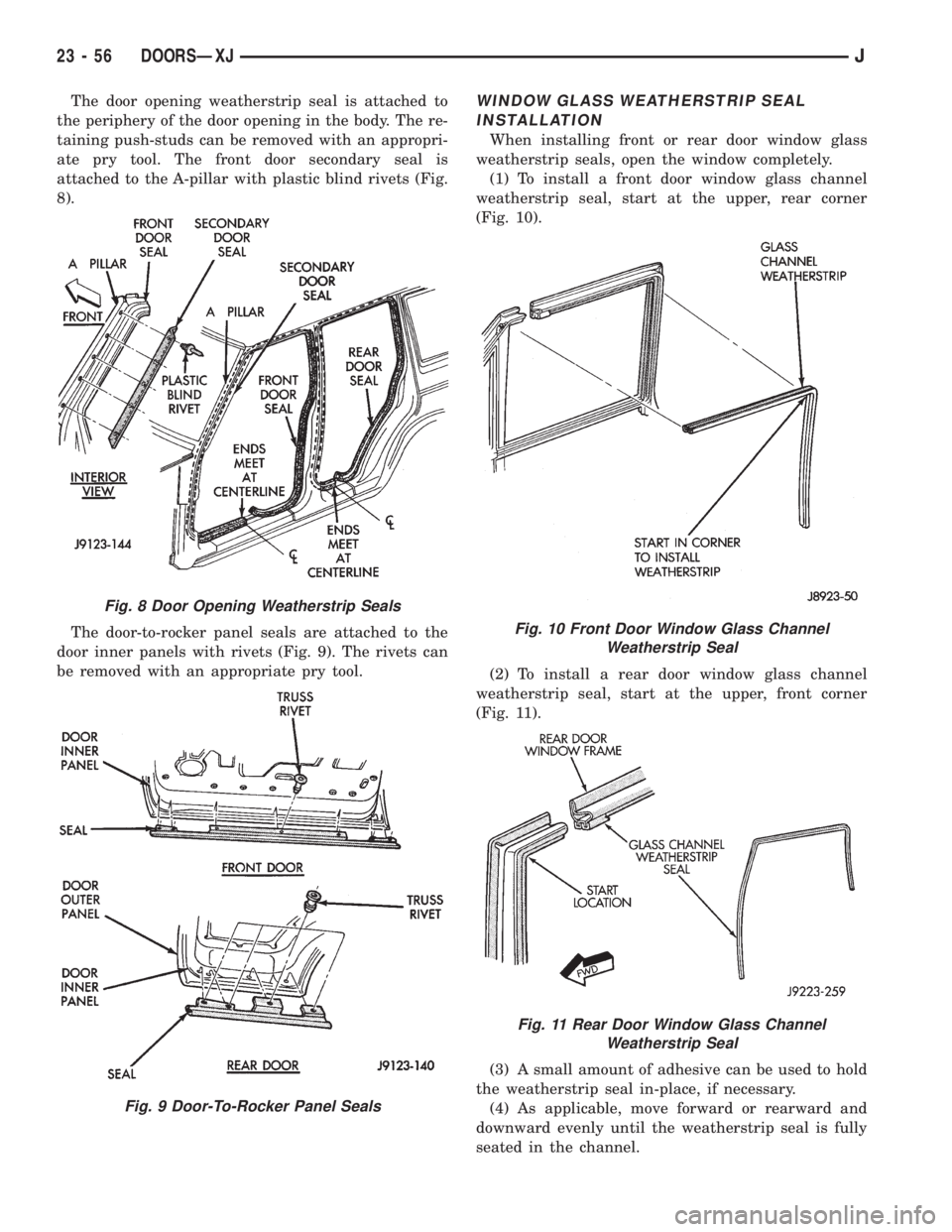
The door opening weatherstrip seal is attached to
the periphery of the door opening in the body. The re-
taining push-studs can be removed with an appropri-
ate pry tool. The front door secondary seal is
attached to the A-pillar with plastic blind rivets (Fig.
8).
The door-to-rocker panel seals are attached to the
door inner panels with rivets (Fig. 9). The rivets can
be removed with an appropriate pry tool.WINDOW GLASS WEATHERSTRIP SEAL
INSTALLATION
When installing front or rear door window glass
weatherstrip seals, open the window completely.
(1) To install a front door window glass channel
weatherstrip seal, start at the upper, rear corner
(Fig. 10).
(2) To install a rear door window glass channel
weatherstrip seal, start at the upper, front corner
(Fig. 11).
(3) A small amount of adhesive can be used to hold
the weatherstrip seal in-place, if necessary.
(4) As applicable, move forward or rearward and
downward evenly until the weatherstrip seal is fully
seated in the channel.
Fig. 8 Door Opening Weatherstrip Seals
Fig. 9 Door-To-Rocker Panel Seals
Fig. 10 Front Door Window Glass Channel
Weatherstrip Seal
Fig. 11 Rear Door Window Glass Channel
Weatherstrip Seal
23 - 56 DOORSÐXJJ
Page 1984 of 2158

STATIONARY WINDOW GLASS
INDEX
page page
Interior Rearview MirrorÐXJ Removal and
Installation............................. 66
Interior Rearview Mirror Support Bracket
ReplacementÐXJ Preparation and Installation . . . 66
Description and Operation.......... ..........67
InstallationÐShort Method.......... ..........69
InstallationÐExtended Method........ ........71Rear Door Stationary Window Glass...... ......72
Rear Quarter Vent Window GlassÐXJ Removal
and Installation............. .............73
Rear Quarter Window Glass/Rear Quarter Plastic
InsertÐXJ Removal and Installation..... .....73
INTERIOR REARVIEW MIRRORÐXJ
MIRROR REMOVAL
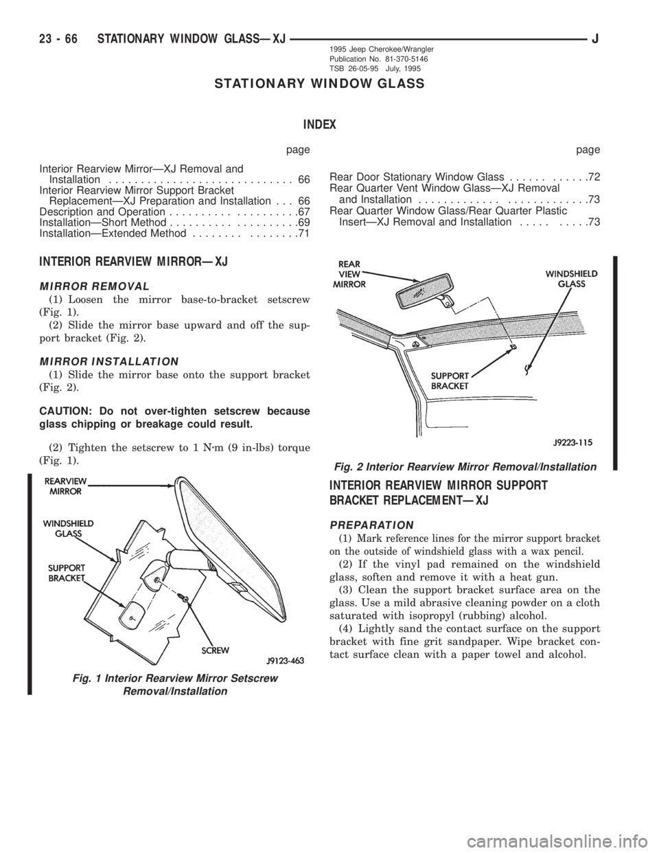
(1) Loosen the mirror base-to-bracket setscrew
(Fig. 1).
(2) Slide the mirror base upward and off the sup-
port bracket (Fig. 2).
MIRROR INSTALLATION
(1) Slide the mirror base onto the support bracket
(Fig. 2).
CAUTION: Do not over-tighten setscrew because
glass chipping or breakage could result.
(2) Tighten the setscrew to 1 Nzm (9 in-lbs) torque
(Fig. 1).
INTERIOR REARVIEW MIRROR SUPPORT
BRACKET REPLACEMENTÐXJ
PREPARATION
(1) Mark reference lines for the mirror support bracket
on the outside of windshield glass with a wax pencil.
(2) If the vinyl pad remained on the windshield
glass, soften and remove it with a heat gun.
(3) Clean the support bracket surface area on the
glass. Use a mild abrasive cleaning powder on a cloth
saturated with isopropyl (rubbing) alcohol.
(4) Lightly sand the contact surface on the support
bracket with fine grit sandpaper. Wipe bracket con-
tact surface clean with a paper towel and alcohol.
Fig. 1 Interior Rearview Mirror Setscrew
Removal/Installation
Fig. 2 Interior Rearview Mirror Removal/Installation
23 - 66 STATIONARY WINDOW GLASSÐXJJ1995 Jeep Cherokee/Wrangler
Publication No. 81-370-5146
TSB 26-05-95 July, 1995