1995 JEEP YJ water pump
[x] Cancel search: water pumpPage 1370 of 2158
REMOVAL
(1) Remove the engine flywheel or converter drive
plate.
(2) Remove the oil pan.
(3) Remove the rear main bearing cap (No.7).
(4) Push the upper seal out of the groove. Ensure
that the crankshaft and seal groove are not damaged.
(5) Remove the lower half of the seal from the
bearing cap.
INSTALLATION
(1) Wipe the seal surface area of the crankshaft
until it is clean.
(2) Apply a thin coat of engine oil.
(3) Coat the lip of the seal with engine oil.
(4) Carefully position the upper seal into the
groove in the cylinder block. The lip of the seal faces
toward the front of the engine.
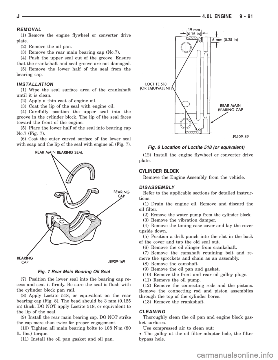
(5) Place the lower half of the seal into bearing cap
No.7 (Fig. 7).
(6) Coat the outer curved surface of the lower seal
with soap and the lip of the seal with engine oil (Fig. 7).
(7) Position the lower seal into the bearing cap re-
cess and seat it firmly. Be sure the seal is flush with
the cylinder block pan rail.
(8) Apply Loctite 518, or equivalent on the rear
bearing cap (Fig. 8). The bead should be 3 mm (0.125
in) thick. DO NOT apply Loctite 518, or equivalent to
the lip of the seal.
(9) Install the rear main bearing cap. DO NOT strike
the cap more than twice for proper engagement.
(10) Tighten all main bearing bolts to 108 Nzm (80
ft. lbs.) torque.
(11) Install the oil pan gasket and oil pan.(12) Install the engine flywheel or converter drive
plate.
CYLINDER BLOCK
Remove the Engine Assembly from the vehicle.
DISASSEMBLY
Refer to the applicable sections for detailed instruc-
tions.
(1) Drain the engine oil. Remove and discard the
oil filter.
(2) Remove the water pump from the cylinder block.
(3) Remove the vibration damper.
(4) Remove the timing case cover and lay the cover
upside down.
(5) Position a drift punch into the slot in the back
of the cover and tap the old seal out.
(6) Remove the oil slinger from crankshaft.
(7) Remove the camshaft retaining bolt and re-
move the sprockets and chain as an assembly.
(8) Remove the camshaft.
(9) Remove the oil pan and gasket.
(10) Remove the front and rear oil galley plugs.
(11) Remove the oil pump.
(12) Remove the connecting rods and the pistons.
Remove the connecting rod and piston assemblies
through the top of the cylinder bores.
(13) Remove the crankshaft.
CLEANING
Thoroughly clean the oil pan and engine block gas-
ket surfaces.
Use compressed air to clean out:
²The galley at the oil filter adaptor hole, the filter
bypass hole.
Fig. 7 Rear Main Bearing Oil Seal
Fig. 8 Location of Loctite 518 (or equivalent)
J4.0L ENGINE 9 - 91
Page 1371 of 2158
²The front and rear oil galley holes.
²The feed holes for the crankshaft main bearings.
Once the block has been completely cleaned, apply
Loctite PST pipe sealant with Teflon 592 to the
threads of the front and rear oil galley plugs. Tighten
the plugs to 41 Nzm (30 ft. lbs.) torque.
INSPECTIONÐCYLINDER BORE
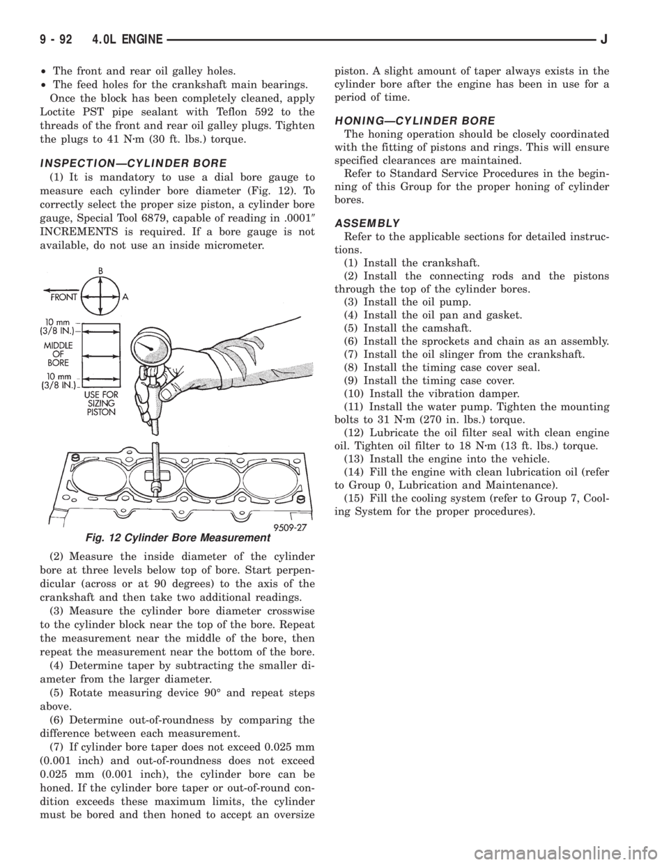
(1) It is mandatory to use a dial bore gauge to
measure each cylinder bore diameter (Fig. 12). To
correctly select the proper size piston, a cylinder bore
gauge, Special Tool 6879, capable of reading in .00019
INCREMENTS is required. If a bore gauge is not
available, do not use an inside micrometer.
(2) Measure the inside diameter of the cylinder
bore at three levels below top of bore. Start perpen-
dicular (across or at 90 degrees) to the axis of the
crankshaft and then take two additional readings.
(3) Measure the cylinder bore diameter crosswise
to the cylinder block near the top of the bore. Repeat
the measurement near the middle of the bore, then
repeat the measurement near the bottom of the bore.
(4) Determine taper by subtracting the smaller di-
ameter from the larger diameter.
(5) Rotate measuring device 90É and repeat steps
above.
(6) Determine out-of-roundness by comparing the
difference between each measurement.
(7) If cylinder bore taper does not exceed 0.025 mm
(0.001 inch) and out-of-roundness does not exceed
0.025 mm (0.001 inch), the cylinder bore can be
honed. If the cylinder bore taper or out-of-round con-
dition exceeds these maximum limits, the cylinder
must be bored and then honed to accept an oversizepiston. A slight amount of taper always exists in the
cylinder bore after the engine has been in use for a
period of time.
HONINGÐCYLINDER BORE
The honing operation should be closely coordinated
with the fitting of pistons and rings. This will ensure
specified clearances are maintained.
Refer to Standard Service Procedures in the begin-
ning of this Group for the proper honing of cylinder
bores.
ASSEMBLY
Refer to the applicable sections for detailed instruc-
tions.
(1) Install the crankshaft.
(2) Install the connecting rods and the pistons
through the top of the cylinder bores.
(3) Install the oil pump.
(4) Install the oil pan and gasket.
(5) Install the camshaft.
(6) Install the sprockets and chain as an assembly.
(7) Install the oil slinger from the crankshaft.
(8) Install the timing case cover seal.
(9) Install the timing case cover.
(10) Install the vibration damper.
(11) Install the water pump. Tighten the mounting
bolts to 31 Nzm (270 in. lbs.) torque.
(12) Lubricate the oil filter seal with clean engine
oil. Tighten oil filter to 18 Nzm (13 ft. lbs.) torque.
(13) Install the engine into the vehicle.
(14) Fill the engine with clean lubrication oil (refer
to Group 0, Lubrication and Maintenance).
(15) Fill the cooling system (refer to Group 7, Cool-
ing System for the proper procedures).
Fig. 12 Cylinder Bore Measurement
9 - 92 4.0L ENGINEJ
Page 1382 of 2158
INSTALLATION
(1) Install the muffler onto the catalytic converter
outlet. Ensure that the locator on the converter
aligns with the notch on the muffler, if so equipped.
Install the clamp and tighten the nuts finger tight.
(2) Install the exhaust tailpipe into the muffler
outlet. Ensure that the locator on the exhaust
tailpipe aligns with the notch on the muffler, if so
equipped. Install the clamp and tighten the nuts fin-
ger tight.
(3) Install the front exhaust tailpipe supports and
the rear exhaust tailpipe hanger. Ensure that the ex-
haust tailpipe has sufficient clearance from the floor
pan and shields.
(4) Tighten the nuts on the muffler-to-catalytic
converter and the muffler-to-exhaust tailpipe clamps
to 61 Nzm (45 ft. lbs.) torque.
(5) Lower the vehicle.
(6) Start the engine and inspect for exhaust leaks
and contact with the body panels and shields.
ENGINE EXHAUST MANIFOLDÐ2.5L ENGINE
REMOVAL
(1) Disconnect the battery negative cable.
(2) Remove all components attached to the intake
manifold.
(3) Raise the vehicle.
(4) Disconnect the exhaust pipe from the engine
exhaust manifold.
(5) Lower the vehicle.
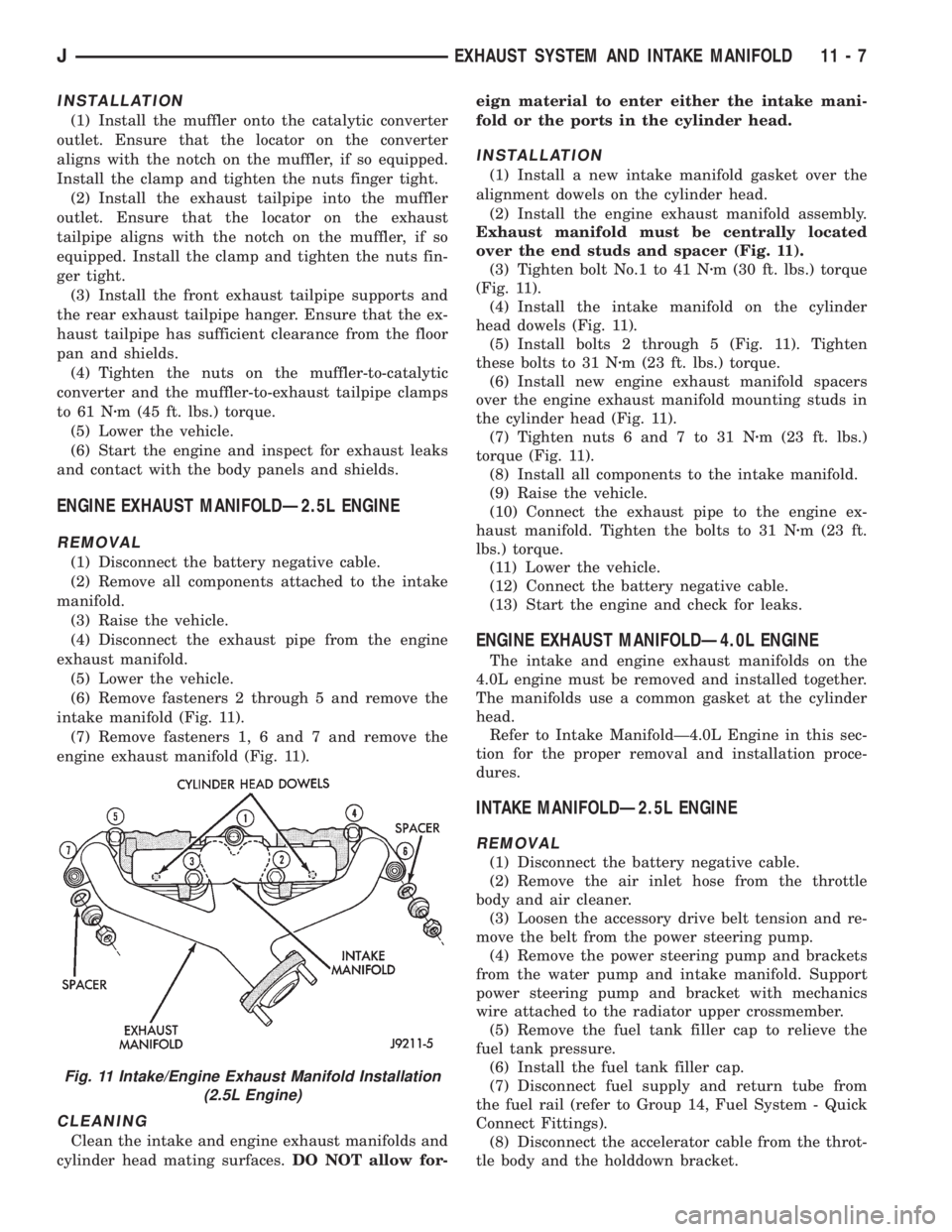
(6) Remove fasteners 2 through 5 and remove the
intake manifold (Fig. 11).
(7) Remove fasteners 1, 6 and 7 and remove the
engine exhaust manifold (Fig. 11).
CLEANING
Clean the intake and engine exhaust manifolds and
cylinder head mating surfaces.DO NOT allow for-eign material to enter either the intake mani-
fold or the ports in the cylinder head.
INSTALLATION
(1) Install a new intake manifold gasket over the
alignment dowels on the cylinder head.
(2) Install the engine exhaust manifold assembly.
Exhaust manifold must be centrally located
over the end studs and spacer (Fig. 11).
(3) Tighten bolt No.1 to 41 Nzm (30 ft. lbs.) torque
(Fig. 11).
(4) Install the intake manifold on the cylinder
head dowels (Fig. 11).
(5) Install bolts 2 through 5 (Fig. 11). Tighten
these bolts to 31 Nzm (23 ft. lbs.) torque.
(6) Install new engine exhaust manifold spacers
over the engine exhaust manifold mounting studs in
the cylinder head (Fig. 11).
(7) Tighten nuts 6 and 7 to 31 Nzm (23 ft. lbs.)
torque (Fig. 11).
(8) Install all components to the intake manifold.
(9) Raise the vehicle.
(10) Connect the exhaust pipe to the engine ex-
haust manifold. Tighten the bolts to 31 Nzm (23 ft.
lbs.) torque.
(11) Lower the vehicle.
(12) Connect the battery negative cable.
(13) Start the engine and check for leaks.
ENGINE EXHAUST MANIFOLDÐ4.0L ENGINE
The intake and engine exhaust manifolds on the
4.0L engine must be removed and installed together.
The manifolds use a common gasket at the cylinder
head.
Refer to Intake ManifoldÐ4.0L Engine in this sec-
tion for the proper removal and installation proce-
dures.
INTAKE MANIFOLDÐ2.5L ENGINE
REMOVAL
(1) Disconnect the battery negative cable.
(2) Remove the air inlet hose from the throttle
body and air cleaner.
(3) Loosen the accessory drive belt tension and re-
move the belt from the power steering pump.
(4) Remove the power steering pump and brackets
from the water pump and intake manifold. Support
power steering pump and bracket with mechanics
wire attached to the radiator upper crossmember.
(5) Remove the fuel tank filler cap to relieve the
fuel tank pressure.
(6) Install the fuel tank filler cap.
(7) Disconnect fuel supply and return tube from
the fuel rail (refer to Group 14, Fuel System - Quick
Connect Fittings).
(8) Disconnect the accelerator cable from the throt-
tle body and the holddown bracket.
Fig. 11 Intake/Engine Exhaust Manifold Installation
(2.5L Engine)
JEXHAUST SYSTEM AND INTAKE MANIFOLD 11 - 7
Page 1383 of 2158
CAUTION: When disconnecting the cruise control
connector at the throttle body, DO NOT pry the con-
nector off with pliers or screwdriver. Use finger
pressure only. Prying the connector off could break
it.
(9) Disconnect the electrical connectors. Pull the
harnesses away from the manifold.
²The throttle position sensor.
²The idle speed control motor.
²The coolant temperature sensor at the thermostat.
²The manifold air temperature sensor at the intake
manifold.
²The fuel injectors.
²The oxygen sensor.
(10) Disconnect the crankcase ventilation (CCV)
vacuum hose and manifold absolute pressure (MAP)
sensor vacuum hose connector at the intake mani-
fold.
(11) Disconnect vacuum hose from vacuum port on
the intake manifold.
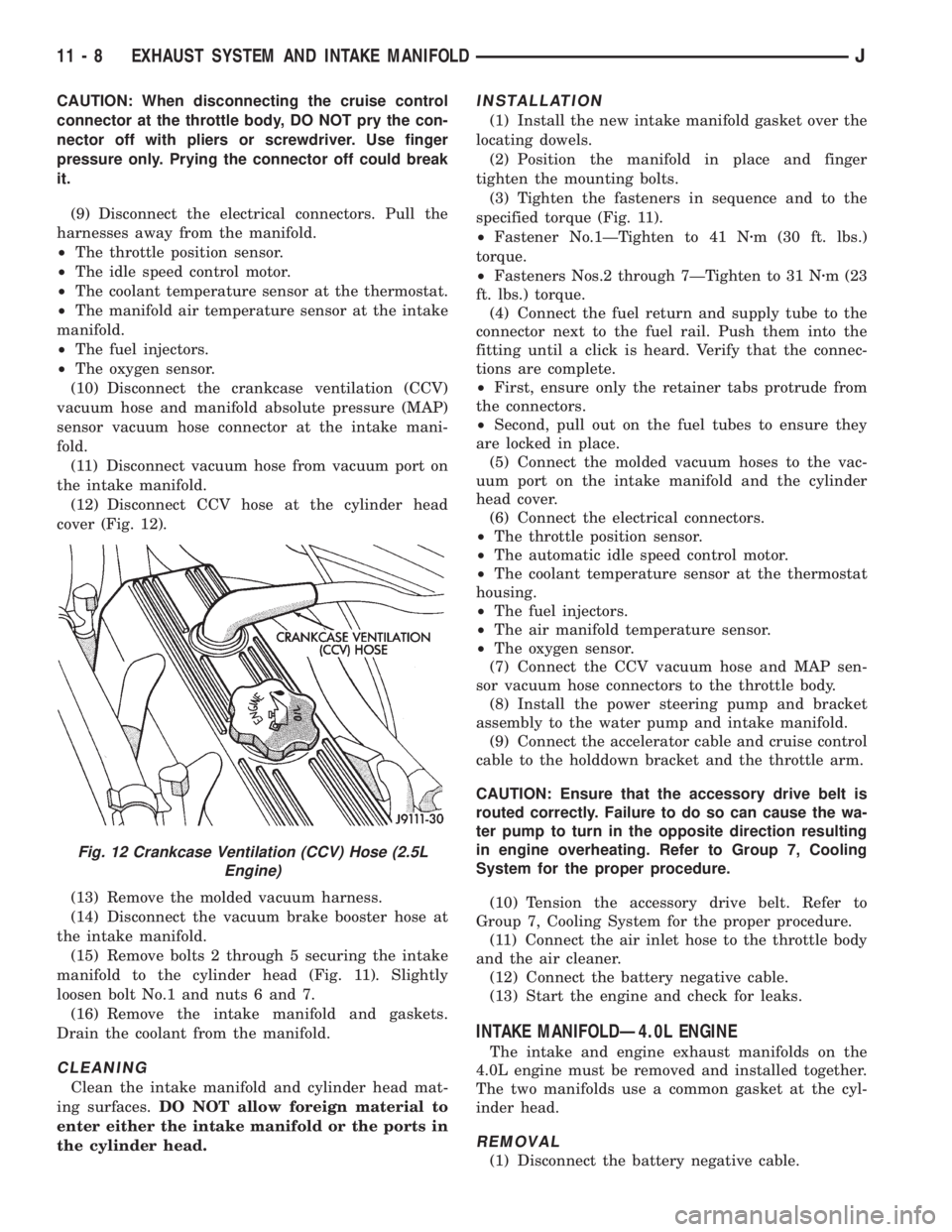
(12) Disconnect CCV hose at the cylinder head
cover (Fig. 12).
(13) Remove the molded vacuum harness.
(14) Disconnect the vacuum brake booster hose at
the intake manifold.
(15) Remove bolts 2 through 5 securing the intake
manifold to the cylinder head (Fig. 11). Slightly
loosen bolt No.1 and nuts 6 and 7.
(16) Remove the intake manifold and gaskets.
Drain the coolant from the manifold.
CLEANING
Clean the intake manifold and cylinder head mat-
ing surfaces.DO NOT allow foreign material to
enter either the intake manifold or the ports in
the cylinder head.
INSTALLATION
(1) Install the new intake manifold gasket over the
locating dowels.
(2) Position the manifold in place and finger
tighten the mounting bolts.
(3) Tighten the fasteners in sequence and to the
specified torque (Fig. 11).
²Fastener No.1ÐTighten to 41 Nzm (30 ft. lbs.)
torque.
²Fasteners Nos.2 through 7ÐTighten to 31 Nzm (23
ft. lbs.) torque.
(4) Connect the fuel return and supply tube to the
connector next to the fuel rail. Push them into the
fitting until a click is heard. Verify that the connec-
tions are complete.
²First, ensure only the retainer tabs protrude from
the connectors.
²Second, pull out on the fuel tubes to ensure they
are locked in place.
(5) Connect the molded vacuum hoses to the vac-
uum port on the intake manifold and the cylinder
head cover.
(6) Connect the electrical connectors.
²The throttle position sensor.
²The automatic idle speed control motor.
²The coolant temperature sensor at the thermostat
housing.
²The fuel injectors.
²The air manifold temperature sensor.
²The oxygen sensor.
(7) Connect the CCV vacuum hose and MAP sen-
sor vacuum hose connectors to the throttle body.
(8) Install the power steering pump and bracket
assembly to the water pump and intake manifold.
(9) Connect the accelerator cable and cruise control
cable to the holddown bracket and the throttle arm.
CAUTION: Ensure that the accessory drive belt is
routed correctly. Failure to do so can cause the wa-
ter pump to turn in the opposite direction resulting
in engine overheating. Refer to Group 7, Cooling
System for the proper procedure.
(10) Tension the accessory drive belt. Refer to
Group 7, Cooling System for the proper procedure.
(11) Connect the air inlet hose to the throttle body
and the air cleaner.
(12) Connect the battery negative cable.
(13) Start the engine and check for leaks.
INTAKE MANIFOLDÐ4.0L ENGINE
The intake and engine exhaust manifolds on the
4.0L engine must be removed and installed together.
The two manifolds use a common gasket at the cyl-
inder head.
REMOVAL
(1) Disconnect the battery negative cable.
Fig. 12 Crankcase Ventilation (CCV) Hose (2.5L
Engine)
11 - 8 EXHAUST SYSTEM AND INTAKE MANIFOLDJ
Page 1638 of 2158
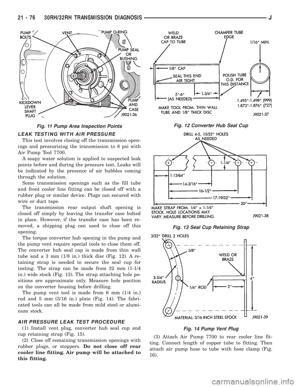
LEAK TESTING WITH AIR PRESSURE
This test involves closing off the transmission open-
ings and pressurizing the transmission to 8 psi with
Air Pump Tool 7700.
A soapy water solution is applied to suspected leak
points before and during the pressure test. Leaks will
be indicated by the presence of air bubbles coming
through the solution.
Some transmission openings such as the fill tube
and front cooler line fitting can be closed off with a
rubber plug or similar device. Plugs can secured with
wire or duct tape.
The transmission rear output shaft opening is
closed off simply by leaving the transfer case bolted
in place. However, if the transfer case has been re-
moved, a shipping plug can used to close off this
opening.
The torque converter hub opening in the pump and
the pump vent require special tools to close them off.
The converter hub seal cap is made from thin wall
tube anda3mm(1/8 in.) thick disc (Fig. 12). A re-
taining strap is needed to secure the seal cup for
testing. The strap can be made from 32 mm (1-1/4
in.) wide stock (Fig. 13). The strap attaching hole po-
sitions are approximate only. Measure hole position
on the converter housing before drilling.
The pump vent tool is made from 6 mm (1/4 in.)
rod and 5 mm (3/16 in.) plate (Fig. 14). The fabri-
cated tools can all be made from mild steel or alumi-
num stock.
AIR PRESSURE LEAK TEST PROCEDURE
(1) Install vent plug, converter hub seal cup and
cup retaining strap (Fig. 15).
(2) Close off remaining transmission openings with
rubber plugs, or stoppers.Do not close off rear
cooler line fitting. Air pump will be attached to
this fitting.(3) Attach Air Pump 7700 to rear cooler line fit-
ting. Connect length of copper tube to fitting. Then
attach air pump hose to tube with hose clamp (Fig.
16).
Fig. 11 Pump Area Inspection PointsFig. 12 Converter Hub Seal Cup
Fig. 13 Seal Cup Retaining Strap
Fig. 14 Pump Vent Plug
21 - 76 30RH/32RH TRANSMISSION DIAGNOSISJ
Page 1639 of 2158
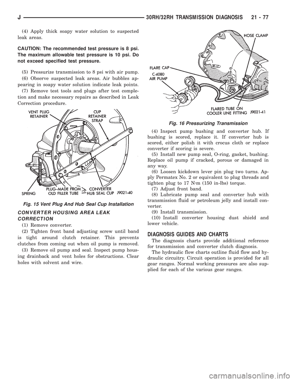
(4) Apply thick soapy water solution to suspected
leak areas.
CAUTION: The recommended test pressure is 8 psi.
The maximum allowable test pressure is 10 psi. Do
not exceed specified test pressure.
(5) Pressurize transmission to 8 psi with air pump.
(6) Observe suspected leak areas. Air bubbles ap-
pearing in soapy water solution indicate leak points.
(7) Remove test tools and plugs after test comple-
tion and make necessary repairs as described in Leak
Correction procedure.
CONVERTER HOUSING AREA LEAK
CORRECTION
(1) Remove converter.
(2) Tighten front band adjusting screw until band
is tight around clutch retainer. This prevents
clutches from coming out when oil pump is removed.
(3) Remove oil pump and seal. Inspect pump hous-
ing drainback and vent holes for obstructions. Clear
holes with solvent and wire.(4) Inspect pump bushing and converter hub. If
bushing is scored, replace it. If converter hub is
scored, either polish it with crocus cloth or replace
converter if scoring is severe.
(5) Install new pump seal, O-ring, gasket, bushing.
Replace oil pump if cracked, porous or damaged in
any way.
(6) Loosen kickdown lever pin plug two turns. Ap-
ply Permatex No. 2 or equivalent to plug threads and
tighten plug to 17 Nzm (150 in-lbs) torque.
(7) Adjust front band.
(8) Lubricate pump seal and converter hub with
transmission fluid or petroleum jelly and install con-
verter.
(9) Install transmission.
(10) Install converter housing dust shield and
lower vehicle.
DIAGNOSIS GUIDES AND CHARTS
The diagnosis charts provide additional reference
for transmission and converter clutch diagnosis.
The hydraulic flow charts outline fluid flow and hy-
draulic circuitry. Circuit operation is provided for all
gear ranges. Normal working pressures are also sup-
plied for each of the various gear ranges.
Fig. 15 Vent Plug And Hub Seal Cup Installation
Fig. 16 Pressurizing Transmission
J30RH/32RH TRANSMISSION DIAGNOSIS 21 - 77
Page 1917 of 2158
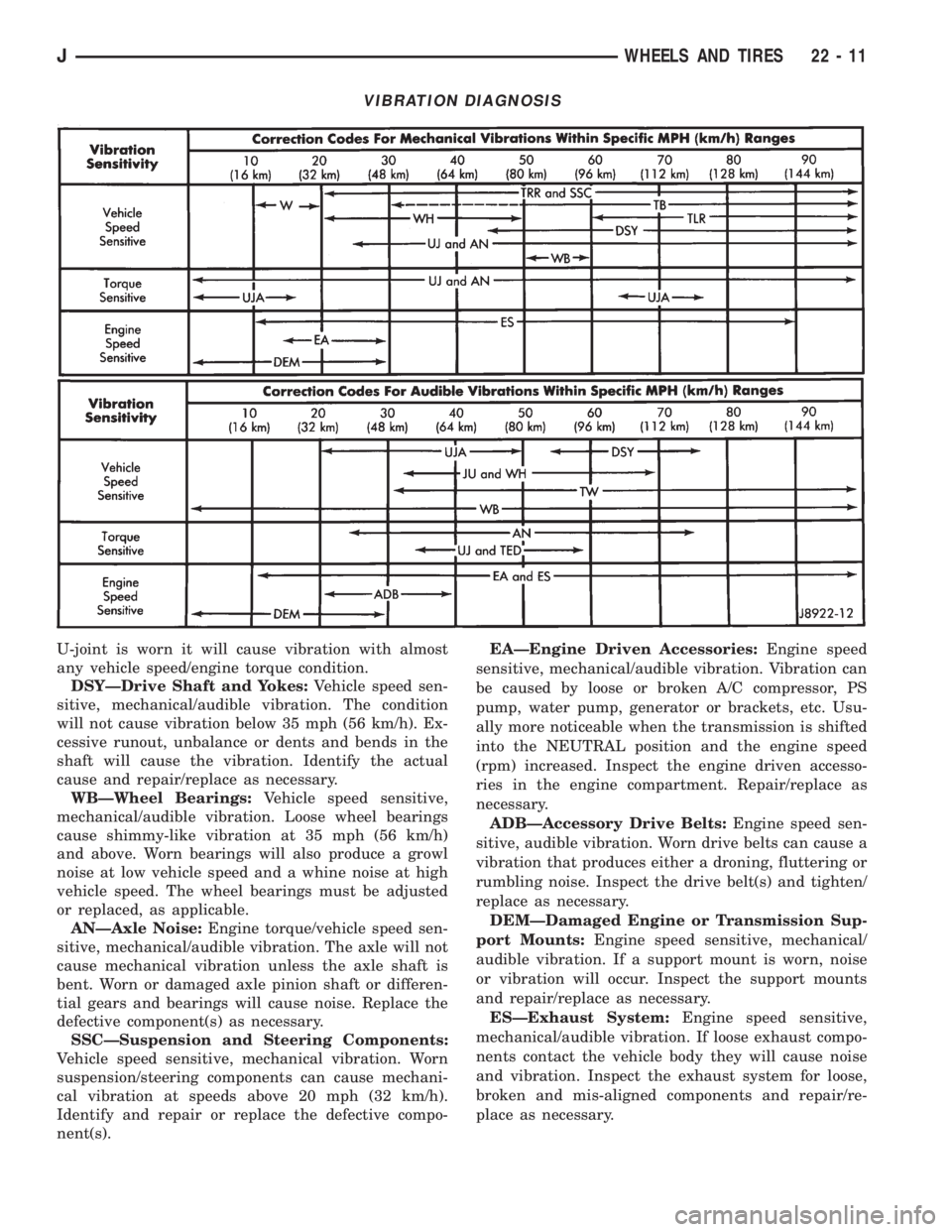
U-joint is worn it will cause vibration with almost
any vehicle speed/engine torque condition.
DSYÐDrive Shaft and Yokes:Vehicle speed sen-
sitive, mechanical/audible vibration. The condition
will not cause vibration below 35 mph (56 km/h). Ex-
cessive runout, unbalance or dents and bends in the
shaft will cause the vibration. Identify the actual
cause and repair/replace as necessary.
WBÐWheel Bearings:Vehicle speed sensitive,
mechanical/audible vibration. Loose wheel bearings
cause shimmy-like vibration at 35 mph (56 km/h)
and above. Worn bearings will also produce a growl
noise at low vehicle speed and a whine noise at high
vehicle speed. The wheel bearings must be adjusted
or replaced, as applicable.
ANÐAxle Noise:Engine torque/vehicle speed sen-
sitive, mechanical/audible vibration. The axle will not
cause mechanical vibration unless the axle shaft is
bent. Worn or damaged axle pinion shaft or differen-
tial gears and bearings will cause noise. Replace the
defective component(s) as necessary.
SSCÐSuspension and Steering Components:
Vehicle speed sensitive, mechanical vibration. Worn
suspension/steering components can cause mechani-
cal vibration at speeds above 20 mph (32 km/h).
Identify and repair or replace the defective compo-
nent(s).EAÐEngine Driven Accessories:Engine speed
sensitive, mechanical/audible vibration. Vibration can
be caused by loose or broken A/C compressor, PS
pump, water pump, generator or brackets, etc. Usu-
ally more noticeable when the transmission is shifted
into the NEUTRAL position and the engine speed
(rpm) increased. Inspect the engine driven accesso-
ries in the engine compartment. Repair/replace as
necessary.
ADBÐAccessory Drive Belts:Engine speed sen-
sitive, audible vibration. Worn drive belts can cause a
vibration that produces either a droning, fluttering or
rumbling noise. Inspect the drive belt(s) and tighten/
replace as necessary.
DEMÐDamaged Engine or Transmission Sup-
port Mounts:Engine speed sensitive, mechanical/
audible vibration. If a support mount is worn, noise
or vibration will occur. Inspect the support mounts
and repair/replace as necessary.
ESÐExhaust System:Engine speed sensitive,
mechanical/audible vibration. If loose exhaust compo-
nents contact the vehicle body they will cause noise
and vibration. Inspect the exhaust system for loose,
broken and mis-aligned components and repair/re-
place as necessary.
VIBRATION DIAGNOSIS
JWHEELS AND TIRES 22 - 11
Page 2131 of 2158
CYLINDER COMBUSTION PRESSURE
LEAKAGE TEST DIAGNOSIS..............9-7
CYLINDER COMPRESSION PRESSURE
TEST................................9-5
CYLINDER DISPOSALÐXJ, LIFTGATE
SUPPORT ROD......................23-63
CYLINDER ENGINE, VACUUM ROUTING
SCHEMATICÐ2.5L 4...................25-3
CYLINDER ENGINE, VACUUM ROUTING
SCHEMATICÐ4.0L 6...................25-3
CYLINDER HEAD COVER, ENGINE....9-22,9-64
CYLINDER HEAD, ENGINE...........9-25,9-67
CYLINDER HEAD GASKET FAILURE
DIAGNOSIS, ENGINE....................9-5
CYLINDER INSTALLATION (NON-ABS),
MASTER............................5-16
CYLINDER INSTALLATION, WHEEL........5-58
CYLINDER OVERHAUL (4-CYLINDER
MODELS), MASTER....................5-16
CYLINDER OVERHAUL, WHEEL...........5-57
CYLINDER REMOVAL (NON-ABS),
MASTER............................5-15
CYLINDER REMOVAL, WHEEL...........5-57
CYLINDER SERVICE, IGNITION SWITCH
AND KEY...........................8D-26
CYLINDERÐCOMBINATION VALVE,
MASTER............................5-15
CYLINDERÐXJ, DOOR KEY LOCK.......23-47
CYLINDERÐXJ, LIFTGATE SUPPORT
ROD...............................23-62
CYLINDERÐYJ, FULL-METAL DOOR KEY
LOCK..............................23-139
CYLINDERÐYJ, TAILGATE LOCK.......23-122
CYLINDER/POWER BOOSTER TEST,
MASTER.............................5-8
CYLINDER/POWER BRAKE BOOSTER,
MASTER............................5-34
CYLINDER/STRIKERÐXJ, LIFTGATE
LATCH/KEY LOCK....................23-61
DAMAGED OR WORN THREADS, REPAIR....9-4
DAMPER, ENGINE.....................9-17
DAMPER, STEERING.............19-17,19-20
DAMPER, VIBRATION..............9-30,9-72
DASH PANEL INSULATOR PANELÐXJ....23-12
DATA LINK CONNECTOR; ANTI-LOCK
BRAKES (XJ)......................8W-32-2
DATA LINK CONNECTOR; ANTI-LOCK
BRAKES (XJ-RHD).................8W-32-2
DATA LINK CONNECTOR; ANTI-LOCK
BRAKES (YJ)......................8W-32-2
DATA LINK CONNECTOR; FUEL/IGNITION
(XJ).............................8W-30-5
DATA LINK CONNECTOR; FUEL/IGNITION
(YJ).............................8W-30-5
DATA LINK CONNECTOR;
TRANSMISSION CONTROLS (XJ-RHD) . . 8W-31-1
DATA LINK CONNECTOR; FUEL/IGNITION
(XJ-RHD).........................8W-30-4
DATA LINK CONNECTORÐPCM INPUT....14-22
DATA LINK CONNECTORÐPCM OUTPUT . . 14-27
DATA, VEHICLE DIMENSION.....Intro.-5,Intro.-6
DATA, VEHICLE LOAD................Intro.-5
DATAÐXJ, VEHICLE LOAD............Intro.-7
DATAÐYJ, VEHICLE LOAD............Intro.-8
DAYTIME RUNNING LAMP (DRL)
MODULE; FRONT LIGHTING (XJ)......8W-50-2
DAYTIME RUNNING LAMP (DRL)
MODULEÐCANADIAN VEHICLES ONLY;
FRONT LIGHTING (YJ)
..............8W-50-2
DAYTIME RUNNING LIGHTS (CANADA
ONLY)ÐXJ
.........................8L-15
DAYTIME RUNNING LIGHTS (CANADA
ONLY)ÐYJ
.........................8L-30
DECODING, VEHICLE CODE
...........Intro.-5
DECODING, VEHICLE IDENTIFICATION
NUMBER (VIN)
.....................Intro.-4
DEFLECTORÐXJ, COWL WEATHERSTRIP
SEAL/CROSSMEMBER AIR
.............23-11
DEFOGGER RELAY
....................8N-3
DEFOGGER RELAY/TIMER
...............8N-1
DEFOGGER RELAY/TIMER REMOVE/
INSTALL
............................8N-4
DEFOGGER SWITCH
...............8N-1,8N-3
DEFOGGER SWITCH REMOVE/INSTALL
....8N-4
DEFROSTER NOZZLE AND DUCT
........24-33
DELAY FUNCTION TROUBLE
DIAGNOSISÐXJ, HEADLAMP
...........8L-14DELAY MODULE, HEADLAMP; FRONT
LIGHTING (XJ)....................8W-50-2
DELAY MODULE, HEADLAMP; FRONT
LIGHTING (XJ-RHD)................8W-50-1
DELAY MODULE REPLACEMENTÐXJ,
HEADLAMP.........................8L-14
DELAY MODULEÐXJ, SENTINEL
HEADLAMP.........................8L-14
DELIVERY SYSTEM, FUEL...............14-3
DEMAGNETIZING, COMPASS............8C-5
DEPTH INFORMATION, PINION GEAR;
FRONT SUSPENSION AND AXLE..........2-39
DEPTH INFORMATION, PINION GEAR;
REAR SUSPENSION AND AXLES..........3-21
DEPTH VARIANCE, PINION GEAR; FRONT
SUSPENSION AND AXLE................2-40
DEPTH VARIANCE, PINION GEAR; REAR
SUSPENSION AND AXLES...........3-22,3-39
DESCRIPTION; HEATING AND AIR
CONDITIONING............24-19,24-23,24-32
DESCRIPTION; TRANSMISSION AND
TRANSFER CASE....................21-165
DESCRIPTION/SYSTEM OPERATION,
MULTI-PORT FUEL INJECTION
(MFI)ÐCOMPONENT..................14-19
DESIGNATIONS, LABELS/PLATES, CODES
AND DIMENSIONS..................Intro.-1
DESIGNATIONS, VEHICLE.............Intro.-1
DESIGNATIONS, VEHICLE CODE........Intro.-1
DETECTION AND REPAIRÐXJ,
STATIONARY GLASS WATER LEAK.......23-76
DETECTION AND REPAIRÐYJ,
STATIONARY GLASS WATER LEAK.......23-150
DEVICES, ELECTROSTATIC DISCHARGE
(ESD) SENSITIVE; WIRING
DIAGRAMSÐGENERAL INFORMATION
(XJ)...............................8W-2
DIAGNOSING PARKING BRAKE
MALFUNCTIONS.......................5-8
DIAGNOSIS; AUDIO SYSTEMS...........8F-2
DIAGNOSIS; BATTERY/STARTING/
CHARGING SYSTEMS DIAGNOSTICS.....8A-10,
8A-11,8A-17,8A-3
DIAGNOSIS; CHIME/BUZZER WARNING
SYSTEMS...........................8U-2
DIAGNOSIS; COOLING SYSTEM...........7-4
DIAGNOSIS; HORNS...................8G-2
DIAGNOSIS; INSTRUMENT PANEL AND
GAUGESÐXJ....................8E-27,8E-5
DIAGNOSIS; OVERHEAD CONSOLE........8C-2
DIAGNOSIS; POWER LOCKS.............8P-2
DIAGNOSIS; POWER MIRRORS..........8T-1
DIAGNOSIS; POWER SEATS.............8R-2
DIAGNOSIS; POWER WINDOWS..........8S-1
DIAGNOSIS; REAR WINDOW DEFOGGER . . . 8N-1
DIAGNOSIS; RESTRAINT SYSTEMS.......8M-2
DIAGNOSIS; STEERING................19-37
DIAGNOSIS; TURN SIGNAL AND HAZARD
WARNING SYSTEMS...................8J-3
DIAGNOSIS; VEHICLE SPEED CONTROL
SYSTEM............................8H-2
DIAGNOSIS, 2.5L STARTER NOISE.......8A-16
DIAGNOSIS, 30RH/32RH TRANSMISSION . 21-70
DIAGNOSIS, ABS BRAKE.................5-3
DIAGNOSIS, ANTILOCK ECU AND HCU......5-3
DIAGNOSIS, AW-4 TRANSMISSION.....21-176
DIAGNOSIS, AXLE NOISE/VIBRATION;
FRONT SUSPENSION AND AXLE..........2-18
DIAGNOSIS, AXLE NOISE/VIBRATION;
REAR SUSPENSION AND AXLES..........3-9
DIAGNOSIS, BATTERY..................8A-4
DIAGNOSIS, BELT.....................7-38
DIAGNOSIS, CHARGING SYSTEM........8A-19
DIAGNOSIS, CLUTCH...................6-3
DIAGNOSIS, COMPASS/THERMOMETER....8C-4
DIAGNOSIS (CONT.), COOLING SYSTEM . . . 7-10,
7-11,7-12,7-7,7-8,7-9
DIAGNOSIS (CONT.), SERPENTINE DRIVE
BELT ...............................7-40
DIAGNOSIS (CONT'D), DISCONNECT
AXLE/SHIFT MOTOR
...................2-30
DIAGNOSIS (CONT'D), SERVICE; FRONT
SUSPENSION AND AXLE
................2-21
DIAGNOSIS (CONT'D), SERVICE; REAR
SUSPENSION AND AXLES
...............3-12
DIAGNOSIS, CONVERTER HOUSING
LEAK
..............................21-75
DIAGNOSIS, COOLING SYSTEM
...........7-6DIAGNOSIS, CYLINDER COMBUSTION
PRESSURE LEAKAGE TEST...............9-7
DIAGNOSIS, DISCONNECT AXLE/SHIFT
MOTOR.............................2-29
DIAGNOSIS, ENGINE....................9-5
DIAGNOSIS, ENGINE CYLINDER HEAD
GASKET FAILURE......................9-5
DIAGNOSIS, EXHAUST SYSTEM..........11-2
DIAGNOSIS, FOG LAMP...........8L-21,8L-3
DIAGNOSIS, GEAR LEAKAGE............19-10
DIAGNOSIS, HEADLAMP...........8L-20,8L-2
DIAGNOSIS, HEATER..................24-17
DIAGNOSIS, HEATING SYSTEM..........24-18
DIAGNOSIS, IGNITION SECONDARY
CIRCUIT...........................8D-10
DIAGNOSIS INFORMATION, GENERAL;
CLUTCH..............................6-3
DIAGNOSIS INFORMATION, GENERAL;
TRANSMISSION AND TRANSFER CASE . . 21-176
DIAGNOSIS, INTAKE MANIFOLD
LEAKAGE.............................9-5
DIAGNOSIS, MANUAL STEERING
SYSTEM............................19-38
DIAGNOSIS, MULTI-PORT FUEL
INJECTION (MFI)ÐGENERAL...........14-35
DIAGNOSIS, NP231 SERVICE..........21-285
DIAGNOSIS, NP242 SERVICE..........21-308
DIAGNOSIS, PERFORMANCE............24-14
DIAGNOSIS, POWER STEERING SYSTEM . . 19-3,
19-4,19-5,19-6,19-7,19-8,19-9
DIAGNOSIS, PUMP LEAKAGE...........19-10
DIAGNOSIS, RADIO....................8F-3
DIAGNOSIS, SERPENTINE DRIVE BELT.....7-39
DIAGNOSIS, SERVICE; FRONT
SUSPENSION AND AXLE................2-20
DIAGNOSIS, SERVICE; PROPELLER
SHAFTS.............................16-3
DIAGNOSIS, SERVICE; REAR
SUSPENSION AND AXLES...............3-11
DIAGNOSIS, SERVICE; TRANSMISSION
AND TRANSFER CASE . 21-180,21-181,21-34,21-2
DIAGNOSIS, SERVICE BRAKE.............5-4
DIAGNOSIS, SPRING AND SHOCK;
FRONT SUSPENSION AND AXLE......2-13,2-15
DIAGNOSIS, SPRING AND SHOCK; REAR
SUSPENSION AND AXLES.............3-3,3-6
DIAGNOSIS, SPRING AND SHOCK
ABSORBER........................3-3,3-6
DIAGNOSIS, STARTER NOISE...........8A-16
DIAGNOSIS, STARTING SYSTEM........8A-12
DIAGNOSIS, SUSPENSION AND
STEERING SYSTEM.....................2-7
DIAGNOSIS, THERMOMETER............8C-2
DIAGNOSIS, TORQUE CONVERTER . 21-86,21-87,
21-88
DIAGNOSIS, TRANSMISSION . 21-78,21-79,21-80,
21-81,21-82,21-83,21-84,21-85
DIAGNOSIS, VIBRATION..........22-10,22-11
DIAGNOSISÐLUBRICATION SERVICE......9-12
DIAGNOSISÐXJ, DOME/COURTESY
LAMP TROUBLE.....................8L-16
DIAGNOSISÐXJ, HEADLAMP DELAY
FUNCTION TROUBLE..................8L-14
DIAGNOSISÐXJ, LIGHTED VANITY
MIRROR TROUBLE...................8L-16
DIAGNOSISÐYJ, DOME/COURTESY
LAMP TROUBLE.....................8L-31
DIAGNOSTIC CONNECTOR, ABS.......5-35,5-3
DIAGNOSTIC PROCEDURESÐXJ.........8L-1
DIAGNOSTIC PROCEDURESÐYJ........8L-19
DIAGNOSTIC SYSTEM, USING
ON-BOARD; BATTERY/STARTING/
CHARGING SYSTEMS DIAGNOSTICS.....8A-22
DIAGNOSTIC SYSTEM, USING
ON-BOARD; VEHICLE SPEED CONTROL
SYSTEM............................8H-5
DIAGNOSTIC TROUBLE CODE (DTC)......14-54
DIAGNOSTIC TROUBLE CODE,
GENERATOR........................8A-22
DIAGNOSTIC TROUBLE CODE, SPEED
CONTROL
...........................8H-5
DIAGNOSTICS (OBD), ON-BOARD;
COOLING SYSTEM
.....................7-4
DIAGNOSTICS (OBD), ON-BOARD; FUEL
SYSTEM
............................14-51
DIAGNOSTICS, ON-BOARD
.............8D-15
DIAGRAM INDEX; AIR CONDITIONING/
HEATER (XJ)
......................8W-42-2
JINDEX 7
Description Group-Page Description Group-Page Description Group-Page