1995 JEEP YJ mirror
[x] Cancel search: mirrorPage 2022 of 2158
EXTERIOR COMPONENTS
INDEX
page page
Battery TrayÐYJ......................... 110
Body Side Step MoldingÐYJ................ 115
Body Stripes/DecalsÐYJ................... 116
Cowl Grille and ScreenÐYJ................ 109
Cowl Weatherstrip SealÐYJ................ 109
Exterior Nameplates (Adhesive-Backed)ÐYJ.... 120
External Spare/Wheel Tire CarrierÐYJ........ 133
Fender FlareÐYJ........................ 114
Fender Inner Splash ShieldsÐYJ............. 116
Fender Splash ApronsÐYJ................. 115
FendersÐYJ............................ 110
Fuel Filler Protector/NozzleÐYJ............. 121
Half Metal Door Mirror (External)ÐYJ......... 121
Hard Top Liftgate GlassÐYJ................ 124
Hard Top RepairÐYJ..................... 127
Hard Top Roof VentÐYJ................... 127
Hard TopÐYJ........................... 126Hood AlignmentÐYJ...................... 107
Hood Insulator PanelÐYJ.................. 107
Hood Safety LatchÐYJ.................... 109
HoodÐYJ.............................. 107
Liftgate Glass Weatherstrip Seal ReplacementÐYJ. 125
Radiator Grille AppliqueÐYJ................ 104
Soft Top Service InformationÐYJ............. 127
Soft Top ServiceÐYJ..................... 129
Sport BarÐYJ........................... 132
Tailgate AdjustmentÐYJ................... 121
Tailgate HingeÐYJ....................... 121
Tailgate Latch and Release HandleÐYJ........ 122
Tailgate Latch StrikerÐYJ.................. 123
Tailgate Lock CylinderÐYJ................. 122
Tailgate Weatherstrip SealÐYJ.............. 123
TailgateÐYJ............................ 121
Wheelhouse Splash LinersÐYJ.............. 115
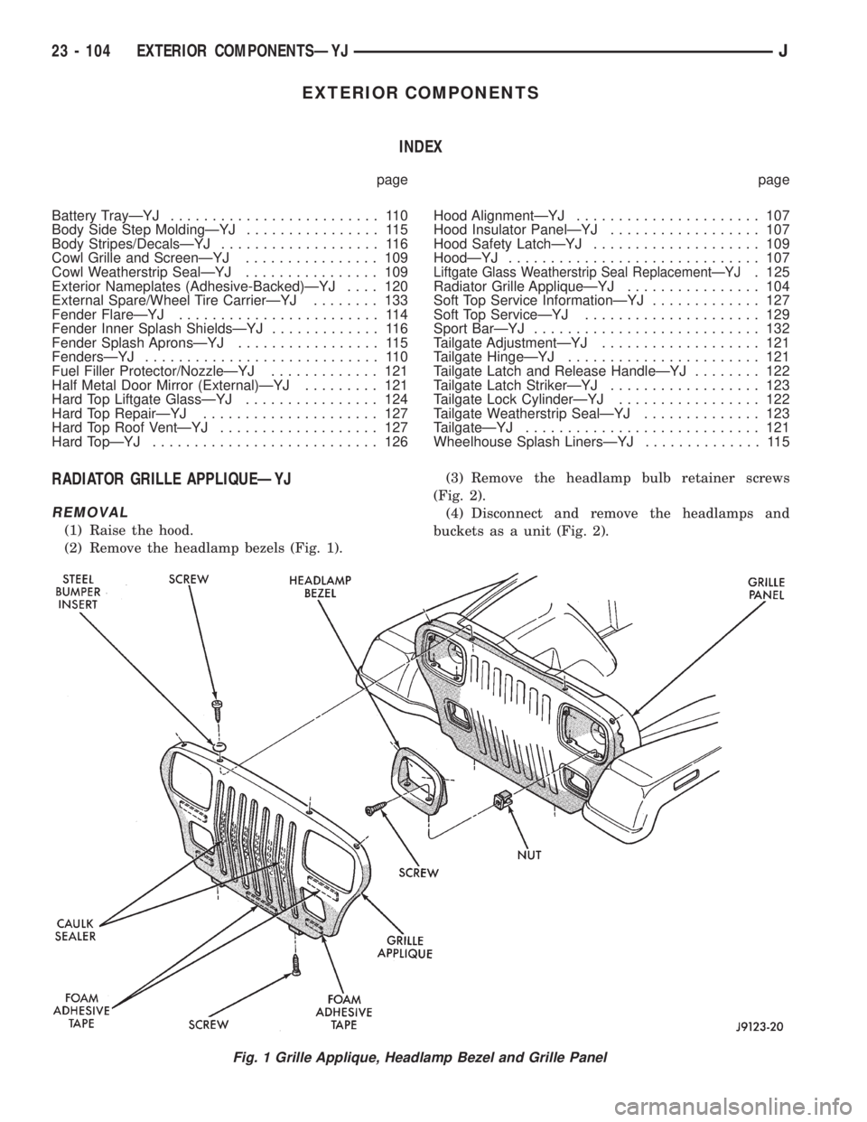
RADIATOR GRILLE APPLIQUEÐYJ
REMOVAL
(1) Raise the hood.
(2) Remove the headlamp bezels (Fig. 1).(3) Remove the headlamp bulb retainer screws
(Fig. 2).
(4) Disconnect and remove the headlamps and
buckets as a unit (Fig. 2).
Fig. 1 Grille Applique, Headlamp Bezel and Grille Panel
23 - 104 EXTERIOR COMPONENTSÐYJJ
Page 2039 of 2158
(3) Position the replacement nameplate on the
panel and apply inward force to seat it.
FUEL FILLER PROTECTOR/NOZZLEÐYJ
REMOVAL
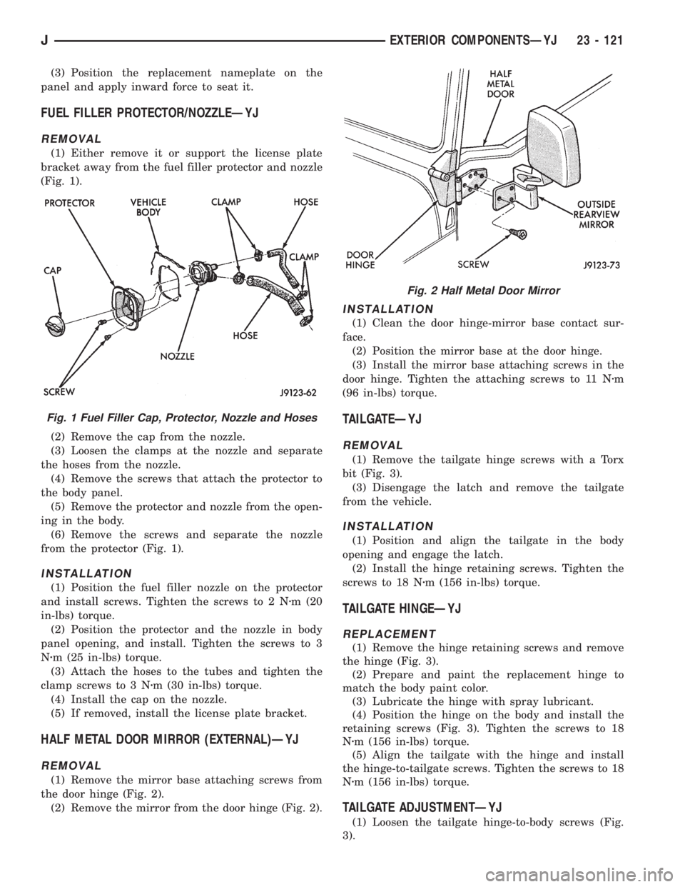
(1) Either remove it or support the license plate
bracket away from the fuel filler protector and nozzle
(Fig. 1).
(2) Remove the cap from the nozzle.
(3) Loosen the clamps at the nozzle and separate
the hoses from the nozzle.
(4) Remove the screws that attach the protector to
the body panel.
(5) Remove the protector and nozzle from the open-
ing in the body.
(6) Remove the screws and separate the nozzle
from the protector (Fig. 1).
INSTALLATION
(1) Position the fuel filler nozzle on the protector
and install screws. Tighten the screws to 2 Nzm (20
in-lbs) torque.
(2) Position the protector and the nozzle in body
panel opening, and install. Tighten the screws to 3
Nzm (25 in-lbs) torque.
(3) Attach the hoses to the tubes and tighten the
clamp screws to 3 Nzm (30 in-lbs) torque.
(4) Install the cap on the nozzle.
(5) If removed, install the license plate bracket.
HALF METAL DOOR MIRROR (EXTERNAL)ÐYJ
REMOVAL
(1) Remove the mirror base attaching screws from
the door hinge (Fig. 2).
(2) Remove the mirror from the door hinge (Fig. 2).
INSTALLATION
(1) Clean the door hinge-mirror base contact sur-
face.
(2) Position the mirror base at the door hinge.
(3) Install the mirror base attaching screws in the
door hinge. Tighten the attaching screws to 11 Nzm
(96 in-lbs) torque.
TAILGATEÐYJ
REMOVAL
(1) Remove the tailgate hinge screws with a Torx
bit (Fig. 3).
(3) Disengage the latch and remove the tailgate
from the vehicle.
INSTALLATION
(1) Position and align the tailgate in the body
opening and engage the latch.
(2) Install the hinge retaining screws. Tighten the
screws to 18 Nzm (156 in-lbs) torque.
TAILGATE HINGEÐYJ
REPLACEMENT
(1) Remove the hinge retaining screws and remove
the hinge (Fig. 3).
(2) Prepare and paint the replacement hinge to
match the body paint color.
(3) Lubricate the hinge with spray lubricant.
(4) Position the hinge on the body and install the
retaining screws (Fig. 3). Tighten the screws to 18
Nzm (156 in-lbs) torque.
(5) Align the tailgate with the hinge and install
the hinge-to-tailgate screws. Tighten the screws to 18
Nzm (156 in-lbs) torque.
TAILGATE ADJUSTMENTÐYJ
(1) Loosen the tailgate hinge-to-body screws (Fig.
3).
Fig. 1 Fuel Filler Cap, Protector, Nozzle and Hoses
Fig. 2 Half Metal Door Mirror
JEXTERIOR COMPONENTSÐYJ 23 - 121
Page 2062 of 2158
STATIONARY GLASS
INDEX
page page
Hard Top Quarter Window GlassÐYJ......... 149
Rearview Mirror Retaining BracketÐYJ........ 144
Rearview MirrorÐYJ...................... 144
Stationary Glass Water Leak Detection and
RepairÐYJ........................... 150Windshield Frame Weatherstrip SealÐYJ...... 146
Windshield FrameÐYJ.................... 145
Windshield GlassÐYJ..................... 146
Windshield Reveal MoldingÐYJ............. 144
WINDSHIELD REVEAL MOLDINGÐYJ
REMOVAL
(1) Disengage the reveal molding around the pe-
rimeter of the windshield glass with an appropriate
tool.
(2) Remove the moldings from the windshield
frame.
(3) Inspect the reveal molding retainers. Replace
the molding if it has broken, distorted or ineffective
retainers.
INSTALLATION
(1) Position the reveal moldings on the windshield
frame.
(2) Attach the moldings to the frame by tapping
each molding with a rubber mallet to seat the retain-
ers.
REARVIEW MIRRORÐYJ
REMOVAL/INSTALLATION
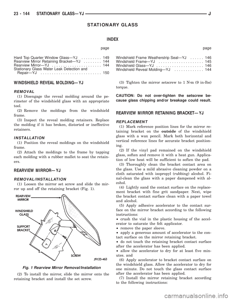
(1) Loosen the mirror set screw and slide the mir-
ror up and off the retaining bracket (Fig. 1).
(2) To install the mirror, slide the mirror onto the
retaining bracket and install the set screw.(3) Tighten the mirror setscrew to 1 Nzm (9 in-lbs)
torque.
CAUTION: Do not over-tighten the setscrew be-
cause glass chipping and/or breakage could result.
REARVIEW MIRROR RETAINING BRACKETÐYJ
REPLACEMENT
(1) Mark reference position lines for the mirror re-
taining bracket on theoutsideof the windshield
glass with a wax pencil. Mark both horizontal and
vertical reference lines for accurate bracket position-
ing.
(2) If the vinyl pad remained on the windshield
glass, soften and remove it with a heat gun. Applica-
tion of low heat will be sufficient to soften the pad.
(3) Thoroughly clean the bracket contact area on
the glass. Use a mild abrasive cleaning powder on a
cloth saturated with isopropyl (rubbing) alcohol. Fi-
nal-clean the glass with a paper dampened with al-
cohol.
(4) Lightly sand the contact surface on the replace-
ment bracket with fine grit sandpaper. Next, wipe
the bracket contact surface clean with a paper towel
and alcohol.
(5) Apply adhesive accelerator to the contact sur-
face on the mirror bracket according to the following
instructions:
²crush the vial in the plastic housing of the accel-
erator to saturate the felt applicator.
²remove the paper sleeve.
²apply a generous amount of accelerator to the con-
tact surface on the mirror retaining bracket.
²do not touch the retaining bracket contact surface
after the accelerator has been applied.
²allow the accelerator to dry for at least five min-
utes. and
(6) Apply accelerator to bracket contact surface on
the windshield glass. Allow the accelerator to dry for
one minute. Do not touch the glass contact surface
after the accelerator has been applied.
(7) Install the mirror retaining bracket according
to the following instructions:
Fig. 1 Rearview Mirror Removal/Installation
23 - 144 STATIONARY GLASSÐYJJ
Page 2063 of 2158
²Apply one drop of adhesive at the center of the re-
taining bracket contact surface on the windshield
glass.
²Immediately apply an even coat of adhesive to the
contact surface on the retaining bracket.
²Align the retaining bracket with the position refer-
ence lines on the windshield glass.
²Press and hold the retaining bracket in-place for
at least one minute.
Ensure that the mirror retaining bracket is
correctly aligned because the adhesive will
cure rapidly.
(8) Allow the adhesive to cure for 8-10 minutes,
then remove any residue adhesive with an alcohol
dampened cloth.
(9) Allow the adhesive to cure for an additional
8-10 minutes before installing the mirror on the re-
taining bracket (Fig. 1).
WINDSHIELD FRAMEÐYJ
SERVICE INFORMATION
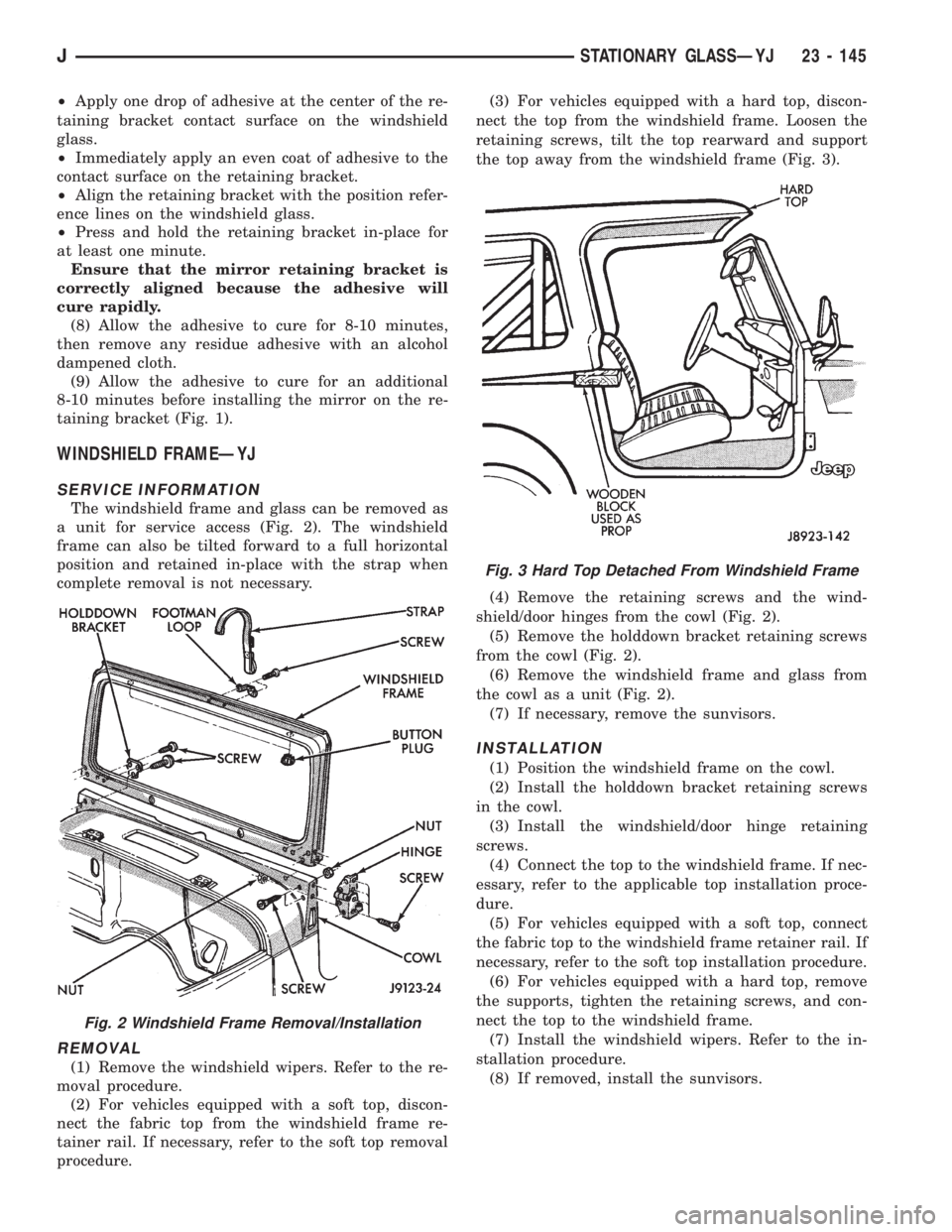
The windshield frame and glass can be removed as
a unit for service access (Fig. 2). The windshield
frame can also be tilted forward to a full horizontal
position and retained in-place with the strap when
complete removal is not necessary.
REMOVAL
(1) Remove the windshield wipers. Refer to the re-
moval procedure.
(2) For vehicles equipped with a soft top, discon-
nect the fabric top from the windshield frame re-
tainer rail. If necessary, refer to the soft top removal
procedure.(3) For vehicles equipped with a hard top, discon-
nect the top from the windshield frame. Loosen the
retaining screws, tilt the top rearward and support
the top away from the windshield frame (Fig. 3).
(4) Remove the retaining screws and the wind-
shield/door hinges from the cowl (Fig. 2).
(5) Remove the holddown bracket retaining screws
from the cowl (Fig. 2).
(6) Remove the windshield frame and glass from
the cowl as a unit (Fig. 2).
(7) If necessary, remove the sunvisors.
INSTALLATION
(1) Position the windshield frame on the cowl.
(2) Install the holddown bracket retaining screws
in the cowl.
(3) Install the windshield/door hinge retaining
screws.
(4) Connect the top to the windshield frame. If nec-
essary, refer to the applicable top installation proce-
dure.
(5) For vehicles equipped with a soft top, connect
the fabric top to the windshield frame retainer rail. If
necessary, refer to the soft top installation procedure.
(6) For vehicles equipped with a hard top, remove
the supports, tighten the retaining screws, and con-
nect the top to the windshield frame.
(7) Install the windshield wipers. Refer to the in-
stallation procedure.
(8) If removed, install the sunvisors.
Fig. 2 Windshield Frame Removal/Installation
Fig. 3 Hard Top Detached From Windshield Frame
JSTATIONARY GLASSÐYJ 23 - 145
Page 2064 of 2158
WINDSHIELD FRAME WEATHERSTRIP SEALÐYJ
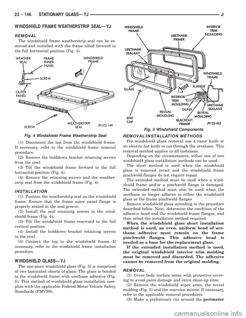
REMOVAL
The windshield frame weatherstrip seal can be re-
moved and installed with the frame tilted forward to
the full horizontal position (Fig. 4).
(1) Disconnect the top from the windshield frame.
If necessary, refer to the windshield frame removal
procedure.
(2) Remove the holddown bracket retaining screws
from the cowl.
(3) Tilt the windshield frame forward to the full
horizontal position (Fig. 4).
(4) Remove the retaining screws and the weather-
strip seal from the windshield frame (Fig. 4).
INSTALLATION
(1) Position the weatherstrip seal on the windshield
frame. Ensure that the frame outer panel flange is
properly seated in the seal groove.
(2) Install the seal retaining screws in the wind-
shield frame (Fig. 4).
(3) Tilt the windshield frame rearward to the full
vertical position.
(4) Install the holddown bracket retaining screws
in the cowl.
(5) Connect the top to the windshield frame. If
necessary, refer to the windshield frame installation
procedure.
WINDSHIELD GLASSÐYJ
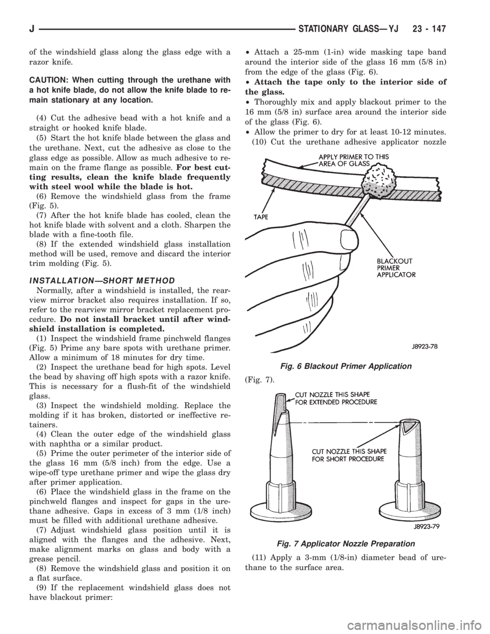
The one-piece windshield glass (Fig. 5) is comprised
of two laminated sheets of glass. The glass is bonded
to the windshield frame with urethane adhesive (Fig.
5). This method of windshield glass installation com-
plies with the applicable Federal Motor Vehicle Safety
Standards (FMVSS).
REMOVAL/INSTALLATION METHODS
For windshield glass removal use a razor knife or
an electric hot knife to cut through the urethane. This
removal method applies in all instances.
Depending on the circumstances, either one of two
windshield glass installation methods can be used.
The short method is used when the windshield
glass is removed intact and the windshield frame
pinchweld flanges do not require repair.
The extended method must be used when a wind-
shield frame and/or a pinchweld flange is damaged.
The extended method must also be used when the
urethane no longer adheres to either the windshield
glass or the frame pinchweld flanges.
Remove windshield glass according to the procedure
described below. Next, determine the condition of the
adhesive bond and the windshield frame flanges, and
then select the installation method required.
When the windshield glass short installation
method is used, an even, uniform bead of ure-
thane adhesive must remain on the frame
pinchweld flanges. This adhesive bead is
needed as a base for the replacement glass.
If the extended installation method is used,
the original windshield interior trim molding
must be removed and discarded. The adhesive
cannot be removed from the original molding.
REMOVAL
(1) Cover body surface areas with protective cover-
ing to avoid paint damage and extra clean-up time.
(2) Remove the windshield wiper arms, the reveal
molding (Fig. 5) and the rearview mirror. If necessary,
refer to the applicable removal procedures.
(3) Make a preliminary cut around theperimeter
Fig. 4 Windshield Frame Weatherstrip Seal
Fig. 5 Windshield Components
23 - 146 STATIONARY GLASSÐYJJ
Page 2065 of 2158
of the windshield glass along the glass edge with a
razor knife.
CAUTION: When cutting through the urethane with
a hot knife blade, do not allow the knife blade to re-
main stationary at any location.
(4) Cut the adhesive bead with a hot knife and a
straight or hooked knife blade.
(5) Start the hot knife blade between the glass and
the urethane. Next, cut the adhesive as close to the
glass edge as possible. Allow as much adhesive to re-
main on the frame flange as possible.For best cut-
ting results, clean the knife blade frequently
with steel wool while the blade is hot.
(6) Remove the windshield glass from the frame
(Fig. 5).
(7) After the hot knife blade has cooled, clean the
hot knife blade with solvent and a cloth. Sharpen the
blade with a fine-tooth file.
(8) If the extended windshield glass installation
method will be used, remove and discard the interior
trim molding (Fig. 5).
INSTALLATIONÐSHORT METHOD
Normally, after a windshield is installed, the rear-
view mirror bracket also requires installation. If so,
refer to the rearview mirror bracket replacement pro-
cedure.Do not install bracket until after wind-
shield installation is completed.
(1) Inspect the windshield frame pinchweld flanges
(Fig. 5) Prime any bare spots with urethane primer.
Allow a minimum of 18 minutes for dry time.
(2) Inspect the urethane bead for high spots. Level
the bead by shaving off high spots with a razor knife.
This is necessary for a flush-fit of the windshield
glass.
(3) Inspect the windshield molding. Replace the
molding if it has broken, distorted or ineffective re-
tainers.
(4) Clean the outer edge of the windshield glass
with naphtha or a similar product.
(5) Prime the outer perimeter of the interior side of
the glass 16 mm (5/8 inch) from the edge. Use a
wipe-off type urethane primer and wipe the glass dry
after primer application.
(6) Place the windshield glass in the frame on the
pinchweld flanges and inspect for gaps in the ure-
thane adhesive. Gaps in excess of 3 mm (1/8 inch)
must be filled with additional urethane adhesive.
(7) Adjust windshield glass position until it is
aligned with the flanges and the adhesive. Next,
make alignment marks on glass and body with a
grease pencil.
(8) Remove the windshield glass and position it on
a flat surface.
(9) If the replacement windshield glass does not
have blackout primer:²Attach a 25-mm (1-in) wide masking tape band
around the interior side of the glass 16 mm (5/8 in)
from the edge of the glass (Fig. 6).
²Attach the tape only to the interior side of
the glass.
²Thoroughly mix and apply blackout primer to the
16 mm (5/8 in) surface area around the interior side
of the glass (Fig. 6).
²Allow the primer to dry for at least 10-12 minutes.
(10) Cut the urethane adhesive applicator nozzle
(Fig. 7).
(11) Apply a 3-mm (1/8-in) diameter bead of ure-
thane to the surface area.
Fig. 6 Blackout Primer Application
Fig. 7 Applicator Nozzle Preparation
JSTATIONARY GLASSÐYJ 23 - 147
Page 2066 of 2158
CAUTION: Be prepared to install the windshield
glass immediately after applying the adhesive. The
adhesive begins to cure within 10-15 minutes.
(12) Align the windshield with the grease pencil
marks (or the tape strips) and position windshield on
frame flanges.
(13) Force the windshield glass inward just enough
to wet-out and set urethane. Use care to avoid exces-
sive squeeze-out of adhesive.
(14) Water test the windshield with a cold water
spray after installation. Do not direct high pressure
streams of water directly at the urethane. Use a
moderate spray only. If any leaks are detected, apply
urethane as necessary.
(15) Install the windshield reveal molding and (if
used) remove the masking tape from the inner sur-
face of the glass.
(16) Install all removed components and clean the
vehicle. If necessary, refer to the applicable installa-
tion procedures.
(17) Open windows and liftgate to prevent pres-
sure build-up while the urethane is curing.
(18) Install the rearview mirror on the bracket and
tighten the mirror setscrew with 2 Nzm (15 in-lbs)
torque.
INSTALLATIONÐEXTENDED METHOD
Normally, after a windshield is installed, the rear-
view mirror bracket also requires installation.Do
not install the bracket until after the wind-
shield installation is completed.
(1) Remove all of the original urethane from all the
frame pinchweld flanges. Use an electric hot knife
and a plow-type knife blade to remove the adhesive.
(2) Inspect and repair the windshield frame and
the pinchweld flanges as necessary.
(3) Inspect and replace the reveal molding if the
retainers are damaged.
(4) Prime the frame pinchweld flanges with a ure-
thane base primer. However, if the flange is top-
coated with paint, prime the flanges with a paint
finish primer.This is important because ure-
thane adhesive will not adhere to all top coat
paints.
(5) Install the replacement interior trim molding
(Fig. 5) on the frame pinchweld flanges (Fig. 5).
(6) Install and inspect the fit of the windshield
glass on the pinchweld flanges according to the fol-
lowing instructions:
²Position the windshield glass on the flanges and
adjust the position until it is correctly aligned within
the windshield frame.
²Measure the gap between the frame and the glass
around the entire perimeter of the glass and the
flange.
²The gap should be at least 3 mm (1/8 in) but no
more than 6 mm (1/4 in) at any point around the pe-rimeter, and the flanges should be in complete con-
tact with the glass around the perimeter of the
frame.
(7) If the pinchweld flanges require repair, remove
the windshield glass and straighten, align, or repair
the flange(s) as necessary.
(8) Position the windshield on the flanges and in-
spect the windshield fit again. If the fit is acceptable,
mark windshield final position on the glass and the
frame. The marks (or masking tape) will be used for
installation alignment reference.
(9) If the replacement windshield glass does not
have blackout primer:
²Attach a 25-mm (1-in) wide masking tape band
around the interior side of the glass 16 mm (5/8 in)
from the edge of the glass (Fig. 6).
²Attach the tape only to the interior side of
the glass.
²Thoroughly mix and apply blackout primer to the
16 mm (5/8 in) surface area around the interior side
of the glass (Fig. 6).
²Allow the primer to dry for at least 10-12 minutes.
(10) Cut the urethane adhesive applicator nozzle
(Fig. 7).
(11) Apply a 3-mm (1/8-in) diameter bead of ure-
thane to the surface area.
CAUTION: Be prepared to install the windshield
glass immediately after applying the adhesive. The
adhesive begins to cure within 10-15 minutes.
(12) Align windshield with reference marks (or the
tape strips) and position it on the frame pinchweld
flanges.
(13) Force the windshield glass inward just enough
to wet-out and set urethane. Use care to avoid exces-
sive squeeze-out of adhesive.
(14) Water test the windshield with a cold water
spray after installation. Do not direct high pressure
streams of water directly at the urethane. Use a
moderate spray only. If any leaks are detected, apply
urethane as necessary.
(15) Install the windshield reveal molding and (if
used) remove the masking tape from the inner sur-
face of the glass.
(16) Install all the other previously removed com-
ponents and clean the vehicle. If necessary, refer to
the applicable installation procedures.
(17) Open windows and liftgate to prevent pres-
sure build-up while the urethane is curing.
(18) Install the rearview mirror on the bracket and
tighten the mirror setscrew to 2 Nzm (15 in-lbs)
torque.
23 - 148 STATIONARY GLASSÐYJJ
Page 2127 of 2158
BELT TENSIONERÐXJ MODELS WITH
RIGHT HAND DRIVE, AUTOMATIC........7-42
BELT TENSIONÐEXCEPT RIGHT HAND
DRIVE (RHD).........................7-38
BELT TENSIONÐEXCEPT RIGHT HAND
DRIVE (RHD) MODELS.................7-45
BELT TENSIONÐRIGHT HAND DRIVE
(RHD)..............................7-38
BELT/BUCKLEÐXJ, FRONT SHOULDER . . . 23-90
BELT/BUCKLEÐXJ, REAR SHOULDER/
LAP ...............................23-91
BELTLINE SEALÐYJ.................23-142
BELTS, ENGINE ACCESSORY DRIVE.......7-38
BELTSÐYJ, FRONT SHOULDER........23-154
BELTSÐYJ, REAR SHOULDER.........23-154
BENCH BLEEDING, MASTER CYLINDER....5-21
BENCH, GEAR ADJUSTMENTS ON.......19-44
BENCH SEATÐYJ, REAR..............23-153
BEZELÐXJ, INSTRUMENT CLUSTER.....23-80
BEZELÐYJ, INSTRUMENT CLUSTER....23-151
BIN REMOVE/INSTALL, SUNGLASSES
STORAGE...........................8C-7
BLADE REMOVE/INSTALL, WINDSHIELD
WIPER.............................8K-17
BLEEDING, MASTER CYLINDER BENCH....5-21
BLEEDING RECOMMENDATIONS, BRAKE . . . 5-10
BLEEDING (WITH ABS BRAKES), BRAKE . . . 5-11
BLEEDING (WITH STANDARD BRAKES),
BRAKE..............................5-11
BLEEDINGÐBRAKELINES AND HOSES,
BRAKE FLUIDÐBRAKE.................5-10
BLOCK, CYLINDER................9-49,9-91
BLOCK HEATER, ENGINE................7-44
BLOCKSÐTWO-DOOR VEHICLES, FRONT
DOOR SPACER......................23-53
BLOWER MOTOR; AIR CONDITIONING/
HEATER (XJ)......................8W-42-1
BLOWER MOTOR; AIR CONDITIONING/
HEATER (XJ-RHD)..................8W-42-1
BLOWER MOTOR; HEATING AND AIR
CONDITIONING......................24-17
BLOWER MOTOR, A/C.................24-35
BLOWER MOTOR, A/C-HEATER; AIR
CONDITIONING/HEATER (YJ).........8W-42-2
BLOWER MOTOR (HEATING)...........24-33
BLOWER MOTOR RESISTORS
REPLACEMENT......................24-31
BLOWER MOTOR SWITCH.............24-16
BLOWER MOTOR/AIR DOOR MOTOR
SWITCH REPLACEMENT...............24-32
BLOWER MOTOR/FAN REPLACEMENT....24-24
BODY ASSEMBLY AND ADJUSTMENT,
VALVE ............................21-153
BODY CHECK BALL DIMENSIONS, AW-4
VALVE ............................21-341
BODY CODE LETTERS, JEEP..............5-2
BODY LUBRICANT SPECIFICATIONS.......0-33
BODY OVERHAUL, TRANSMISSION
VALVE ............................21-250
BODY REMOVAL, TRANSMISSION VALVE . 21-186
BODY REMOVAL, VALVE..............21-104
BODY SERVICE INFORMATION, GENERAL . . 23-1
BODY SERVICE, VALVE...............21-104
BODY SIDE MOLDING/CLADDINGÐXJ....23-20
BODY SIDE STEP MOLDINGÐYJ.......23-115
BODY SOLENOIDS, TRANSMISSION
VALVE ............................21-184
BODY STRIPES/DECALSÐXJ...........23-21
BODY STRIPES/DECALSÐYJ..........23-116
BODY, THROTTLE...............14-33,14-64
BOLT IDENTIFICATION..............Intro.-14
BOLT STRENGTH..................Intro.-15
BOOSTER CHECK VALVE TEST, POWER.....5-9
BOOSTER INSTALLATION (XJ WITH
ABS), POWER BRAKE..................5-27
BOOSTER INSTALLATION (XJ WITHOUT
ABS), POWER BRAKE..................5-30
BOOSTER INSTALLATION (YJ), POWER
BRAKE..............................5-30
BOOSTER, MASTER CYLINDER/POWER
BRAKE
..............................5-34
BOOSTER OPERATION, POWER BRAKE
....5-23
BOOSTER REMOVAL (XJ WITH ABS),
POWER BRAKE
.......................5-24
BOOSTER REMOVAL (XJ WITHOUT ABS),
POWER BRAKE
.......................5-29
BOOSTER REMOVAL (YJ), POWER
BRAKE
..............................5-30BOOSTER TEST, MASTER CYLINDER/
POWER..............................5-8
BOOSTER VACUUM TEST, POWER.........5-9
BOOSTERÐBRAKE PEDALÐ
BRAKELIGHT SWITCH, POWER BRAKE....5-22
BORES, HONING CYLINDER..............9-2
BOX LAMP, GLOVE; INTERIOR LIGHTING
(XJ).............................8W-44-1
BOX LAMP, GLOVE; INTERIOR LIGHTING
(XJ-RHD).........................8W-44-1
BOXÐYJ, GLOVE...................23-152
BRACKET REPLACEMENTÐXJ, INTERIOR
REARVIEW MIRROR SUPPORT..........23-68
BRACKETÐYJ, REARVIEW MIRROR
RETAINING........................23-144
BRACKETSÐXJ, SPARE TIRE/WHEEL
HOLDDOWN AND FLOOR..............23-98
BRAKE ADJUSTMENT, DRUM............5-57
BRAKE BLEEDING RECOMMENDATIONS....5-10
BRAKE BLEEDING (WITH ABS BRAKES)....5-11
BRAKE BLEEDING (WITH STANDARD
BRAKES)............................5-11
BRAKE BOOSTER INSTALLATION (XJ
WITH ABS), POWER...................5-27
BRAKE BOOSTER INSTALLATION (XJ
WITHOUT ABS), POWER................5-30
BRAKE BOOSTER INSTALLATION (YJ),
POWER.............................5-30
BRAKE BOOSTER, MASTER CYLINDER/
POWER.............................5-34
BRAKE BOOSTER OPERATION, POWER....5-23
BRAKE BOOSTER REMOVAL (XJ WITH
ABS), POWER........................5-24
BRAKE BOOSTER REMOVAL (XJ
WITHOUT ABS), POWER................5-29
BRAKE BOOSTER REMOVAL (YJ),
POWER.............................5-30
BRAKE BOOSTERÐBRAKE PEDALÐ
BRAKELIGHT SWITCH, POWER...........5-22
BRAKE CABLE TENSIONER ADJUSTMENT
(XJ/YJ), PARKING.....................5-69
BRAKE CABLE TENSIONER
REPLACEMENT (XJ), PARKING...........5-66
BRAKE CHECK, PRELIMINARY............5-4
BRAKE COMPONENTS...................5-1
BRAKE DIAGNOSIS, ABS.................5-3
BRAKE DIAGNOSIS, SERVICE.............5-4
BRAKE DRUM REFINISHING.............5-58
BRAKE FLUID CONTAMINATION.......5-10,5-7
BRAKE FLUID LEVEL...................5-10
BRAKE FLUID, RECOMMENDED..........5-10
BRAKE FLUID/LUBRICANTS/CLEANING
SOLVENTS............................5-2
BRAKE FLUIDÐBRAKE BLEEDINGÐ
BRAKELINES AND HOSES...............5-10
BRAKE FRONT CABLE REPLACEMENT
(YJ), PARKING........................5-67
BRAKE HANDLE COVERÐXJ, PARKING . . . 23-94
BRAKE LEVER INSTALLATION (XJ WITH
FULL CONSOLE), PARKING..............5-64
BRAKE LEVER INSTALLATION (XJ WITH
MINI CONSOLE), PARKING..............5-63
BRAKE LEVER INSTALLATION (XJ
WITHOUT CONSOLE), PARKING..........5-65
BRAKE LEVER REMOVAL (XJ WITH FULL
CONSOLE), PARKING..................5-63
BRAKE LEVER REMOVAL (XJ WITH MINI
CONSOLE), PARKING..................5-62
BRAKE LEVER REMOVAL (XJ WITHOUT
CONSOLE), PARKING
..................5-64
BRAKE MALFUNCTIONS, DIAGNOSING
PARKING
.............................5-8
BRAKE NOISE
.........................5-7
BRAKE OPERATION, PARKING
...........5-60
BRAKE OVERHAUL, SECOND
..........21-241
BRAKE PACK REQUIREMENTS, AW-4
CLUTCH
...........................21-341
BRAKE PEDAL BUSHINGS, CLUTCH
.......0-22
BRAKE PEDAL INSTALLATION
............5-31
BRAKE PEDAL INSTALLATION (YJ),
PARKING
............................5-66
BRAKE PEDAL REMOVAL
...............5-31
BRAKE PEDAL REMOVAL (YJ), PARKING
. . . 5-66
BRAKE PEDAL TRAVEL SENSOR;
ANTI-LOCK BRAKES (YJ)
............8W-32-1
BRAKE PISTON AND TRANSMISSION
CASE OVERHAUL, FIRST-REVERSE
......21-247BRAKE REAR CABLE REPLACEMENT
(XJ), PARKING........................5-67
BRAKE REAR CABLE REPLACEMENT
(YJ), PARKING........................5-68
BRAKE ROTOR REFINISHING, DISC.......5-53
BRAKE ROTOR RUNOUT, DISC...........5-52
BRAKE ROTOR THICKNESS, DISC........5-52
BRAKE SAFETY PRECAUTIONS............5-2
BRAKE SWITCH......................14-59
BRAKE SWITCH INPUT; ANTI-LOCK
BRAKES (XJ)......................8W-32-2
BRAKE SWITCH INPUT; ANTI-LOCK
BRAKES (XJ-RHD).................8W-32-2
BRAKE SWITCH INPUT; ANTI-LOCK
BRAKES (YJ)......................8W-32-2
BRAKE SWITCH INPUT; FUEL/IGNITION
(XJ).............................8W-30-5
BRAKE SWITCH INPUT; FUEL/IGNITION
(YJ).............................8W-30-5
BRAKE SWITCH INPUT; FUEL/IGNITION
(XJ-RHD).........................8W-30-5
BRAKE SWITCH, PARKING..............5-68
BRAKE SWITCHÐPCM INPUT..........14-22
BRAKE SYSTEM, POWER...............0-30
BRAKE TORQUE SPECIFICATIONS.........5-70
BRAKE WARNING LAMP; INSTRUMENT
CLUSTER (XJ).....................8W-40-2
BRAKE WARNING LAMP; INSTRUMENT
CLUSTER (XJ-RHD)................8W-40-2
BRAKE WARNING LAMP; INSTRUMENT
CLUSTER (YJ)......................8W-40-2
BRAKE WARNING LIGHTS................5-1
BRAKELIGHT SWITCH ADJUSTMENT......5-32
BRAKELIGHT SWITCH INSTALLATION......5-32
BRAKELIGHT SWITCH REMOVAL.........5-32
BRAKELINE CHARTS...................5-12
BRAKELINES AND HOSES...............5-12
BRAKELINING, CONTAMINATED...........5-7
BRAKELINING MATERIAL................5-1
BRAKES (ABS), ANTILOCK...............5-1
BRAKES, DISC........................5-45
BRAKES DO NOT HOLD AFTER DRIVING
THROUGH DEEP WATER PUDDLES........5-7
BRAKES, DRUM......................5-55
BRAKES, PARKING....................5-60
BRAKESHOE INSTALLATION, DISC........5-47
BRAKESHOE INSTALLATION, DRUM.......5-55
BRAKESHOE REMOVAL, DISC............5-46
BRAKESHOE REMOVAL, DRUM...........5-55
BRAKING MODE, ABS OPERATION IN
ANTILOCK...........................5-36
BRAKING MODE, ABS OPERATION IN
NORMAL............................5-35
BREAK-IN, ENGINE....................0-15
BRUSH GUARDÐXJ...................23-3
BUCKET SEAT CUSHION AND COVERÐ
XJ ................................23-81
BUCKET SEAT PLATFORMÐXJ..........23-82
BUCKET SEATBACK COVER AND
FRAMEÐXJ.........................23-81
BUCKET SEATSÐXJ, FRONT............23-81
BUCKET SEATSÐYJ.................23-153
BULB APPLICATIONÐXJ VEHICLES......8L-18
BULB APPLICATIONÐYJ VEHICLES......8L-32
BULB REMOVE/INSTALL, READING/
COURTESY LAMP.....................8C-8
BULB REPLACEMENTÐXJ, BACK-UP/
REAR TURN SIGNAL/TAIL LAMP.........8L-12
BULB REPLACEMENTÐXJ, FRONT
PARK/TURN SIGNAL LAMP..............8L-9
BULB REPLACEMENTÐXJ, HEADLAMP....8L-7
BULB REPLACEMENTÐXJ, SIDE
MARKER LAMP......................8L-10
BULB REPLACEMENTÐXJ, UNDERHOOD
LAMP..............................8L-13
BULB REPLACEMENTÐYJ, BACK-UP/
REAR TURN SIGNAL/TAIL LAMP.........8L-28
BULB REPLACEMENTÐYJ, FRONT
PARK/TURN SIGNAL LAMP.............8L-25
BULB REPLACEMENTÐYJ, HEADLAMP . . . 8L-23
BULB REPLACEMENTÐYJ, SIDE
MARKER LAMP
......................8L-25
BULB REPLACEMENTÐYJ, UNDERHOOD
LAMP
..............................8L-29
BULB REPLACEMENTÐYJ VEHICLES,
HARDTOP DOME/CARGO LAMP
.........8L-31
BUMPER, FRONT
.................13-16,13-5
BUMPER, REAR
..................13-16,13-8
JINDEX 3
Description Group-Page Description Group-Page Description Group-Page