1995 JEEP YJ mirror
[x] Cancel search: mirrorPage 913 of 2158

INTERIOR LIGHTING
INDEX
page page
Cargo Lamp and Dome Lamp................. 1
Chime/Buzzer Module....................... 2
Diagram Index............................ 2
General Information........................ 1
Glove Box Lamp........................... 1Ignition Switch Lamp........................ 1
Instrument Panel Illumination Lamps............ 1
Reading Lamps........................... 1
Underhood Lamp.......................... 1
Visor Vanity Mirror Lamps.................... 1
GENERAL INFORMATION
Circuit M1 supplies power to the glove box lamp,
dome lamp, reading lamps, cargo lamp and vanity
lamps. Circuit M1 is protected by fuse 16 in the
Power Distribution Center (PDC).
Circuit E2 supplies power for the instrument panel
illumination lamps.
INSTRUMENT PANEL ILLUMINATION LAMPS
Circuit E2 from the headlamp switch splices to
supply power to the following illumination lamps:
²Ash receiver lamp
²Cigar lighter lamp
²Transmission range indicator lamp
²Transfer case range indicator lamp
²A/C-Heater switch lamp
²Heated rear window switch lamp
²Rear wiper switch lamp
²Fog lamp switch lamp
Fuse 25 in the fuse block protects circuit E2. Cir-
cuit Z1 provides ground for all of the illumination
lamps except for the cigar lighter lamp. The cigar
lighter lamp is case grounded.
HELPFUL INFORMATION
Circuit E2 also supplies power to the radio, LCD
relay and the illumination lamps in the instrument
cluster.
IGNITION SWITCH LAMP
Circuit M50 supplies voltage to the ignition switch
lamp. Circuit Z1 provides ground for the lamp.
GLOVE BOX LAMP
Circuit M1 from fuse 16 in the Power Distribution
Center (PDC) powers the glove box lamp. A case
grounded switch, in series after the lamp, closes
when the glove box door is opened. The switch com-
pletes a path to ground on circuit Z1.
CARGO LAMP AND DOME LAMP
Circuit M1 from fuse 16 in the Power Distribution
Center (PDC) supplies power to the cargo lamp anddome lamp. The M1 circuit is HOT at all times. The
ground path for the lamp is provided in three differ-
ent ways.
One way is through the door jamb switches. Circuit
M2 connects to the door jamb switches to the dome
lamp and cargo lamp. The switches are connected to
ground circuit Z1. When a door is opened, the
plunger in the switch closes, completing a path to
ground.
The second way is through the liftgate switch. Cir-
cuit G71 connects to circuit M2 at the cargo lamp
connector. Circuit G71 connects to the liftgate switch.
The liftgate switch connects to ground circuit Z1.
When the lift gate opens, the plunger in the switch
closes, completing a path to ground.
The third ground path is through the headlamp
switch. Circuit M2 is spliced in with the headlamp
switch. When the operator turns the headlamp
switch to the dome lamp ON position, a ground path
is provided through the switch.
READING LAMPS
Circuit M1 from fuse 16 in the Power Distribution
Center (PDC) supplies power to the reading lamps.
Circuit M1 is HOT at all times. When the operator
depresses the reading lamp, the reading lamp switch
closes and supplies ground on circuit Z1.
VISOR VANITY MIRROR LAMPS
Circuit M1 from fuse 16 in the Power Distribution
Center (PDC) supplies power to the vanity lamps.
Circuit M1 is HOT at all times. When the vanity
lamps switch closes, voltage flows to vanity mirror
lamps. The vanity mirror is case grounded.
UNDERHOOD LAMP
Circuit A7 from fuse 16 in the Power Distribution
Center (PDC) supplies battery voltage for the under-
hood lamp. A mercury switch, in series after the
lamp, connects the lamp to ground on circuit Z1.
When the hood is raised, mercury inside the switch
moves to a position where it connects circuit M1 to
ground circuit Z1, illuminating the lamp.
J8W-44 INTERIOR LIGHTINGÐXJ-RHD 8W - 44 - 1
Page 977 of 2158
POWER MIRRORS
INDEX
page page
Diagram Index............................ 1
Heater Elements........................... 1Power Mirrors............................. 1
POWER MIRRORS
Four switches operates the left and right power
mirrors. One switch selects right or left mirror. Each
mirror has two motors; a LEFT/RIGHT motor and a
UP/DOWN motor. The motors switch polarity to al-
low mirror adjustment.
Circuit A7 from fuse 13 in the Power Distribution
Center (PDC) supplies battery voltage to fuse 8 in
the fuse block. Fuse 8 supplies voltage to circuit P60.
Circuit P60 powers the power mirror switch. Circuit
Z1 connects to the power mirror switch and supplies
ground for the power mirror system.
RIGHT POWER MIRROR OPERATION
In the right position, the power mirror switch sup-
plies power to the right mirror LEFT/RIGHT motor
on circuit P79 when a rightward adjustment is made.
Circuit P77 provides the ground path the for right-
ward adjustments.
When the operator makes leftward adjustment, po-
larity reverses. For leftward adjustments, the switch
supplies battery voltage to the right mirror LEFT/
RIGHT motor on circuit P77. Circuit P79 supplies
ground for leftward adjustments.
During upward adjustments, the switch supplies
voltage to the right mirror UP/DOWN motor on cir-
cuit P79. Circuit P80 supplies ground during upward
adjustments.
For downward adjustments, the polarity is re-
versed, the switch powers the right mirror UP/
DOWN motor on circuit P80. Circuit P79 supplies the
ground path.
LEFT POWER MIRROR OPERATION
In the left position, the power mirror switch sup-
plies power to the left mirror LEFT/RIGHT motor on
circuit P79 when a rightward adjustment is made.
Circuit P81 provides the ground path the for right-
ward adjustments.
When the operator makes leftward adjustment, po-
larity reverses. For leftward adjustments, the switch
supplies battery voltage the left mirror LEFT/RIGHT
motor on circuit P81. Circuit P79 supplies ground for
leftward adjustments.
During upward adjustments, the switch supplies
voltage to the left mirror UP/DOWN motor on circuit
P79. Circuit P78 supplies ground during upward ad-
justments.For downward adjustments, the polarity is re-
versed, the switch powers the left mirror UP/DOWN
motor on circuit P78. Circuit P79 supplies the ground
path.
HELPFUL INFORMATION
²Check fuse 3 in the PDC and fuse 8 in the fuse
block in the PDC
HEATER ELEMENTS
The heated rear window relay powers the heater
elements in power mirrors. When the relay energizes,
it supplies power to the heater elements on circuit
C15. Circuit Z1 provides ground for the power mirror
heater elements.
HELPFUL INFORMATION
²Circuit F82 from fuse 2 in the fuse block powers
circuit C15 when the heated rear window relay ener-
gizes.
²Circuit A4 from fuse 7 in the Power Distribution
Center (PDC) supplies battery voltage to the fuse
block for fuse 2 and circuit F85.
²Check fuse 2 in the fuse block.
²Check fuse 7 in the PDC.
DIAGRAM INDEX
Component Page
Fuse 1 (Fuse Block).......................8W-63-2
Fuse 3 (PDC)...........................8W-63-2
Power Seat............................8W-63-2
Power Seat Switch.......................8W-63-2
Fuse 2 (Fuse Block).......................8W-62-3
Fuse 3 (PDC)...........................8W-62-2
Fuse 7 (Fuse Block).......................8W-62-2
Fuse 7 (PDC)...........................8W-62-3
Fuse 8 (Fuse Block).......................8W-62-2
Fuse 16 (PDC)..........................8W-62-2
Heated Rear Window Relay..................8W-62-3
Power Mirrors..........................8W-62-2
Power Mirror Heater Elements................8W-62-3
Power Mirror Switch......................8W-62-2
J8W-62 POWER MIRRORSÐXJ-RHD 8W - 62 - 1
Page 1086 of 2158
Splice
NumberLocations Fig.
S305......InT/OforFuel Tank Module............9
S306......OnLeft Rear Wheel Well..............9
S307......Before T/O for Right Rear Door Switch.....9
S308......After T/O for Left Front Door Harness
Connectors......................7
S309......After T/O for Left Front Door Harness
Connectors......................7
S310......After T/O for Left Front Door Harness
Connectors......................7
S311......InT/OforElectric Mirror Switch.........7
S312......After Right Front Door Grommet, Before
Power Mirror T/O.................8Splice
NumberLocations Fig.
S313......InLiftgate.......................12
S314......Left Rear Quarter Panel, Near Trailer
Tow Harness Connector.............11
S315......Left Rear Quarter Panel, Near Trailer
Tow Harness Connector.............11
S316......Behind Left Front of Roof Liner.........10
S401......InLeft Tail Lamp Harness.......Not Shown
S402......InRight Tail Lamp Harness......Not Shown
S403......InLeft Tail Lamp Harness.......Not Shown
S404......InRight Tail Lamp Harness......Not Shown
8W - 95 - 2 8W-95 SPLICE LOCATIONSÐXJ-RHDJ
Page 1921 of 2158
EXTERIOR COMPONENTS
INDEX
page page
Air Exhaust GrilleÐXJ...................... 25
Battery TrayÐXJ.......................... 14
Body Side Molding/CladdingÐXJ.............. 20
Body Stripes/DecalsÐXJ.................... 21
Brush GuardÐXJ.......................... 3
Cowl Grille and ScreenÐXJ................. 12
Cowl Weatherstrip Seal/Crossmember Air
DeflectorÐXJ........................... 11
Dash Panel Insulator PanelÐXJ.............. 12
Drip Rail MoldingÐXJ...................... 25
Exterior NameplatesÐXJ................... 26
External MirrorsÐXJ....................... 27
Front FenderÐXJ......................... 14
Fuel Filler Door BumpersÐXJ................ 27Fuel Filler Nozzle/TubeÐXJ................. 26
Grille and Grille Opening Panel (GOP)ÐXJ....... 3
Hood AdjustmentÐXJ...................... 10
Hood Hinge ReplacementÐXJ............... 10
Hood Latch ReplacementÐXJ................ 11
Hood Latch Striker ReplacementÐXJ.......... 11
HoodÐXJ................................ 7
Latch Release Cable ReplacementÐXJ......... 11
Luggage RackÐXJ........................ 28
Quarter Window AppliqueÐXJ................ 25
Radiator Support CrossmemberÐXJ............ 6
Rear Wheelhouse Flares and LinersÐXJ........ 19
Safety Latch Striker ReplacementÐXJ.......... 11
BRUSH GUARDÐXJ
REMOVAL
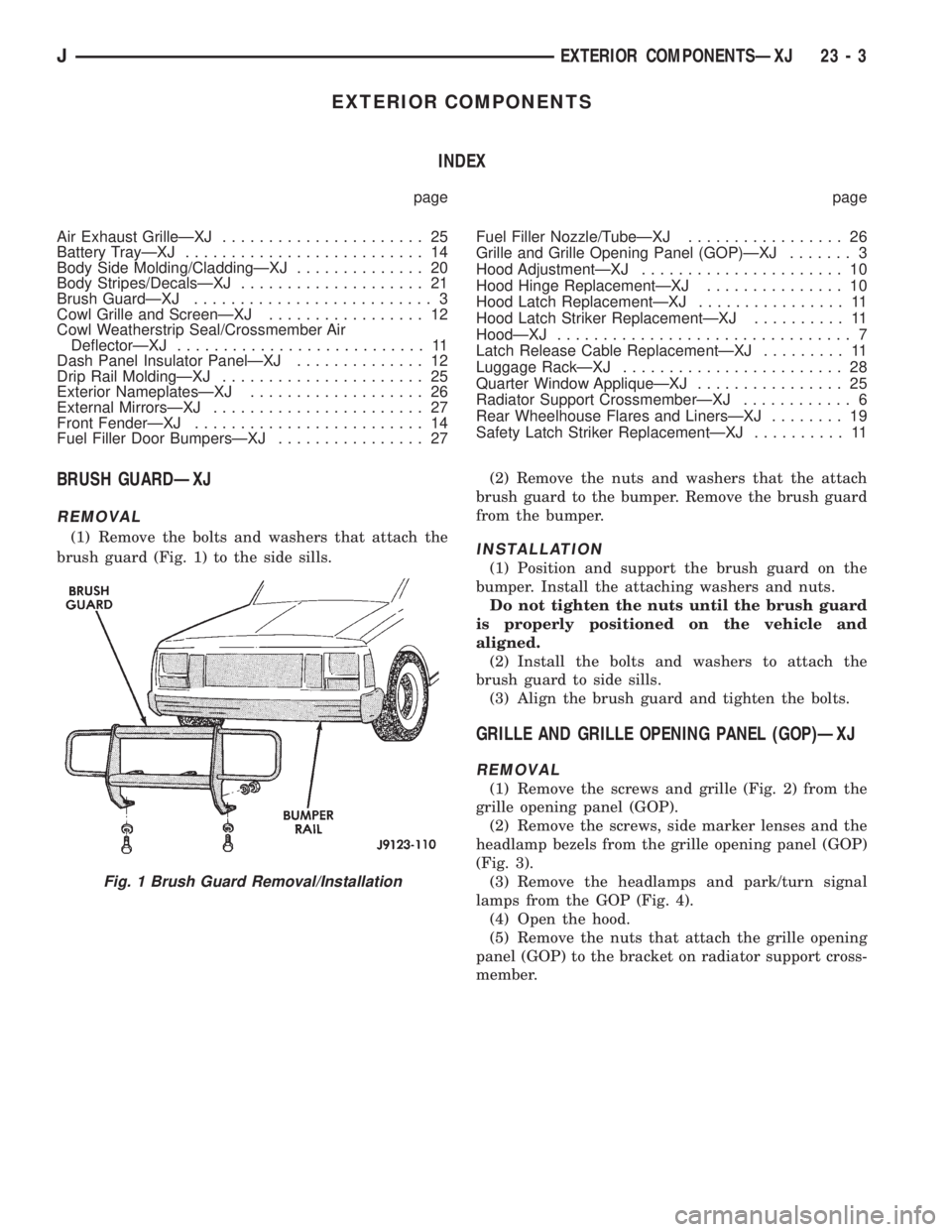
(1) Remove the bolts and washers that attach the
brush guard (Fig. 1) to the side sills.(2) Remove the nuts and washers that the attach
brush guard to the bumper. Remove the brush guard
from the bumper.INSTALLATION
(1) Position and support the brush guard on the
bumper. Install the attaching washers and nuts.
Do not tighten the nuts until the brush guard
is properly positioned on the vehicle and
aligned.
(2) Install the bolts and washers to attach the
brush guard to side sills.
(3) Align the brush guard and tighten the bolts.
GRILLE AND GRILLE OPENING PANEL (GOP)ÐXJ
REMOVAL
(1) Remove the screws and grille (Fig. 2) from the
grille opening panel (GOP).
(2) Remove the screws, side marker lenses and the
headlamp bezels from the grille opening panel (GOP)
(Fig. 3).
(3) Remove the headlamps and park/turn signal
lamps from the GOP (Fig. 4).
(4) Open the hood.
(5) Remove the nuts that attach the grille opening
panel (GOP) to the bracket on radiator support cross-
member.
Fig. 1 Brush Guard Removal/Installation
JEXTERIOR COMPONENTSÐXJ 23 - 3
Page 1945 of 2158
(3) Attach the hoses to the tubes with clamps.
Tighten the clamp screws to 4 Nzm (35 in-lbs) torque.
(4) Install the cap on nozzle.
(5) Install the fuel filler hose splash shield on the
quarter inner panel and frame rail.
(6) Install the fuel filler door on the quarter panel.
FUEL FILLER DOOR BUMPERSÐXJ
REPLACEMENT
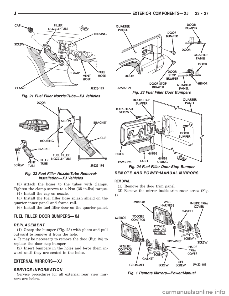
(1) Grasp the bumper (Fig. 23) with pliers and pull
outward to remove it from the hole.
²It may be necessary to remove the door (Fig. 24) to
replace the door-stop bumper.
(2) Insert bumpers in the holes and force them in-
ward until they are seated in the holes.
EXTERNAL MIRRORSÐXJ
SERVICE INFORMATION
Service procedures for all external rear view mir-
rors are below.
REMOTE AND POWER/MANUAL MIRRORS
REMOVAL
(1) Remove the door trim panel.
(2) Remove the mirror inside trim cover screw (Fig.
1).
Fig. 21 Fuel Filler Nozzle/TubeÐXJ Vehicles
Fig. 22 Fuel Filler Nozzle/Tube Removal/
InstallationÐXJ Vehicles
Fig. 23 Fuel Filler Door Bumpers
Fig. 24 Fuel Filler Door-Stop Bumper
Fig. 1 Remote MirrorsÐPower/Manual
JEXTERIOR COMPONENTSÐXJ 23 - 27
Page 1946 of 2158
(3) For power/manual mirrors, remove the inside
trim cover.
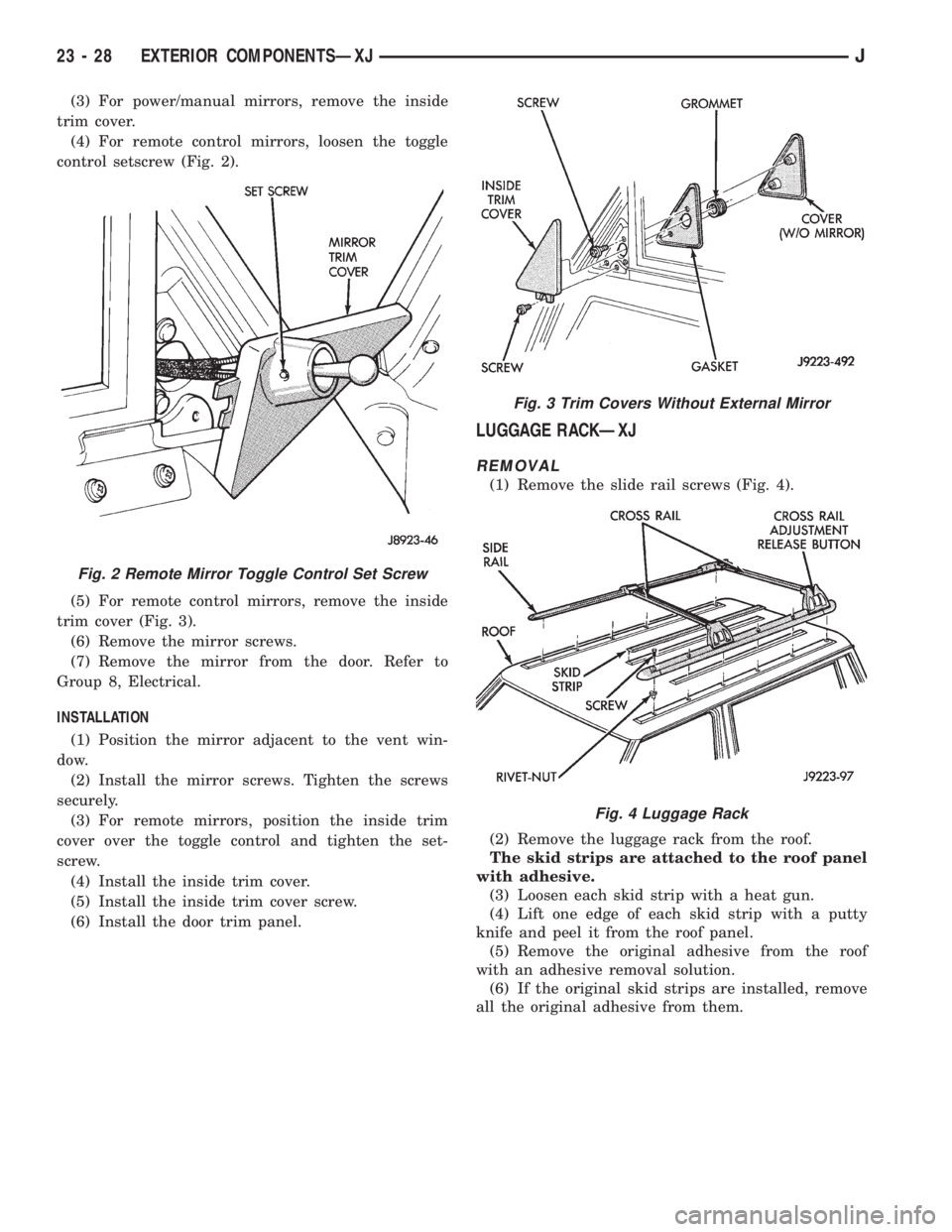
(4) For remote control mirrors, loosen the toggle
control setscrew (Fig. 2).
(5) For remote control mirrors, remove the inside
trim cover (Fig. 3).
(6) Remove the mirror screws.
(7) Remove the mirror from the door. Refer to
Group 8, Electrical.
INSTALLATION
(1) Position the mirror adjacent to the vent win-
dow.
(2) Install the mirror screws. Tighten the screws
securely.
(3) For remote mirrors, position the inside trim
cover over the toggle control and tighten the set-
screw.
(4) Install the inside trim cover.
(5) Install the inside trim cover screw.
(6) Install the door trim panel.
LUGGAGE RACKÐXJ
REMOVAL
(1) Remove the slide rail screws (Fig. 4).
(2) Remove the luggage rack from the roof.
The skid strips are attached to the roof panel
with adhesive.
(3) Loosen each skid strip with a heat gun.
(4) Lift one edge of each skid strip with a putty
knife and peel it from the roof panel.
(5) Remove the original adhesive from the roof
with an adhesive removal solution.
(6) If the original skid strips are installed, remove
all the original adhesive from them.
Fig. 2 Remote Mirror Toggle Control Set Screw
Fig. 3 Trim Covers Without External Mirror
Fig. 4 Luggage Rack
23 - 28 EXTERIOR COMPONENTSÐXJJ
Page 1984 of 2158
STATIONARY WINDOW GLASS
INDEX
page page
Interior Rearview MirrorÐXJ Removal and
Installation............................. 66
Interior Rearview Mirror Support Bracket
ReplacementÐXJ Preparation and Installation . . . 66
Description and Operation.......... ..........67
InstallationÐShort Method.......... ..........69
InstallationÐExtended Method........ ........71Rear Door Stationary Window Glass...... ......72
Rear Quarter Vent Window GlassÐXJ Removal
and Installation............. .............73
Rear Quarter Window Glass/Rear Quarter Plastic
InsertÐXJ Removal and Installation..... .....73
INTERIOR REARVIEW MIRRORÐXJ
MIRROR REMOVAL
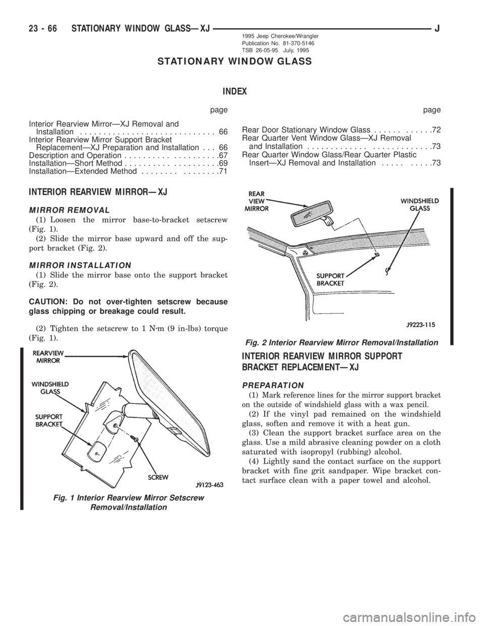
(1) Loosen the mirror base-to-bracket setscrew
(Fig. 1).
(2) Slide the mirror base upward and off the sup-
port bracket (Fig. 2).
MIRROR INSTALLATION
(1) Slide the mirror base onto the support bracket
(Fig. 2).
CAUTION: Do not over-tighten setscrew because
glass chipping or breakage could result.
(2) Tighten the setscrew to 1 Nzm (9 in-lbs) torque
(Fig. 1).
INTERIOR REARVIEW MIRROR SUPPORT
BRACKET REPLACEMENTÐXJ
PREPARATION
(1) Mark reference lines for the mirror support bracket
on the outside of windshield glass with a wax pencil.
(2) If the vinyl pad remained on the windshield
glass, soften and remove it with a heat gun.
(3) Clean the support bracket surface area on the
glass. Use a mild abrasive cleaning powder on a cloth
saturated with isopropyl (rubbing) alcohol.
(4) Lightly sand the contact surface on the support
bracket with fine grit sandpaper. Wipe bracket con-
tact surface clean with a paper towel and alcohol.
Fig. 1 Interior Rearview Mirror Setscrew
Removal/Installation
Fig. 2 Interior Rearview Mirror Removal/Installation
23 - 66 STATIONARY WINDOW GLASSÐXJJ1995 Jeep Cherokee/Wrangler
Publication No. 81-370-5146
TSB 26-05-95 July, 1995
Page 1985 of 2158
INSTALLATION
(1) Apply adhesive to the act surface on the sup-
port bracket according as follows:
²crush the vial in the plastic housing of the accel-
erator to saturate the felt applicator.
²remove the paper sleeve.
²apply a generous amount of accelerator to the con-
tact surface on the mirror support bracket.
²do not touch the support bracket contact surface
after the accelerator has been applied.
²
allow the accelerator to dry for at least five minutes.
and
(2) Apply accelerator to the support bracket con-
tact surface on the windshield glass. Allow the accel-
erator to dry for one minute.
(3) Install the mirror bracket on the windshield
glass as follows:
²apply one drop of adhesive at the center of support
bracket contact surface on windshield glass.
²immediately apply an even coat of adhesive to the
contact surface on the support bracket.
²align the support bracket with the position refer-
ence lines on the windshield glass, then
²press and hold the support bracket in-place for at
least one minute.
Ensure that the mirror support bracket is
correctly aligned because the adhesive will
cure rapidly.
(4) Allow the adhesive to cure for 8-10 minutes,
then remove any residue adhesive with an alcohol-
dampened cloth.
(5) Allow the adhesive to cure for an additional
8-10 minutes before installing the mirror base on the
support bracket.
DESCRIPTION AND OPERATION
SAFETY PRECAUTIONS
WARNING: DO NOT OPERATE THE VEHICLE
WITHIN 24 HOURS OF WINDSHIELD INSTALLATION.
IT TAKES AT LEAST 24 HOURS FOR THE URE-
THANE ADHESIVE TO CURE. IF IT IS NOT CURED,
THE WINDSHIELD MAY NOT PERFORM PROPERLY
IN AN ACCIDENT.
URETHANE ADHESIVES ARE APPLIED AS A SYS-
TEM. USE GLASS CLEANER, GLASS PREP SOL-
VENT, GLASS PRIMER, AND PINCHWELD (FENCE)
PRIMER PROVIDED BY THE ADHESIVE MANUFAC-
TURER. IF NOT, STRUCTURAL INTEGRITY COULD
BE COMPROMISED.
BE SURE TO REFER TO THE URETHANE MANU-
FACTURER'S DIRECTIONS FOR CURING TIME
SPECIFICATIONS, AND DO NOT USE ADHESIVE AF-
TER ITS EXPIRATION DATE.
VAPORS THAT ARE EMITTED FROM THE URE-
THANE ADHESIVE OR PRIMER COULD CAUSE
PERSONAL INJURY, USE THEM IN A WELL VENTI-
LATED AREA.
SKIN CONTACT WITH URETHANE ADHESIVE
SHOULD BE AVOIDED, OR PERSONAL INJURY MAY
RESULT.
ALWAYS WEAR EYE AND HAND PROTECTION
WHEN WORKING WITH GLASS.
CAUTION: Protect all painted or trimmed surfaces
from coming in contact with urethane or primers.
Be careful not to damage painted surfaces when
removing moldings or cutting urethane around
windshield.
It is difficult to salvage a windshield during the re-
moval operation. The windshield is part of the struc-
tural support for the roof. The urethane bonding
used to secure the windshield to the fence is difficult
to cut or clean from any surface. If the moldings are
set in urethane, it would also be unlikely they could
be salvaged. Before removing the windshield, check
the availability of the windshield and moldings from
the parts supplier.
JSTATIONARY WINDOW GLASSÐXJ 23 - 671995 Jeep Cherokee/Wrangler
Publication No. 81-370-5146
TSB 26-05-95 July, 1995